Page 111 of 364

44G6 – GENERAL INFORMATION/ SERVICING SPECIFICATIONS
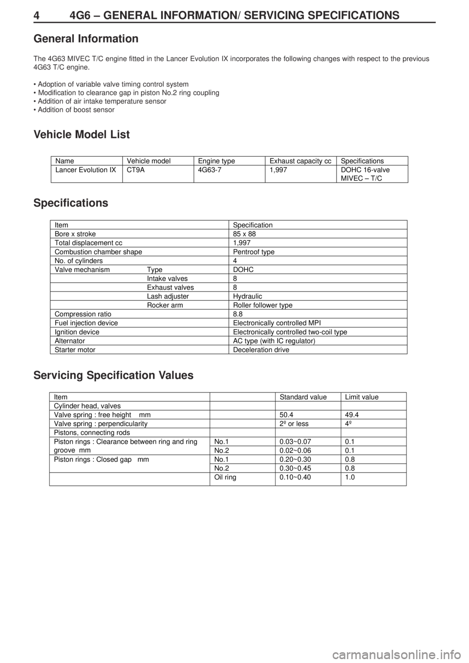
General Information
The 4G63 MIVEC T/C engine fitted in the Lancer Evolution IX incorporates the following changes with respect to the previous
4G63 T/C engine.
• Adoption of variable valve timing control system
• Modification to clearance gap in piston No.2 ring coupling
• Addition of air intake temperature sensor
• Addition of boost sensor
Vehicle Model List
Specifications
Servicing Specification Values
Name Vehicle model Engine type Exhaust capacity cc Specifications
Lancer Evolution IX CT9A 4G63-7 1,997 DOHC 16-valve
MIVEC – T/C
Item Specification
Bore x stroke 85 x 88
Total displacement cc 1,997
Combustion chamber shape Pentroof type
No. of cylinders 4
Valve mechanism Type DOHC
Intake valves 8
Exhaust valves 8
Lash adjuster Hydraulic
Rocker arm Roller follower type
Compression ratio 8.8
Fuel injection device Electronically controlled MPI
Ignition device Electronically controlled two-coil type
Alternator AC type (with IC regulator)
Starter motor Deceleration drive
g
Item Standard value Limit value
Cylinder head, valves
Valve spring : free height mm 50.4 49.4
Valve spring : perpendicularity 2º or less 4º
Pistons, connecting rods
No.1 0.03~0.07 0.1Piston rings : Clearance between ring and ring
groove mm
No.2 0.02~0.06 0.1
No.1 0.20~0.30 0.8Piston rings : Closed gap mm
No.2 0.30~0.45 0.8
Oil ring 0.10~0.40 1.0
Page 112 of 364

54G6 – TIGHTENING TORQUES
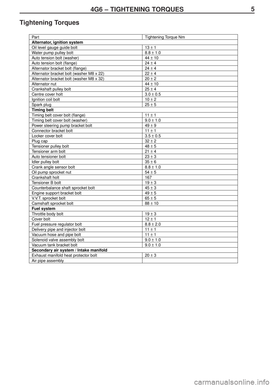
Tightening Torques
Par tTightening Torque Nm
Alternator, ignition system
Oil level gauge guide bolt13 ± 1
Water pump pulley bolt8.8 ± 1.0
Auto tension bolt (washer)44 ± 10
Auto tension bolt (flange)24 ± 4
Alternator bracket bolt (flange)24 ± 4
Alternator bracket bolt (washer M8 x 22)22 ± 4
Alternator bracket bolt (washer M8 x 32)20 ± 2
Alternator nut44 ± 10
Crankshaft pulley bolt25 ± 4
Centre cover holt3.0 ± 0.5
Ignition coil bolt10 ± 2
Spark plug25 ± 5
Timing belt
Timing belt cover bolt (flange)11 ± 1
Timing belt cover bolt (washer)9.0 ± 1.0
Power steering pump bracket bolt49 ± 9
Connector bracket bolt11 ± 1
Locker cover bolt3.5 ± 0.5
Plug cap32 ± 2
Tensioner pulley bolt48 ± 5
Tensioner arm bolt21 ± 4
Auto tensioner bolt23 ± 3
Idler pulley bolt35 ± 6
Crank angle sensor bolt8.8 ± 1.0
Oil pump sprocket nut54 ± 5
Crankshaft holt167
Tensioner B bolt19 ± 3
Counterbalance shaft sprocket bolt45 ± 3
Engine support bracket bolt49 ± 5
V.V.T. sprocket bolt65 ± 5
Camshaft sprocket bolt88 ± 10
Fuel system
Throttle body bolt19 ± 3
Cover bolt12 ± 1
Fuel pressure regulator bolt8.8 ± 2.0
Delivery pipe and injector bolt11 ± 1
Vacuum hose and pipe bolt11 ± 1
Solenoid valve assembly bolt9.0 ± 1.0
Vacuum tank bracket bolt9.0 ± 1.0
Secondary air system / Intake manifold
Exhaust manifold heat protector bolt20 ± 3
Air pipe assembly
Page 115 of 364
84G6 – ALTERNATOR / IGNITION SYSTEM
Alternator / Ignition System
Removal and Installation
Note :
The ignition coil boot must only be removed from the ignition coil when it is to be replaced.
If removed, always replace with a new part.
Removal sequence
1. Oil level gauge
2. O-ring
3. Oil level gauge guide
4. O-ring
5. Water pump pulley
6. Auto tensioner assembly
7. Alternator bracket8. Alternator
9. Crankshaft pulley
10. Centre cover
11. Spark plug cable
12. Ignition coil
13. Ignition coil boot
14. Spark plug
�A�*
Page 116 of 364

94G6 – ALTERNATOR, IGNITION SYSTEM
Removal Service Point
Removal of ignition coil boot
Note :
• If the ignition coil boot is not installed according to the
specifications, then this can lead to various problems, such
as malfunction of the ignition coil, damage to the ignition coil,
leaking of high voltage to external parts, infiltration of water
into the hole, etc.
• The spark plug coupling section of the ignition coil boot is
coated with a white powder. This coating helps to prevent the
boot from welding to the spark plug, and must not be touched
or wiped away.
1. Please check that a spring is fitted inside the new ignition coil
boot.
2. Press the new ignition coil boot firmly onto the ignition coil,
and turn the coupling section 2 or 3 times to seat it correctly
in position, ensuring that there are no gaps.
3. After installation, turn the boot until the air blow hole is
positioned as shown in the diagram.
Coupling
section
Air blow hole
White powder coating on
interior part. Do not touchAir blow hole
Upper face�A� �*
Page 142 of 364

GENERAL INFORMATION - HOW TO READ THE WIRING DIAGRAMS0-4
Reading Circuit Diagrams
These diagrams show the circuits for each system, from the fuse or fusible link to the earth. In principle, the power supply is
shown at the top and the earth at the bottom, to make it easier to understand the flow of current in the circuit.
The circuit diagrams show a state where none of the switches, etc. are operating.
Indicates power take-out
point.Indicates connector No. The same number is used in the layout
diagrams. Connector numbers shown inside a rounded box indicate
connector symbols that are listed together at the bottom of the page.
Connector numbers that are not shown inside a rounded box indicate
components that are incorporated into the harness.
Indicates that the terminal is
connected via a plate inside
the relay box.
Each circuit diagram is divided into
blocks shown on separate pages.
This number indicates the block.
Indicates the harness branch
point. This number matches the
branch numbers in the other
circuit diagrams.
Indicates the number of the circuit
to which the branch connects.
Indicates the power supply
within the control unit. If no
voltage is indicated, then it is
the battery voltage.
An "X" at the end of a connector
number shows that it is part of the
centralized relay. For more
information, refer to the section
covering the Centralized Junction.
Indicates that circuit diagram
continues at [A] in Block [2].
Indicates the connector symbol,
listed in the order of the connector
numbers in the circuit diagram.
Indicates the operating
conditions of the coolant
temperature switch, etc.Indicates shield
wire.An upward arrow indicates that
the current flows from bottom to
top in the diagram.
RegisterRelayMotor Relay boxFusible link
Fusible link
Diode
Sensor Switch
headlightsignition
Page 143 of 364

GENERAL INFORMATION - HOW TO READ THE WIRING DIAGRAMS0-5
Indicates input / output to
and from control unit
(direction of current flow).
Input Output Input/Output
Indicates a wiring connector inside a device,
which is not shown in the layout diagrams.
Example :
Indicates a connector
located inside a
device, numbered in
order starting from 1.
Indicates the number of the connector
shown in the layout diagram.
Indicates that these are the same
intermediate connector.
Indicates that the diagram
continues from section [A] in
block [1].
Indicates the terminal No.
If two or more connectors are
connected to the same device, a
broken line between parts indicates
that the same connector is used.
The two-way arrow shows that
current can flow downwards or
upwards, under the control of
the ECU.
Indicates a harness junction point
where the wire changes colour or
diameter.
Indicates an intersection
where the wires are not
connected.
Indicates an intersection
where the wires are
connected
Indicates the representative earth
point on the vehicle body for that
circuit. (This number matches that of
the earth point in the layout diagrams
and the diagrams of individual part
installation positions.)
Indicates a spare connector, if the
corresponding device is not
installed, due to the vehicle
specifications.Indicates the connector part number given in
the harness repair manual. A number in
( ) indicates the part number of the connector
that corresponds to a connector symbol.
Ignition
switch (IG1)
Solenoid
valve 1
Solenoid
valve
2
Solenoid
valve
ASSY
Sensor
MotorRegister
Page 144 of 364
GENERAL INFORMATION - HOW TO READ THE WIRING DIAGRAMS 0-6
Connector / Earth Markings
The circuits contain a large number of connectors and earths, and the following system has been adopted for depicting
connectors and earths in the circuit diagrams.
Ignition switchFusible link
Solenoid
valve
Inspection connector
MotorSensor
Page 156 of 364
LAYOUT DIAGRAMS - ENGINE / TRANSMISSION1-6
B-01 (1-black) Engine oil pressure switch
B-02 Alternator
B-03 (4-grey) Alternator
B-04 Starter
B-05 (1-black) Starter
B-06 (4-black) Throttle position sensorB-07 (2-black) Purge control solenoid valve
B-08 (7-black) Airflow sensor
B-12 (5-grey) Windscreen wiper motor
B-13X Engine speed detection connector
B-14X Starter relay
B-17X Ignition coil relay
ENGINE / TRANSMISSION
Connector Symbol
Control harnessGround cable
Battery
harness