Page 60 of 364

13A-20MPI – TROUBLESHOOTING
Measure at the inter-cooler water
spray relay connector C-220
•Undo the connector, and
measure on the harness side
•Voltage across earth 3 and 1
(ignition switch: ON)
OK:battery voltage
Measure at the engine ECU
connector C-50
•Undo the connector, and
measure on the harness side
•Voltage across earth 56
(ignition switch: ON)
OK:battery voltage
Check connector:C-31
Inspect the harness between the
inter-cooler water spray relay and
the inter-cooler water spray motor
•Check if the power supply wire
is cut, has short circuited, or is
damaged
Inspect the harness between the
inter-cooler water spray motor
and earth
•Check if the earth wire is cut, or
damaged
Check connectors C-209,
C-210, C-201 and C-208
Inspect the harness between the
inter-cooler water spray relay and
the ignition switch
•Check if the power supply wire
is damaged
Check connectors C-22 & C-50
Inspect the harness between the
inter-cooler water spray relay and
the engine ECU
•Check if the signal wire is
damaged
Check connector:A-34
Replace the engine ECU
Check the inter-cooler water
spray motor (Ref Section 15:
Intake/Exhaust)
Check connectorsC-209, C-210, C-201 and C-208
Inspect the harness between the inter-cooler water spray
relay and the ignition switch
•Check if the power supply wire is cut or has short circuited
Continued from the previous page
Check the ignition switch (Ref to Section 54)
Check connectorsC-22 and C-208
Inspect the harness between the inter-cooler water spray
relay and the engine ECU
•Check if the signal wire is cut or has short circuited
OK
OK
OK
OK
OK
OK
OK
OK
OK
OK
OK
OK
OK
OK
OK
NGNG
NG
NGNG
NG
NG
NG
NG
NG
NG
NG
NG
NG
Repair
Repair
Repair
Repair
Repair
Repair
Repair
Repair
Repair
Repair
Repair
Repair
Page 61 of 364

13A-21MPI – TROUBLESHOOTING
Check connector: B-32
Replace the No 2. waste gate solenoid
valve
Check connector:B-19X
Measure at the waste gate
solenoid valve connector B-32
•Undo the connector and
measure on the solenoid
valve side
•Resistance between 1-2
OK:29~35Ω(when at 20ºC)
Measure at the waste gate
solenoid valve connector B-32
•Undo the connector and
measure on the harness side
•Ignition switch: ON
•Voltage across earth at 63
OK:battery voltage
Measure at the engine ECU
connector C-50
•Measure the voltage at the
engine ECU terminal
•Ignition switch: ON
•Voltage across earth at 63
OK:battery voltage
Check connector:C-50
Inspect the harness between the
No.2 waste gate solenoid valve
and the engine ECU
•Check if the output wire is
damaged
Inspect the harness between the
No.2 waste gate solenoid valve
and the engine control relay
•Check if the power supply wire
is damaged
Replace the engine ECU
Inspect the harness between the No.2
waste gate solenoid valve and the
engine control relay, and repair if
necessary
•Check if the power supply wire is cut
or has short circuited
Check connector:C-50
Inspect the harness between the No.2
waste gate solenoid valve and the
engine ECU
•Check if the output wire is cut or has
short circuited
Replace the engine ECU
NG
OK
OK
OK
OK
OK
NG
NG
NG
NG
Repair
Repair
OK
OK
NG
NG
OK
Repair
NGRepair
Repair
No.2 waste gate solenoid valve systemProbable causes of the malfunction
The No.2 waste gate solenoid valve controls the supercharge pressure
introduced to the waste gate actuator in the turbocharger.•Malfunction of the No.2 waste gate
solenoid valve.
•Circuit break, short circuit or a faulty
connection in the No.2 waste gate
solenoid valve circuit.
•Malfunction of the engine ECU.
OKNGRepair
OKNGRepair
Inspection procedure 37
Page 62 of 364

13A-22MPI – TROUBLESHOOTING
Inspect the air temperature
sensor on its own (Ref: P13A-29)
Check connectorB-34
Measure at the air temperature
sensor connector B-34
•Undo the connector and
measure on the harness side
(1) Resistance across earth at 2
OK:Less than 2Ω
(2) Voltage across earth at 1
(Ignition switch: ON)
OK:4.9~5.1V
Go on to the next page
Replace the air temperature
sensor
Temporary malfunction (Ref
Section 00: Dealing with
temporary malfunctions)
Measure at the engine ECU
connector C-51
•Measure the voltage at the
engine ECU terminal
•Ignition switch: ON
•Voltage across earth at 96
OK:4.5~4.9V
Replace the engine ECU
Check that the problem has been
solved
Inspect the harness between the
air temperature sensor and the
engine ECU
•Check if the earth wire is cut
or damaged
Check connector:C-50
Inspect the harness between the
air temperature sensor and the
engine ECU and repair it if
necessary.
•Check if the output wire is cut
Check connector:C-51
Temporary malfunction (Ref
Section 00: Dealing with
temporary malfunctions)
Check connector:C-51
Check that the problem has been
solved
Replace the engine ECU
Inspect the harness between the
air temperature sensor and the
engine ECU and repair it if
necessary.
•Check if the output wire is cut
OKNG
(1) NG
(2) NG
NG
OK
OK
NG
NG
NG
OK
NG
OK
OK
OK
NG
NG
NG
NG
NG
OK
Repair
Repair
Repair
Repair
Repair
Air temperature sensor systemProbable causes of the malfunction
The air temperature sensor controls the temperature inside the inlet
manifold, and compensates for any burning of fuel.•Malfunction of the air temperature sensor.
•Circuit break, short circuit or a faulty connection in
the air temperature sensor circuit.
•Malfunction of the engine ECU.
Inspection procedure 38
OKNGRepair
Page 63 of 364
13A-23MPI – TROUBLESHOOTING
Continued from the previous page
Measure at the air temperature
sensor connector B-34
•Connect the test harness
(MB991658), to the connector
and measure at the pick-up
harness component.
•Ignition switch: ON
•Voltage across earth at 1
OK:
surrounding temperature -20ºC
3.8~4.4V
surrounding temperature 0ºC
3.2~3.8V
surrounding temperature 20ºC
2.3~2.9V
surrounding temperature 40ºC
1.5~2.1V
surrounding temperature 60ºC
0.8~1.4V
surrounding temperature 80ºC
0.4~1.0V
Check that the problem has been
solved
Replace the engine ECU
Inspect the harness between the
air temperature sensor and the
engine ECU and repair it if
necessary.
•Check if the earth wire is
damaged
Check connector: C-51
Temporary malfunction (Ref
Section 00: Dealing with
temporary malfunctions)
OK
OK
OK
NG
NG
OK
NGRepair
Page 80 of 364
INTAKE & EXHAUST – INLET MANIFOLD15-6
Removal procedure
1. Centre cover
2. Ignition coil connector
3. O
2sensor connector
4. Oil feeder control valve connector
5. Crank angle sensor connector
6. Injector connector
7. Air temperature sensor connector
8. Manifold absolute pressure sensor
connector
9. Purge control solenoid valve connector
10. Knock sensor connector
11.Fuel pressure solenoid valve connector12. Vacuum hose connection
13. Vacuum hose connection
14. Fuel return hose connection
15. Fuel high pressure hose connection
16. O-ring
17. Delivery pipe, injector and fuel pressure
regulator ASSY
18. Insulator
19. Insulator
20. Oil level gauge & guide ASSY
21. O-ring
22. Brake booster vacuum hose connection
23. Purge hose connection
� �
A� �
� �
A� �
�
�
A� �
Page 85 of 364

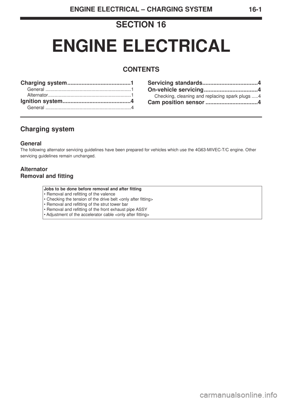
ENGINE ELECTRICAL – CHARGING SYSTEM
16-1
SECTION 16
ENGINE ELECTRICAL
CONTENTS
Charging system ........................................1
General .................................................................1
Alternator...............................................................1
Ignition system...........................................4
General .................................................................4
Servicing standards...................................4
On-vehicle servicing ..................................4
Checking, cleaning and replacing spark plugs .....4
Cam position sensor .................................4
Charging system
General
The following alternator servicing guidelines have been prepared for vehicles which use the 4G63-MIVEC-T/C engine. Other
servicing guidelines remain unchanged.
Alternator
Removal and fitting
Jobs to be done before removal and after fitting
• Removal and refitting of the valence
• Checking the tension of the drive belt
• Removal and refitting of the strut tower bar
• Removal and refitting of the front exhaust pipe ASSY
• Adjustment of the accelerator cable
Page 88 of 364
ENGINE ELECTRICAL – IGNITION SYSTEM16-4
Ignition system
General
The following servicing guidelines for spark plugs and the cam position sensor have been prepared for vehicles which use the
4G63-MIVEC-T/C engine. Other servicing guidelines remain unchanged.
Servicing standards
On-vehicle servicing
Checking cleaning and replacing spark plugs
The standard value and the upper limit for plug caps, has been changed in conjunction with the changes made to the spark
plugs. Other servicing guidelines remain unchanged.
Standard values and upper limits
Cam position sensor
Removal and fitting
Removal procedure
1. Cam position sensor connector
2. Cam position sensor
3. O-ringRemoval procedure
4. Cam position sensor connector
5. Cam position sensor
6. O-ring
ItemStandard ValueUpper Limit
Spark plug cap mm0.5~0.60.75
ManufacturerModelStandard Value mmUpper Limit mm
NGKILFR7H0.5~0.60.75
Page 108 of 364

Service Manual
4G6
FOREWORD
This manual contains information about the 4G6
DOHC engine. It only covers those points that are
different from the service manuals listed below.
Therefore, this manual should be used in conjunction
with the following manuals.
• 4G6 DOHC engine Service Manual (No. 1039G46)
• 4G6 DOHC engine Service Manual Supplement
(No.1039G63)
This manual is based on the engine specifications as of
March 2005. Please note that some engine details may
not match those given in this manual due to
subsequent changes in engine specifications. The units
shown in this manual are the standard international
SI units.
(However, conventional units are used for some figures
taken from existing documents)
If you have any opinions, requests or queries regarding
this manual, please write them down on the “Servicing
Comment Form” on the last page, and fax them to us.
March 2005
Mitsubishi Motor Corporation
This manual is printed on recycled paper.
CONTENTS
General Information . . . . . . . . . . . . . . . 4
Servicing Specification Values . . . . . . 4
Tightening torques . . . . . . . . . . . . . . . . 5
Sealants . . . . . . . . . . . . . . . . . . . . . . . . . 7
Alternator / Ignition system . . . . . . . . . 8
Timing belt . . . . . . . . . . . . . . . . . . . . . 10
Fuel system . . . . . . . . . . . . . . . . . . . . . 13
Secondary air system /
inlet manifold . . . . . . . . . . . . . . . . . . . 15
Exhaust manifold . . . . . . . . . . . . . . . . 16
Water pump / Water hose . . . . . . . . . 17
Rocker arm / Cam shaft . . . . . . . . . . . 18
Oil pump / Sump . . . . . . . . . . . . . . . . . 21
Pistons / Connecting rods . . . . . . . . . 22
Crank shaft / Cylinder block . . . . . . . 25
Turbocharger. . . . . . . . . . . . . . . . . . . . 27
DOHC
ENGINE