Page 1106 of 1500
DOOR
BODY42-39
DOOR GLASS AND REGULATOR
REMOVAL AND INSTALLATIONM1429001300326
Pre-removal Operation
Door Trim Assembly Removal (Refer to GROUP 52A
Door Trim P.52A-14).
Waterproof Film Removal (Refer to P.42-52).Post-installation Operation
Door Window Glass Adjustment (Refer to P.42-31).
Waterproof Film Installation (Refer to P.42-52).
Door Trim Assembly Installation (Refer to GROUP 52A,
Door Trim P.52A-14).
DOOR WINDOW REGULATOR
ASSEMBLY REMOVAL STEPS
DOOR BELTLINE MOLDING
(REFER TO P.42-52).1. DOOR WINDOW GLASS
2. WINDOW REGULATOR ASSEMBLYDOOR WINDOW REGULATOR
ASSEMBLY REMOVAL STEPS
Page 1108 of 1500
Page 1120 of 1500
DOOR
BODY42-53
REMOVAL
>>D<<1. DOOR WINDOW GLASS
RUNCHANNEL
WATERPROOF FILM AND DOOR
PANEL CORE REMOVAL STEPS
DOOR TRIM ASSEMBLY (REFER
TO GROUP 52A, DOOR TRIM
P.52A-14).
DOOR INSIDE HANDLE (REFER TO
P.42-46).
2. DOOR ARMREST BRACKET
>>A<<3. WATERPROOF FILM
4. DOOR PANEL CORE
DOOR OPENING INNER
WEATHERSTRIP REMOVAL
STEPS
FRONT SCUFF PLATE (REFER TO
GROUP 52A, TRIMS P.52A-11).
>>C<<5. DOOR OPENING INNER
WEATHERSTRIP (BODY SIDE)DOOR OPENING OUTER
WEATHERSTRIP REMOVAL
STEPS
DOOR CHECK MOUNTING BOLT
(BODY SIDE) (REFER TO P.42-37).
>>B<<6. DOOR OPENING OUTER
WEATHERSTRIP
DOOR BELTLINE MOLDING
REMOVAL STEPS
DOOR TRIM ASSEMBLY (REFER
TO GROUP 52A, DOOR TRIM
P.52A-14).
REMOTE CONTROLLED MIRROR
ASSEMBLY (REFER TO GROUP 51,
DOOR MIRROR P.51-28).
7. DOOR BELTLINE MOLDING
Page 1123 of 1500
DOOR
BODY42-56
DOUBLE-SIDED TAPE POSITION
WATERPROOF FILM REMOVAL
STEPS
DOOR TRIM ASSEMBLY (REFER
TO GROUP 52A, DOOR TRIM
P.52A-14).
DOOR INSIDE HANDLE (REFER TO
P.42-46).
>>A<<4. WATERPROOF FILM
DOOR OPENING INNER
WEATHERSTRIP REMOVAL
STEPS
REAR SCUFF PLATE (REFER TO
GROUP 52A, TRIMS P.52A-11).
>>C<<5. DOOR OPENING INNER
WEATHERSTRIP (BODY SIDE)DOOR OPENING OUTER
WEATHERSTRIP REMOVAL
STEPS
DOOR CHECK MOUNTING BOLT
(BODY SIDE) (REFER TO P.42-37).
>>B<<6. DOOR OPENING OUTER
WEATHERSTRIP
DOOR BELTLINE MOLDING
REMOVAL STEPS
DOOR TRIM ASSEMBLY (REFER
TO GROUP 52A, DOOR TRIM
P.52A-14).
7. DOOR BELTLINE MOLDING
Page 1223 of 1500

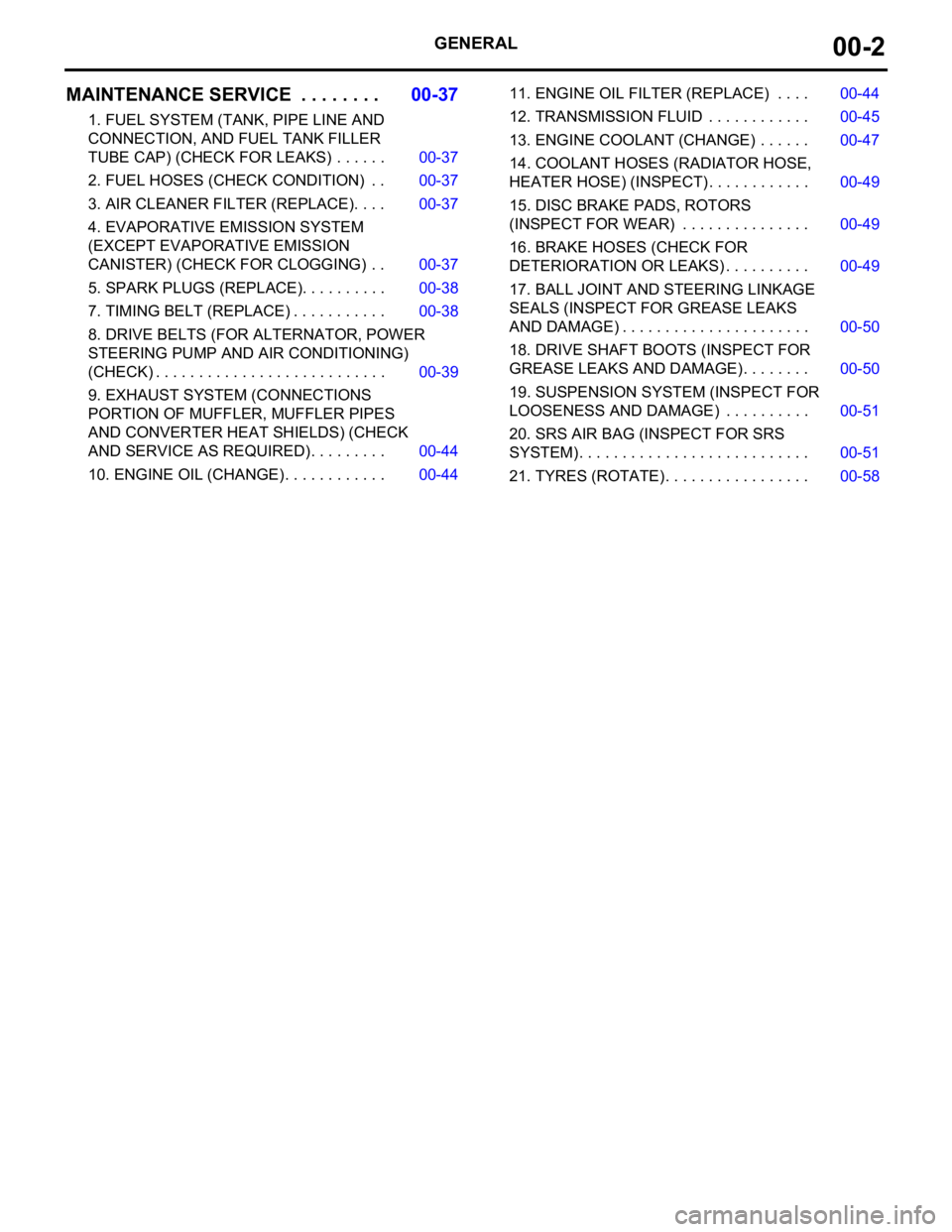
GENERAL00-2
MAINTENANCE SERVICE . . . . . . . .00-37
1. FUEL SYSTEM (TANK, PIPE LINE AND
CONNECTION, AND FUEL TANK FILLER
TUBE CAP) (CHECK FOR LEAKS) . . . . . . 00-37
2. FUEL HOSES (CHECK CONDITION) . . 00-37
3. AIR CLEANER FILTER (REPLACE). . . . 00-37
4. EVAPORATIVE EMISSION SYSTEM
(EXCEPT EVAPORATIVE EMISSION
CANISTER) (CHECK FOR CLOGGING) . . 00-37
5. SPARK PLUGS (REPLACE). . . . . . . . . . 00-38
7. TIMING BELT (REPLACE) . . . . . . . . . . . 00-38
8. DRIVE BELTS (FOR ALTERNATOR, POWER
STEERING PUMP AND AIR CONDITIONING)
(CHECK) . . . . . . . . . . . . . . . . . . . . . . . . . . . 00-39
9. EXHAUST SYSTEM (CONNECTIONS
PORTION OF MUFFLER, MUFFLER PIPES
AND CONVERTER HEAT SHIELDS) (CHECK
AND SERVICE AS REQUIRED) . . . . . . . . . 00-44
10. ENGINE OIL (CHANGE) . . . . . . . . . . . . 00-4411. ENGINE OIL FILTER (REPLACE) . . . . 00-44
12. TRANSMISSION FLUID . . . . . . . . . . . . 00-45
13. ENGINE COOLANT (CHANGE) . . . . . . 00-47
14. COOLANT HOSES (RADIATOR HOSE,
HEATER HOSE) (INSPECT). . . . . . . . . . . . 00-49
15. DISC BRAKE PADS, ROTORS
(INSPECT FOR WEAR) . . . . . . . . . . . . . . . 00-49
16. BRAKE HOSES (CHECK FOR
DETERIORATION OR LEAKS) . . . . . . . . . . 00-49
17. BALL JOINT AND STEERING LINKAGE
SEALS (INSPECT FOR GREASE LEAKS
AND DAMAGE) . . . . . . . . . . . . . . . . . . . . . . 00-50
18. DRIVE SHAFT BOOTS (INSPECT FOR
GREASE LEAKS AND DAMAGE) . . . . . . . . 00-50
19. SUSPENSION SYSTEM (INSPECT FOR
LOOSENESS AND DAMAGE) . . . . . . . . . . 00-51
20. SRS AIR BAG (INSPECT FOR SRS
SYSTEM). . . . . . . . . . . . . . . . . . . . . . . . . . . 00-51
21. TYRES (ROTATE). . . . . . . . . . . . . . . . . 00-58
Page 1243 of 1500

PRECAUTIONS BEFORE SERVICE
GENERAL00-22
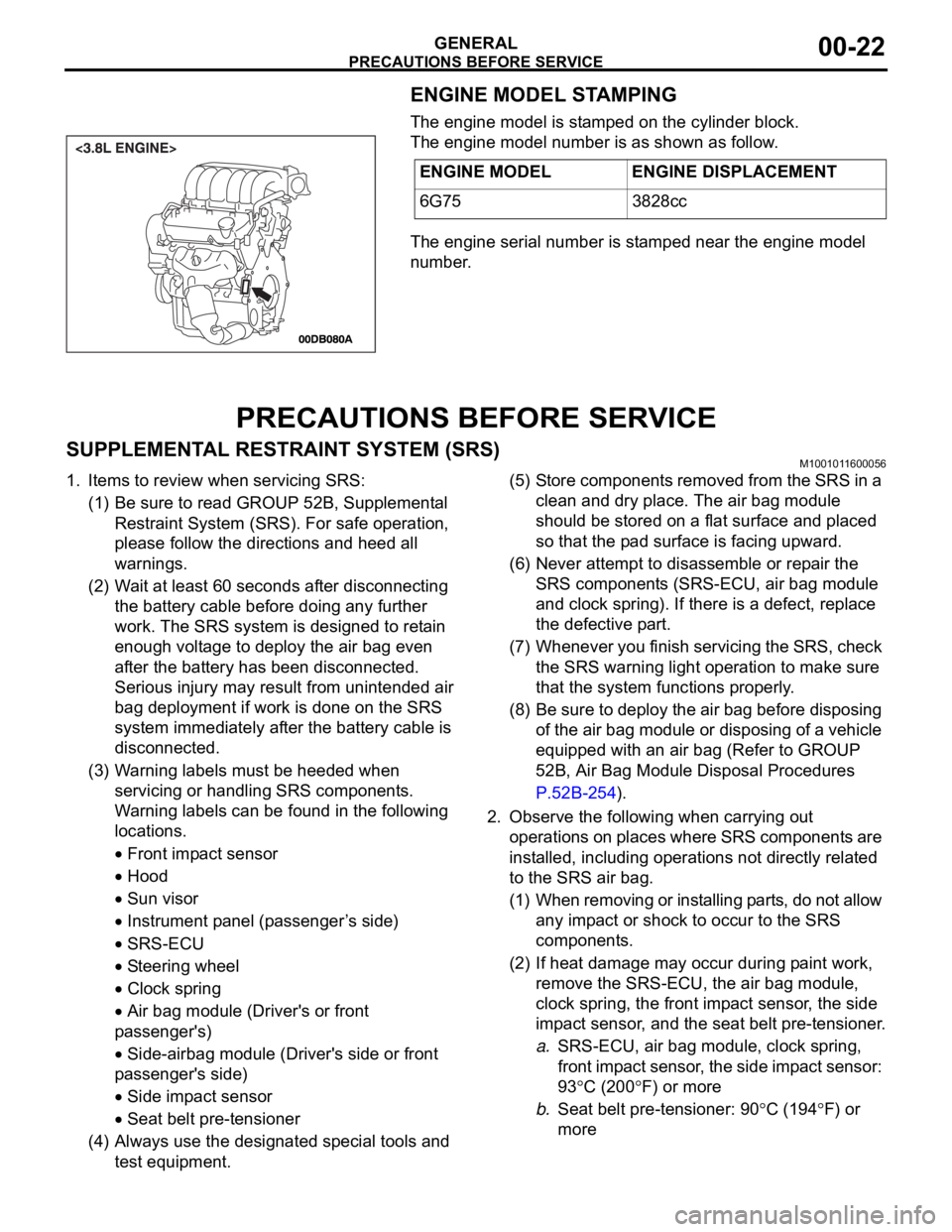
ENGINE MODEL STAMPING
The engine model is stamped on the cylinder block.
The engine model number is as shown as follow.
The engine serial number is stamped near the engine model
number.
PRECAUTIONS BEFORE SERVICE
SUPPLEMENTAL RESTRAINT SYSTEM (SRS)M1001011600056
1. Items to review when servicing SRS:
(1) Be sure to read GROUP 52B, Supplemental
Restraint System (SRS). For safe operation,
please follow the directions and heed all
warnings.
(2) Wait at least 60 seconds after disconnecting
the battery cable before doing any further
work. The SRS system is designed to retain
enough voltage to deploy the air bag even
after the battery has been disconnected.
Serious injury may result from unintended air
bag deployment if work is done on the SRS
system immediately after the battery cable is
disconnected.
(3) Warning labels must be heeded when
servicing or handling SRS components.
Warning labels can be found in the following
locations.
Front impact sensor
Hood
Sun visor
Instrument panel (passenger ’s side)
SRS-ECU
Steering wheel
Clock spring
Air bag module (Driver's or front
passenger's)
Side-airbag module (Driver's side or front
passenger's side)
Side impact sensor
Seat belt pre-tensioner
(4) Always use the designated special tools and
test equipment.(5) Store components removed from the SRS in a
clean and dry place. The air bag module
should be stored on a flat surface and placed
so that the pad surface is facing upward.
(6) Never attempt to disassemble or repair the
SRS components (SRS-ECU, air bag module
and clock spring). If there is a defect, replace
the defective part.
(7) Whenever you finish servicing the SRS, check
the SRS warning light operation to make sure
that the system functions properly.
(8) Be sure to deploy the air bag before disposing
of the air bag module or disposing of a vehicle
equipped with an air bag (Refer to GROUP
52B, Air Bag Module Disposal Procedures
P.52B-254).
2. Observe the following when carrying out
operations on places where SRS components are
installed, including operations not directly related
to the SRS air bag.
(1) When removing or installing parts, do not allow
any impact or shock to occur to the SRS
components.
(2) If heat damage may occur during paint work,
remove the SRS-ECU, the air bag module,
clock spring, the front impact sensor, the side
impact sensor, and the seat belt pre-tensioner.
a.SRS-ECU, air bag module, clock spring,
front impact sensor, the side impact sensor:
93
C (200F) or more
b.Seat belt pre-tensioner: 90
C (194F) or
more ENGINE MODEL ENGINE DISPLACEMENT
6G75 3828cc
Page 1259 of 1500
MAINTENANCE SERVICE
GENERAL00-38
5. SPARK PLUGS (REPLACE)M1001002000346
Iridium plugs are used. Use care not to damage the iridium
tips of the plugs. Do not adjust the spark plug gap.
1. Spark plugs must spark properly to assure proper engine
performance and reduce exhaust emission level. Therefore,
they should be replaced periodically with new ones( Refer to
Maintainence Schedule).
Spark plug type
2. The new plugs should be checked for the proper gap.
Spark plug gap: 1.0
1.1 mm
3. Install the spark plugs and tighten to 25
5 Nm (18 4
ft-lb).
6. TIMING BELT (REPLACE)M1001002300273
Replace the belt with a new one according to the vehicle main-
tenance schedule to assure proper engine performance.
<3.8L ENGINE>
For removal and installation procedures, refer to GROUP 11C,
Engine Mechanical <3.8L Engine>
Timing Belt Removal
and Installation P.11A-46.MAKER 3.8L ENGINE
BOSCH FR8DI30
Page 1260 of 1500
MAINTENANCE SERVICE
GENERAL00-39
7. DRIVE BELTS (FOR ALTERNATOR, POWER
STEERING PUMP AND AIR CONDITIONING)
(CHECK)
M1001008700031
ALTERNATOR DRIVE BELT TENSION CHECK
<3.8L ENGINE>
.
WHEN USING DIAGNOSTIC TOOL (MUT-III)
Required Special Tools:
MB991668: Belt Tension Meter Set
Diagnostic Tool (MUT-III)
MB991824: Vehicle Communication Interface (V.C.I.)
MB991910: MUT-III Main Harness A (BLUE)
To prevent damage to DIAGNOSTIC TOOL (MUT-III), always
turn the ignition switch to the "LOCK" (OFF) position
before connecting or disconnecting.
1. Connect Belt Tension Meter Set (MB991668) to V.C.I
(MB991824).
2. Connect MUT-III Main Harness A (BLUE) (MB991910) to
V.C.I (MB991824).
3. Connect MUT-III Main Harness A (BLUE) (MB991910) to the
data link connector.
4. Turn the ignition switch to the "ON" position and select "Belt
Tension" from the menu V.C.I (MB991824) screen.