Page 1386 of 1500

AUTO-CRUISE CONTROL
ENGINE AND EMISSION CONTROL17-55
INSPECTION PROCEDURE 3: When the Auto-cruise Control "CANCEL" Switch is Set to ON,
Auto-cruise Control System is not Cancelled.
.
COMMENT
The cause is probably an open-circuit in the output in
the circuit inside the "CANCEL" switch.
.
TROUBLESHOOTING HINTS (THE MOST
LIKELY CAUSES FOR THIS CASE:)
Malfunction of the auto-cruise control switch.
Circuit drawings
Refer to circuit diagrams GROUP-90
Refer to configuration diagrams GROUP-80
Refer to component locations GROUP-70
DIAGNOSIS
Replace the auto-cruise control switch. (Refer to P.17-75,
Auto-cruise Control).
INSPECTION PROCEDURE 4: When the Clutch Pedal is Depressed, Auto-cruise Control System is not
Cancelled.
.
COMMENT
The clutch switch circuit is suspected.
.
TROUBLESHOOTING HINTS (THE MOST
LIKELY CAUSES FOR THIS CASE:)
Malfunction of the clutch switch.
Damaged harness or connector.
Malfunction of the Engine ECU.
Circuit drawings
Refer to circuit diagrams GROUP-90
Refer to configuration diagrams GROUP-80
Refer to component locations GROUP-70
DIAGNOSIS
Refer to P.17-15, Diagnostic Trouble Code Procedures DTC
0830: Clutch Switch System.
Page 1396 of 1500

AUTO-CRUISE CONTROL
ENGINE AND EMISSION CONTROL17-65
DATA LIST REFERENCE TABLE - Auto Cruise ControlM1172002400471
When shifting the selector lever to "D" range, apply the brakes so that the vehicle does not move
forward.
Driving tests always need two persons: one driver and one observer.
NOTE: *:After the inspection is completed, disconnect the throttle position sensor connector, and then delete
the diagnostic trouble code using use of Diagnostic Tool MB991958. (Refer to P.17-11).
MUT-III
Diagnostic
To o l
DISPLAYITEM
NO.INSPECTION ITEM INSPECTION REQUIREMENT NORMAL
CONDITION
APS
SNS(MAIN)11 A c c e l e r a t o r p e d a l
position sensor (main)Ignition
switch:
"ON"Accelerator pedal: Released
435
1,035 mV
Accelerator pedal: Gradually
depressedIncreases in
response to the
pedal depression
stroke
Accelerator pedal: Fully
depressed4,000 mV or more
BRAKE SW 89 Stoplamp switch Brake pedal: Depressed ON
Brake pedal: Released OFF
CANCEL
CODE57 Cancel code Ignition switch: "ON" The cancel code,
which set when the
auto-cruise control
system was
cancelled at the
last time, is set
again.
CANCEL
SWITCH75 Auto-cruise
control
switchCANCEL "CANCEL" switch: ON ON
"CANCEL" switch: OFF OFF
CLUTCH SW 78 Transmission inhibitor
switchTransmission inhibitor switch: "P" or
"N"ON
Transmission inhibitor switch: Other
than aboveOFF
CRUISE 81 Auto-cruise control
system operationAuto-cruise control system: active ON
Auto-cruise control system: Inactive OFF
MAIN SW 86 Auto-cruise
control
switchCRUISE
(MAIN)"CRUISE" (MAIN) switch: "ON" ON
"CRUISE" (MAIN) switch: "OFF" OFF
RESUME
SWITCH91 Auto-cruise
control
switchACC/RES "ACC/RES" switch: ON ON
"ACC/RES" switch: OFF OFF
SET SWITCH 92 Auto-cruise
control
switchCOAST/S
ET"COAST/SET" switch: ON ON
"COAST/SET" switch: OFF OFF
STOPLIGHT
SW74 Stoplamp switch Brake pedal: Depressed ON
Brake pedal: Released OFF
Page 1462 of 1500
GENERAL DESCRIPTION
AUTOMATIC TRANSMISSION23A-3
GENERAL DESCRIPTIONM1231000100366
ITEM SPECIFICATION
Transmission modelF5A5A-4-C5Z
Engine model 6G75-S4-MP
Torque converter Type 3-element, 1-stage, 2-phase type
Lock-up Provided
Stall torque ratio 1.71
Transmission type5 forward speeds, 1 reverse speed, fully automatic
Transmission gear
ratio1st 3.789
2nd 2.162
3rd 1.421
4th 1.000
5th 0.686
Reverse 3.117
Final reduction ratio (Differential gear ratio) 3.325
Clutch Multi-disc type 4 sets
Brake Multi-disc type 2 sets, band type 1 set
Manual control system P-R-N-D (4 position) + Sport mode (up, down)
Shift pattern control Electronic control
Hydraulic control during shifting Electronic control (Each clutch hydraulically independently
controlled)
Torque converter clutch control Electronic control
Transmission fluid Specified lubricants MITSUBISHI ELC4-SP III
Quantity (litres) 8.4
Page 1463 of 1500

GENERAL DESCRIPTION
AUTOMATIC TRANSMISSION23A-4
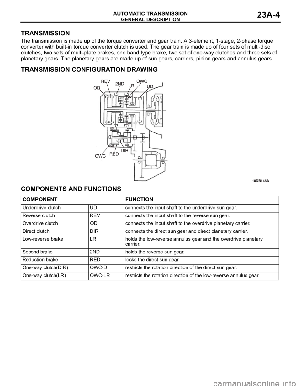
TRANSMISSION
The transmission is made up of the torque converter and gear train. A 3-element, 1-stage, 2-phase torque
converter with built-in torque converter clutch is used. The gear train is made up of four sets of multi-disc
clutches, two sets of multi-plate brakes, one band type brake, two set of one-way clutches and three sets of
planetary gears. The planetary gears are made up of sun gears, carriers, pinion gears and annulus gears.
.
TRANSMISSION CONFIGURATION DRAWING
.
COMPONENTS AND FUNCTIONS
COMPONENT FUNCTION
Underdrive clutch UD connects the input shaft to the underdrive sun gear.
Reverse clutch REV connects the input shaft to the reverse sun gear.
Overdrive clutch OD connects the input shaft to the overdrive planetary carrier.
Direct clutch DIR connects the direct sun gear and direct planetary carrier.
Low-reverse brake LR holds the low-reverse annulus gear and the overdrive planetary
carrier.
Second brake 2ND holds the reverse sun gear.
Reduction brake RED locks the direct sun gear.
One-way clutch(DIR) OWC-D restricts the rotation direction of the direct sun gear.
One-way clutch(LR) OWC-LR restricts the rotation direction of the low-reverse annulus gear.
Page 1464 of 1500
GENERAL DESCRIPTION
AUTOMATIC TRANSMISSION23A-5
FUNCTION ELEMENT TABLE
: Function element : Not applicable
NOTE: * operates only when the vehicle is stationary [at approximately 10 km/h (6.2 mph) or less].
OPERATING
ELEMENTSTART PARKING
MECHANI
SMUNDER
DRIVE
CLUTCH
(UD)REVERSE
CLUTCH
(REV)OVER-
DRIVE
CLUTCH
(OD)DIRECT
CLUTCH
(DIR)LOW-
REVERSE
BRAKE
(LR)SECOND
BRAKE
(2ND)REDUCTI-
ON
BRAKE
(RB) TRANSMISSION
RANGE
POK
R
NOK
Sport
mode1st*
2nd
3rd
4th
5th
Page 1465 of 1500
GENERAL DESCRIPTION
AUTOMATIC TRANSMISSION23A-6
SECTIONAL VIEW
1. OVERDRIVE CLUTCH
2. REVERSE CLUTCH
3. OVERDRIVE PLANETARY CARRIER
4. OUTPUT PLANETARY CARRIER
5. SECOND BRAKE
6. LOW-REVERSE BRAKE
7. ONE-WAY CLUTCH
8. TRANSFER DRIVE GEAR
9. TRANSMISSION CASE
10. UNDERDRIVE CLUTCH
11. OIL PUMP
12. TORQUE CONVERTER HOUSING13. TORQUE CONVERTER CLUTCH
14. TORQUE CONVERTER
15. INPUT SHAFT
16. DIFFERENTIAL
17. REAR COVER
18. OUTPUT SHAFT
19. DIRECT CLUTCH
20. REDUCTION BRAKE BAND
21. DIRECT PLANETARY CARRIER
22. TRANSFER DRIVEN GEAR
23. OUTPUT GEAR
24. DIFFERENTIAL DRIVE GEAR
Page 1470 of 1500
GENERAL DESCRIPTION
AUTOMATIC TRANSMISSION23A-11
TORQUE CONVERTER CLUTCH CONTROL.
5TH GEAR RANGE
.
4TH GEAR RANGE
Page 1477 of 1500

AUTOMATIC TRANSMISSION DIAGNOSIS
AUTOMATIC TRANSMISSION23A-18
FAIL-SAFE/BACKUP FUNCTIONM1231008300234
When a malfunction of a main sensor or actuator is
detected by the A/T-ECU, the transmission is con-
trolled by pre-set control logic to maintain safe condi-
tions for driving.The following table shows how the fail-safe/backup
function affects vehicle driveability and operation.
MALFUNCTIONING ITEM JUDGEMENT
CONDITIONCONTROL DEFAULT DURING MALFUNCTION
Input shaft speed sensor If no output pulse
from the input shaft
speed sensor is
detected for one
second or more
when the vehicle
speed is 30 km/h (19
mph) or greater.The diagnostic trouble code is recorded when the
malfunction occurs during 4 monitoring periods in
one drive cycle. When the judgment condition is
met, the transmission holds 3rd gear or 2nd gear,
depending on speed, as a fail-safe.
Output shaft speed sensor The output signal
from the output shaft
speed sensor is not
present for one
second or more
while the vehicle is
driven.The diagnostic trouble code is recorded when the
malfunction occurs during 4 monitoring periods in
one drive cycle. When the judgment condition is
met, the transmission holds 3rd gear or 2nd gear,
depending on speed, as a fail-safe.
Low-reverse solenoid valve Solenoid valve
resistance is below
2.7 ohms for 0.32
seconds.The diagnostic trouble code is recorded when the
malfunction occurs during 5 monitoring periods in
one drive cycle. When the judgment condition is
met, the A/T control relay is turned off. The
transmission will only operate in 3rd and reverse
gears until the system is repaired. Underdrive solenoid valve
Second solenoid valve
Overdrive solenoid valve
Reduction (RED) solenoid valve
Damper control clutch (DCC)
solenoid valve
Incomplete shifting 1st The gear ratio value
from the output shaft
speed sensor is not
the same as the
output from the input
shaft speed sensor
for one second after
shifting has been
completed.The diagnostic trouble code is recorded when the
malfunction occurs during 5 monitoring periods in
one drive cycle. When the judgment condition is
met, the A/T control relay is turned off. The
transmission will only operate in 3rd and reverse
gears until the system is repaired. 2nd
3rd
4th
5th
Reverse
A/T control relay A/T control relay
voltage is less than
seven volts for 0.1
second after the
ignition switch is
turned "ON."The A/T control relay is switched off. The
transmission will only operate in 3rd and reverse
gears until the system is repaired.
Malfunction in the A/T-ECU Malfunction has
occurred in the
A/T-ECU.The A/T control relay is switched off. The
transmission will only operate in 3rd and reverse
gears until the system is repaired.