Page 879 of 1500

SPECIFICATIONS
HEATER, AIR CONDITIONING AND VENTILATION55-178
SPECIFICATIONS
FASTENER TIGHTENING SPECIFICATIONSM1552012100273
GENERAL SPECIFICATIONSM1552000200262
SERVICE SPECIFICATIONSM1552000300333
LUBRICANTSM1552000400329
ITEM SPECIFICATION
Liquid pipe mounting nut (heater unit side) 4.9
0.9 Nm (43 8 in-lb)
Liquid pipe mounting bolt (condenser side) 4.9
0.9 Nm (44 8 in-lb)
Suction flexible hose mounting nut (compressor side) 25
4 Nm (18 3 ft-lb)
Suction pipe mounting nut (heater unit side) 12
2 Nm (107 17 in-lb)
Suction pipe to suction hose union nut 32
2 Nm
Discharge flexible hose mounting bolt (compressor side) 25
4 Nm (18 3 ft-lb)
Discharge flexible hose mounting nut (condenser side) 12
2 Nm (107 17 in-lb)
ITEM MANUAL AIR CONDITIONING
Heater control Dial type
Air conditioning switch Push-button type
Compressor Type 10S17 (Swashplate type)
Displacement (cm
3)188
Refrigerant Type R134a (HFC-134a)
Amount (grams) 435
475
ITEM STANDARD VALUE
Idle speed r/min 680
50
Idle-up speed r/min 680
50
Air mix damper potentiometer resistance k
1.7 5.0
Air outlet changeover damper potentiometer resistance k
0.8 4.8
Air gap (air conditioning compressor clutch) mm (in) 0.3
0.5 (0.012 0.020)
ITEM SPECIFIED LUBRICANT QUANTITY(ml)
Each connection of refrigerant line ND Oil 8 As required
Compressor refrigerant unit lubricant (ml) ND Oil 8 140
Page 885 of 1500
RELAY
COMPONENT LOCATIONS70-6
RELAYM1701000400381
NAME SYMBOL NAME SYMBOL
A/C compressor clutch relay A Fuel pump relay (2) C
A/T control relay A Horn relay A
Accessory socket relay C Rear window defogger relay C
Blower relay C MPI relay A
Fan control relay A Power window relay C
Fog Lamp relay A Rear window defogger relay C
Fuel pump relay (1) C
Page 997 of 1500

STARTING SYSTEM
ENGINE ELECTRICAL16-20
STARTING SYSTEM
GENERAL DESCRIPTIONM1162000100235
If the ignition switch is turned to the "START" posi-
tion, current flows in the coil provided inside mag-
netic switch, attracting the plunger. When the plunger
is attracted, the lever connected to the plunger is
actuated to engage the starter clutch.
On the other hand, attracting the plunger will turn on
the magnetic switch, allowing the "B" terminal and
"M" terminal to conduct. Thus, current flows to
engage the starter motor.When the ignition switch is returned to the "ON" posi-
tion after starting the engine, the starter clutch is dis-
engaged from the ring gear.
An overrunning clutch is provided between the pinion
and the armature shaft, to prevent damage to the
starter.
OPERATION
When the ignition switch is switched to the "ST" posi-
tion while the selector lever is at the "P" or "N" range,
the contact (magnetic switch) of the starter is
switched ON and the starter motor is activated.
Page 1003 of 1500
Page 1004 of 1500
Page 1006 of 1500

STARTING SYSTEM
ENGINE ELECTRICAL16-29
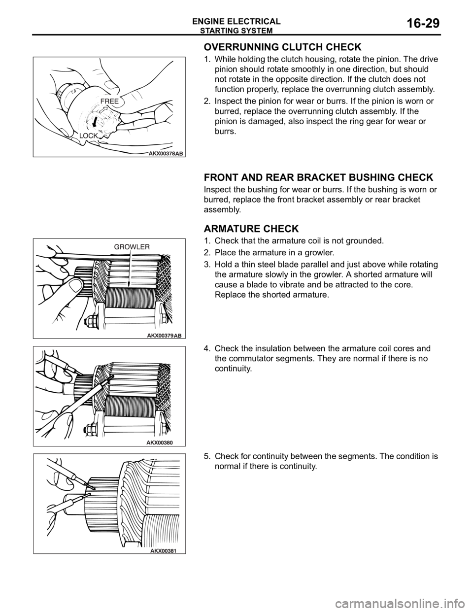
OVERRUNNING CLUTCH CHECK
1. While holding the clutch housing, rotate the pinion. The drive
pinion should rotate smoothly in one direction, but should
not rotate in the opposite direction. If the clutch does not
function properly, replace the overrunning clutch assembly.
2. Inspect the pinion for wear or burrs. If the pinion is worn or
burred, replace the overrunning clutch assembly. If the
pinion is damaged, also inspect the ring gear for wear or
burrs.
.
FRONT AND REAR BRACKET BUSHING CHECK
Inspect the bushing for wear or burrs. If the bushing is worn or
burred, replace the front bracket assembly or rear bracket
assembly.
.
ARMATURE CHECK
1. Check that the armature coil is not grounded.
2. Place the armature in a growler.
3. Hold a thin steel blade parallel and just above while rotating
the armature slowly in the growler. A shorted armature will
cause a blade to vibrate and be attracted to the core.
Replace the shorted armature.
4. Check the insulation between the armature coil cores and
the commutator segments. They are normal if there is no
continuity.
5. Check for continuity between the segments. The condition is
normal if there is continuity.
Page 1066 of 1500
21-1
GROUP 21
CLUTCH
CONTENTS
CLUTCH . . . . . . . . . . . . . . . . . . . . . . . . . . . . . . . . . . . . . . . . . . .21A
CLUTCH OVERHAUL . . . . . . . . . . . . . . . . . . . . . . . . . . . . . . . . .21B
Page 1156 of 1500
21A-1
GROUP 21A
CLUTCH
CONTENTS
GENERAL INFORMATION . . . . . . . .21A-2
SERVICE SPECIFICATIONS . . . . . . .21A-2
LUBRICANTS . . . . . . . . . . . . . . . . . .21A-2
ON-VEHICLE SERVICE . . . . . . . . . . .21A-2
CLUTCH PEDAL CHECK AND
ADJUSTMENT . . . . . . . . . . . . . . . . . . . . . . 21A-2
CLUTCH BLEEDING . . . . . . . . . . . . . . . . . 21A-3
CLUTCH PEDAL. . . . . . . . . . . . . . . . .21A-4
REMOVAL AND INSTALLATION . . . . . . . . 21A-4
CLUTCH CONTROL . . . . . . . . . . . . . .21A-5
REMOVAL AND INSTALLATION . . . . . . . . 21A-5
INSPECTION. . . . . . . . . . . . . . . . . . . . . . . . 21A-6
DISASSEMBLY AND REASSEMBLY . . . . . 21A-7
INSPECTION. . . . . . . . . . . . . . . . . . . . . . . . 21A-8