Page 842 of 1500

ON-VEHICLE SERVICE
HEATER, AIR CONDITIONING AND VENTILATION55-141
ON-VEHICLE SERVICE
REFRIGERANT LEVEL TESTM1552008400408
Use the refrigerant recovery station to remove all of the refrig-
erant, and then calculate the amount of the refrigerant and
charge it.
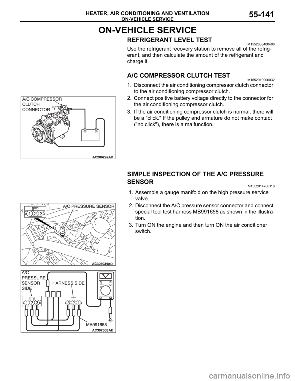
A/C COMPRESSOR CLUTCH TESTM1552019900032
1. Disconnect the air conditioning compressor clutch connector
to the air conditioning compressor clutch.
2. Connect positive battery voltage directly to the connector for
the air conditioning compressor clutch.
3. If the air conditioning compressor clutch is normal, there will
be a "click." If the pulley and armature do not make contact
("no click"), there is a malfunction.
SIMPLE INSPECTION OF THE A/C PRESSURE
SENSOR
M1552014700118
1. Assemble a gauge manifold on the high pressure service
valve.
2. Disconnect the A/C pressure sensor connector and connect
special tool test harness MB991658 as shown in the illustra-
tion.
3. Turn ON the engine and then turn ON the air conditioner
switch.
Page 844 of 1500

ON-VEHICLE SERVICE
HEATER, AIR CONDITIONING AND VENTILATION55-143
PERFORMANCE TEST M1552001400526
The vehicles to be tested should be parked out of direct sun-
light.
1. Close the high and low-pressure valve of the gauge
manifold.
2. Connect the charging hose (blue) to the low-pressure valve
and connect the charging hose (red) to the high-pressure
valve of the gauge manifold.
3. Install the quick joint (for low-pressure) to the charging hose
(blue), and connect the quick joint (for high-pressure) to the
charging hose (red).
To connect the quick joint, press section A firmly
against the service valve until a click is heard.
When connecting, run your hand along the hose while
pressing to ensure that there are no bends in the hose.
4. Connect the quick joint (for low-pressure) to the
low-pressure service valve and connect the quick joint (for
high-pressure) to the high-pressure service valve.
NOTE: The high-pressure service valve is on the A/C pipe
and the low-pressure service valve is on the suction hose.
5. Start the engine.
6. Set the A/C controls as follows:
A/C switch: A/C ON position
Mode selection: FACE position
Temperature control: MAXIMUM COOLING position
Air selection: RECIRCULATION position
Blower switch: Maximum air volume
7. Adjust engine speed to 1,500 r/min with A/C clutch engaged.
8. Engine should be warmed up with doors and windows
closed.
9. Insert a thermometer in the center air outlet and operate the
engine for 20 minutes.
NOTE: If the A/C clutch cycles, take the reading before the
clutch disengages.
10.Note the discharge air temperature.
PERFORMANCE TEMPERATURE CHART
GARAGE AMBIENT AIR TEMPERATURE C
(
F)20 (68) 25 (77) 30 (86) 35 (95)
Discharge air temperature
C (F) 1 (34) 6 (43)
Compressor high pressure kPa (psi) 1275 (185)
1863 (270)
Compressor low pressure kPa (psi) 49 (7.1)
294 (42.7)
Page 845 of 1500
ON-VEHICLE SERVICE
HEATER, AIR CONDITIONING AND VENTILATION55-144
REFRIGERANT LEAK INSPECTION PROCEDUREM1552001500299
LEAK INSPECTION
1. Check for leakage using Special Tool at the following loca-
tions.
Good ventilation is necessary during the leak inspection. If
the surrounding air is contaminated with refrigerant gas,
the inspection readings will not be accurate.
LEAK CHECK LOCATION
1. SUCTION HOSE TO TX VALVE
2. LIQUID TUBE TO TX VALVE
3. SUCTION HOSE JOINT
4. LOW PRESSURE SERVICE
VA LV E
5. HIGH PRESSURE SERVICE
VA LV E
6. CONDENSER-DISCHARGE
HOSE JOINT
7. PRESSURE SENSOR8. CONDENSER-LIQUID TUBE
JOINT
9. COMPRESSOR-SUCTION HOSE
JOINT
10. COMPRESSOR-DISCHARGE
HOSE JOINT
11. UNDER COMPRESSOR CLUTCH
12. AROUND MODULATOR CAP
13. TX VALVE TO EVAPORATOR
JOINT LEAK CHECK LOCATION
Page 847 of 1500

ON-VEHICLE SERVICE
HEATER, AIR CONDITIONING AND VENTILATION55-146
Sharper bends will reduce the flow of refrigerant. The flexible
hose lines should be routed so that they are at least 80 mm
(3.1 inches) from the exhaust manifold. It is good practice to
inspect all flexible hose lines at least once a year to make sure
they are in good condition and properly routed.
On standard plumbing fittings with O-rings, these O-rings are
not reusable.
AIR CONDITIONING NOISE TEST
You must first know the conditions when the noise occurs.
These conditions are: weather, vehicle speed, in gear or neu-
tral, engine temperature or any other special conditions.
Noises that develop during A/C operation can often be mislead-
ing. For example: what sounds like a failed front bearing or
connecting rod, may be caused by loose bolts, nuts, mounting
brackets, or a loose clutch assembly. Verify accessory drive
belt tension (power steering or generator).
Improper accessory drive belt tension can cause a misleading
noise when the compressor is engaged and little or no noise
when the compressor is disengaged.
Drive belts are speed-sensitive. That is, at different engine
speeds, and depending upon belt tension, belts can develop
unusual noises that are often mistaken for mechanical prob-
lems within the compressor.
Normal air conditioning operation will generate some level of
operational noise. To judge what is normal and abnormal,
requires an understanding of the air conditioning system. This
test is to detail the most common noise complaints and the
repair methods.
VEHICLE CONDITION
1. Ensure the system is not over or under charged.(Refer to
P.55-142).
2. Tighten all compressor mounting bolts, clutch mounting
bolts and compressor drive belt.
3. Inspect layout of the system is correct, ie no interference
between hoses and all retaining clamps are in place.
Page 848 of 1500

ON-VEHICLE SERVICE
HEATER, AIR CONDITIONING AND VENTILATION55-147
TEST PROCEDURES
1. Select a quiet area for testing.
2. Duplicate problem (customer complaint) as much as
possible.
3. Judge if the noise is abnormal (ie. it is important to
understand the characteristics of the vehicle and its normal
state to judge what is abnormal) - Compare with similar
vehicle if necessary.
4. Detail what and how noise occurs.
5. Find the noise source and verify its transmission by isolating
the subject part from the vehicle.
6. Repair the problem.
7. Explain and report your findings.
DETAILS OF A/C NOISE
POSSIBLE CAUSES, CHECKS AND REPAIRS
NOISE DESCRIPTION WHEN IT OCCURS SOURCE OF NOISE
Rumbling (Bearing noise) With A/C On or Off Magnetic clutch, idler pulley
Clang-Clack noise When compressor is engaged Magnetic clutch operation
Squawking (Belt sliding noise) When compressor is engaged V-belt
Whistling or Whooping noise Immediately after the A/C is
engaged.Expansion valve
Hissing or swishing noise When A/C is engaged, but
decreases as flow is stable Refrigerant flow
Rattling (Internal compressor) When compressor is operating Compressor internal part
Wooing (Resonant noise) With A/C On, occurs at certain
speed.Resonance of accessories
Cooing (Discharge pulsation
noise)With A/C On or Off Resonating noise with the vehicle
body
NOISE DESCRIPTION POSSIBLE CAUSE CHECK REPAIR
Rumbling (Bearing
noise)Bearing damage in rotor Manual rotation of bearing Replace compressor
Rotor slipping on boss Wear on compressor boss
surfaceReplace compressor
Bearing damage in pulley Check alignment between
pulleysReplace compressor
Clang-Clack noise Hub to stator misaligned Wear on inner clutch face Replace compressor
Gap between clutch
surface is too largeCheck Air gap is within
specificationReplace compressor
Squawking (Belt sliding
noise)Oil/water between the belt
and rotor surfaceOil and water
contaminationClean
Low belt tension Belt tension Reset or Replace belt and
set tension to correct
specification
Whistling or Whooping
noiseVibration of expansion
valveExpansion valve Replace TX valve
Page 850 of 1500

ON-VEHICLE SERVICE
HEATER, AIR CONDITIONING AND VENTILATION55-149
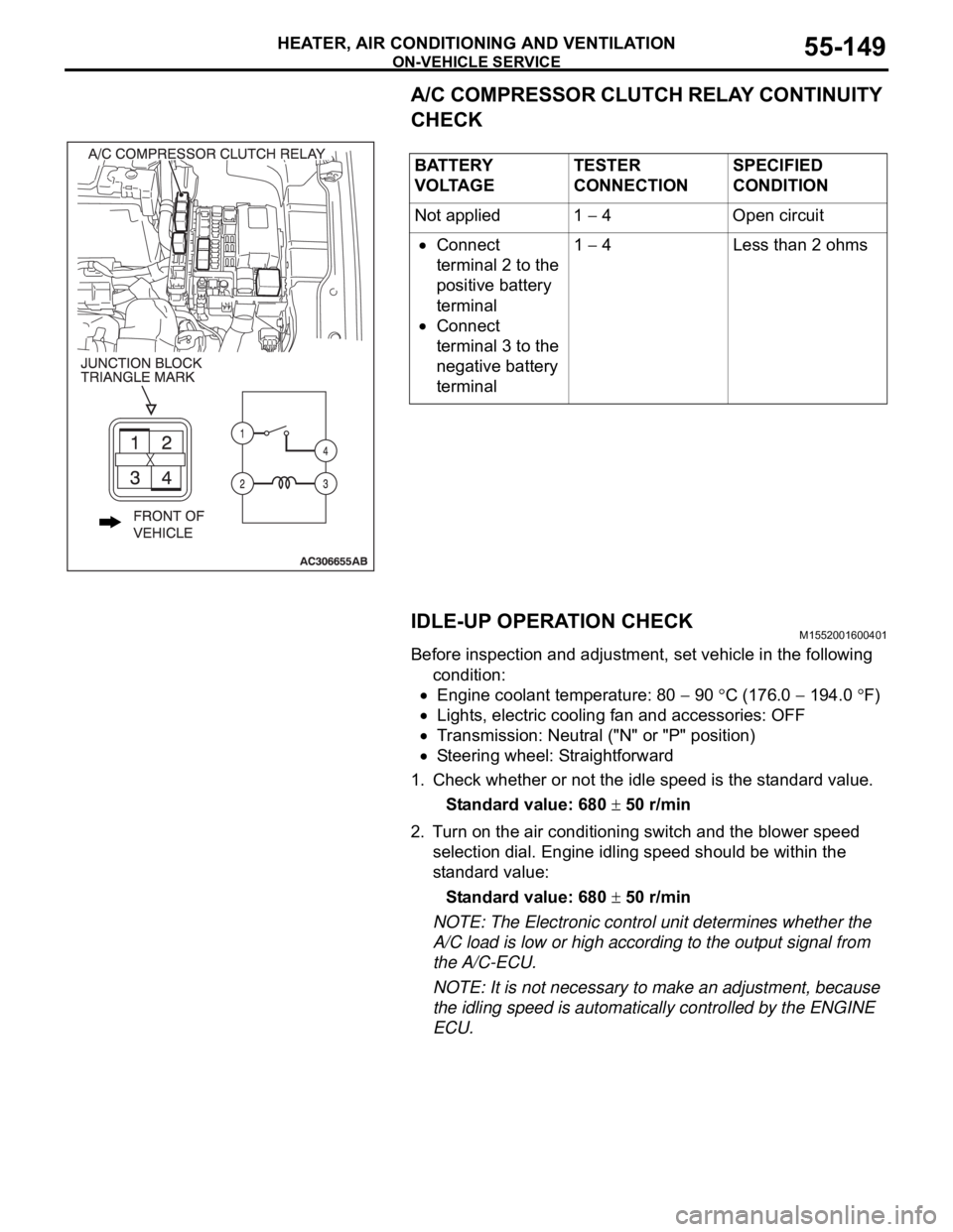
A/C COMPRESSOR CLUTCH RELAY CONTINUITY
CHECK
IDLE-UP OPERATION CHECK
M1552001600401
Before inspection and adjustment, set vehicle in the following
condition:
Engine coolant temperature: 80 90 C (176.0 194.0 F)
Lights, electric cooling fan and accessories: OFF
Transmission: Neutral ("N" or "P" position)
Steering wheel: Straightforward
1. Check whether or not the idle speed is the standard value.
Standard value: 680
50 r/min
2. Turn on the air conditioning switch and the blower speed
selection dial. Engine idling speed should be within the
standard value:
Standard value: 680
50 r/min
NOTE: The Electronic control unit determines whether the
A/C load is low or high according to the output signal from
the A/C-ECU.
NOTE: It is not necessary to make an adjustment, because
the idling speed is automatically controlled by the ENGINE
ECU. BATTERY
V O LTA G ETESTER
CONNECTIONSPECIFIED
CONDITION
Not applied 1
4 Open circuit
Connect
terminal 2 to the
positive battery
terminal
Connect
terminal 3 to the
negative battery
terminal1
4 Less than 2 ohms
Page 853 of 1500
Page 867 of 1500
COMPRESSOR ASSEMBLY AND DRIVE BELT
HEATER, AIR CONDITIONING AND VENTILATION55-166
INSPECTIONM1552014301083
COMPRESSOR AIR CONDITIONING
COMPRESSOR CLUTCH OPERATION CHECK
Connect the compressor connector terminal to the battery posi-
tive (+) terminal and ground the battery’s negative (-) terminal
to the compressor unit. At that time, the air conditioning com-
pressor clutch should make a definite operating sound.
.
AIR GAP ADJUSTMENT
Check whether or not the air gap of the clutch is within the stan-
dard value.
Standard value:
0.35
0.60mm
NOTE: If there is a deviation of the air gap from the standard
value, assess the operation of the clutch and replace the com-
pressor assembly as required.