Page 1098 of 1500
DOOR
BODY42-31
(2) Adjustment by using the striker (toward the outside of the
vehicle)
Use special tools MB990211 and MB990243 to pull the
striker toward the outside of the vehicle.
(3) Adjustment by using shims (forward and rearward)
Increase or decrease the number of shims so that the
striker engages with the door latch properly.
DOOR WINDOW GLASS ADJUSTMENTM1423001000349
Check that the door glass moves while contacting the door
glass channel when it is raised and lowered fully. If not, adjust
the door window according to the following procedures.
1. Remove the door trim assembly (Refer to GROUP 52A,
Door trim P.52A-14).
2. Remove the waterproof film (Refer to P.42-52).
3. Loosen the door window glass mounting bolts.
4. Adjust the position of the door window glass so that it is
aligned with the runchannel. On completion, tighten the door
window glass mounting bolts.
Page 1124 of 1500
DOOR
BODY42-57
INSTALLATION SERVICE POINTS
.
>>A<< WATERPROOF FILM INSTALLATION
When the waterproof film is adhered, be careful that
3M
AAD Part number 8633 or equivalent can pass under
the inner panel water drain hole.
1. Stick the waterproof film to the door in sequence as shown.
2. Press the waterproof film toward the arrow in the illustration.
.
Page 1153 of 1500

SPECIFICATIONS
BODY42-86
SPECIFICATIONS
FASTENER TIGHTENING SPECIFICATIONSM1421005300216
ITEM SPECIFICATION
Hood
Hood hinge bolt (body side) 12
2 Nm (102 22 in-lb)
Hood hinge bolt (hood side) 12
2 Nm (102 22 in-lb)
Hood hinge nut (body side) 12
2 Nm (102 22 in-lb)
Hood latch bolt 9.0
2.0 Nm (80 17 in-lb)
Strut tower bar
Strut tower bar nut 12
2 Nm (102 22 in-lb)
Strut tower bar bracket nut 48
7 Nm (36 5 ft-lb)
Door
Door check bolt (body side) 9.0
2.0 Nm (80 17 in-lb)
Door check bolt (door side) 5.0
1.0 Nm (44 9 in-lb)
Door hinge bolt (body side) 27
5 Nm (20 4 ft-lb)
Door hinge bolt (door side) 21
4 Nm (16 2 ft-lb)
Door outside handle bolt 5.0
1.0 Nm (44 9 in-lb)
Door latch assembly screw 5.9
1.0 Nm (52 9 in-lb)
Door switch screw 3.9
1.0 Nm (35 8 in-lb)
Striker screw 24
3 Nm (18 2 ft-lb)
Trunk lid
Trunk lid hinge bolt (body side) 13
2 Nm ( 111 22 in-lb)
Trunk lid hinge bolt (trunk lid side) 13
2 Nm ( 111 22 in-lb)
Trunk lid hinge nut (trunk lid side) 13
2 Nm ( 111 22 in-lb)
Trunk lid latch bolt 9.0
2.0 Nm (80 17 in-lb)
Trunk lid striker bolt 5.0
1.0 Nm (44 9 in-lb)
Sunroof
Roof lid glass screw 4.0
0.5 Nm (36 4 in-lb)
Sunroof drip plate screw 2.0 N
m (18 in-lb)
Sunroof housing screw 2.0 N
m (18 in-lb)
Sunroof motor bolt 5.4 N
m (48 in-lb)
Loose panel
Cowl top cover outer bolt 11
2 Nm (98 17 in-lb)
Front end structure bar bolt 22
4 Nm (16 2 ft-lb)
12
2 Nm (102 22 in-lb)
11
2 Nm (98 17 in-lb)
Front floor backbone brace bolt 22
4 Nm (16 2 ft-lb)
Upper frame to front pillar brace bolt 22
4 Nm (16 2 ft-lb)
Page 1191 of 1500
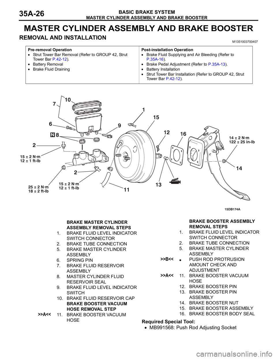
MASTER CYLINDER ASSEMBLY AND BRAKE BOOSTER
BASIC BRAKE SYSTEM35A-26
MASTER CYLINDER ASSEMBLY AND BRAKE BOOSTER
REMOVAL AND INSTALLATIONM1351003700407
Required Special Tool:
MB991568: Push Rod Adjusting Socket
Pre-removal Operation
Strut Tower Bar Removal (Refer to GROUP 42, Strut
To w e r B a r P.42-12).
Battery Removal
Brake Fluid DrainingPost-installation Operation
Brake Fluid Supplying and Air Bleeding (Refer to
P.35A-16).
Brake Pedal Adjustment (Refer to P.35A-13).
Battery Installation
Strut Tower Bar Installation (Refer to GROUP 42, Strut
Tower Bar P.42-12).
BRAKE MASTER CYLINDER
ASSEMBLY REMOVAL STEPS
1. BRAKE FLUID LEVEL INDICATOR
SWITCH CONNECTOR
2. BRAKE TUBE CONNECTION
5. BRAKE MASTER CYLINDER
ASSEMBLY
6. SPRING PIN
7. BRAKE FLUID RESERVOIR
ASSEMBLY
8. MASTER CYLINDER FLUID
RESERVOIR SEAL
9. BRAKE FLUID LEVEL INDICATOR
SWITCH
10. BRAKE FLUID RESERVOIR CAP
BRAKE BOOSTER VACUUM
HOSE REMOVAL STEP
>>A<<11. BRAKE BOOSTER VACUUM
HOSE BRAKE BOOSTER ASSEMBLY
REMOVAL STEPS
1. BRAKE FLUID LEVEL INDICATOR
SWITCH CONNECTOR
2. BRAKE TUBE CONNECTION
5. BRAKE MASTER CYLINDER
ASSEMBLY
>>B<
AMOUNT CHECK AND
ADJUSTMENT
>>A<<11. BRAKE BOOSTER VACUUM
HOSE
12. BRAKE BOOSTER PIN
13. BRAKE BOOSTER PIN
ASSEMBLY
14. BRAKE BOOSTER NUT
15. BRAKE BOOSTER ASSEMBLY
16. BRAKE BOOSTER BODY SEAL
Page 1222 of 1500
00-1
GROUP 00
GENERAL
CONTENTS
HOW TO USE THIS MANUAL . . . . . .00-3
TROUBLESHOOTING GUIDELINES00-6
HOW TO USE TROUBLESHOOTING /
INSPECTION SERVICE POINTS. . . .00-7
TROUBLESHOOTING CONTENTS . . . . . . 00-7
HOW TO USE THE INSPECTION
PROCEDURES . . . . . . . . . . . . . . . . . . . . . . 00-9
CONNECTOR MEASUREMENT SERVICE
POINTS . . . . . . . . . . . . . . . . . . . . . . . . . . . . 00-11
CONNECTOR INSPECTION SERVICE
POINTS . . . . . . . . . . . . . . . . . . . . . . . . . . . . 00-13
HOW TO COPE WITH INTERMITTENT
MALFUNCTIONS . . . . . . . . . . . . . . . . . . . . 00-14
INSPECTION SERVICE POINTS
FOR A BLOWN FUSE . . . . . . . . . . . . . . . . 00-16
HOW TO TREAT CURRENT TROUBLE . . 00-16
HOW TO TREAT PAST TROUBLE . . . . . . 00-16
AFFILIATED DTC REFERENCE
TABLE . . . . . . . . . . . . . . . . . . . . . . . .00-17
VEHICLE IDENTIFICATION . . . . . . .00-18
VEHICLE IDENTIFICATION NUMBER . . . 00-18
VEHICLE INFORMATION NUMBER LIST 00-19
VEHICLE COMPLIANCE PLATE . . . . . . . . 00-19
VEHICLE DATA PLATE . . . . . . . . . . . . . . . 00-20
AUSTRALIAN DESIGN RULES . . . . . . . . . 00-20OPTION CODES . . . . . . . . . . . . . . . . . . . . . 00-21
EXPORT CODES . . . . . . . . . . . . . . . . . . . . 00-21
TYRE AND LOADING PLACARD . . . . . . . . 00-21
ENGINE MODEL STAMPING . . . . . . . . . . . 00-22
PRECAUTIONS BEFORE SERVICE .00-22
SUPPLEMENTAL RESTRAINT
SYSTEM (SRS . . . . . . . . . . . . . . . . . . . . . . 00-22
HOW TO PERFORM VEHICLE
IDENTIFICATION NUMBER (VIN) WRITING00-23
SERVICING ELECTRICAL SYSTEM . . . . . 00-24
VEHICLE WASHING . . . . . . . . . . . . . . . . . . 00-24
APPLICATION OF ANTI-CORROSION
AGENTS AND UNDERCOATS . . . . . . . . . . 00-25
DIAGNOSTIC TOOL (MUT-III) . . . . . . . . . . 00-25
TOWING AND HOISTING. . . . . . . . . .00-26
GENERAL DATA AND
SPECIFICATIONS . . . . . . . . . . . . . . .00-31
TIGHTENING TORQUE . . . . . . . . . . .00-32
LUBRICATION AND MAINTENANCE 00-34
RECOMMENDED LUBRICANTS AND
LUBRICANT CAPACITIES TABLE . .00-35
Continued on next page
Page 1242 of 1500
VEHICLE IDENTIFICATION
GENERAL00-21
OPTION CODES (380 Series)
EXPORT CODES
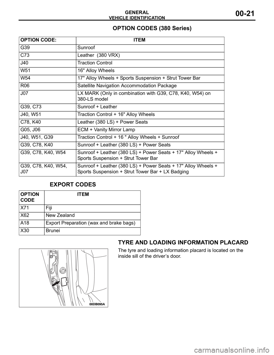
TYRE AND LOADING INFORMATION PLACARD
The tyre and loading information placard is located on the
inside sill of the driver’s door. OPTION CODE: ITEM
G39 Sunroof
C73 Leather (380 VRX)
J40 Traction Control
W51 16" Alloy Wheels
W54 17" Alloy Wheels + Sports Suspension + Strut Tower Bar
R06 Satellite Navigation Accommodation Package
J07 LX MARK (Only in combination with G39, C78, K40, W54) on
380-LS model
G39, C73 Sunroof + Leather
J40, W51 Traction Control + 16" Alloy Wheels
C78, K40 Leather (380 LS) + Power Seats
G05, J06 ECM + Vanity Mirror Lamp
J40, W51, G39 Traction Control + 16 " Alloy Wheels + Sunroof
G39, C78, K40 Sunroof + Leather (380 LS) + Power Seats
G39, C78, K40, W54 Sunroof + Leather (380 LS) + Power Seats + 17" Alloy Wheels +
Sports Suspension + Strut Tower Bar
G39, C78, K40, W54,
J07Sunroof + Leather (380 LS) + Power Seats + 17" Alloy Wheels +
Sports Suspension + Strut Tower Bar + LX Badging
OPTION
CODE ITEM
X71 Fiji
X62 New Zealand
A18 Export Preparation (wax and brake bags)
X30 Brunei
Page 1247 of 1500
TOWING AND HOISTING
GENERAL00-26
TOWING AND HOISTINGM1001000800380
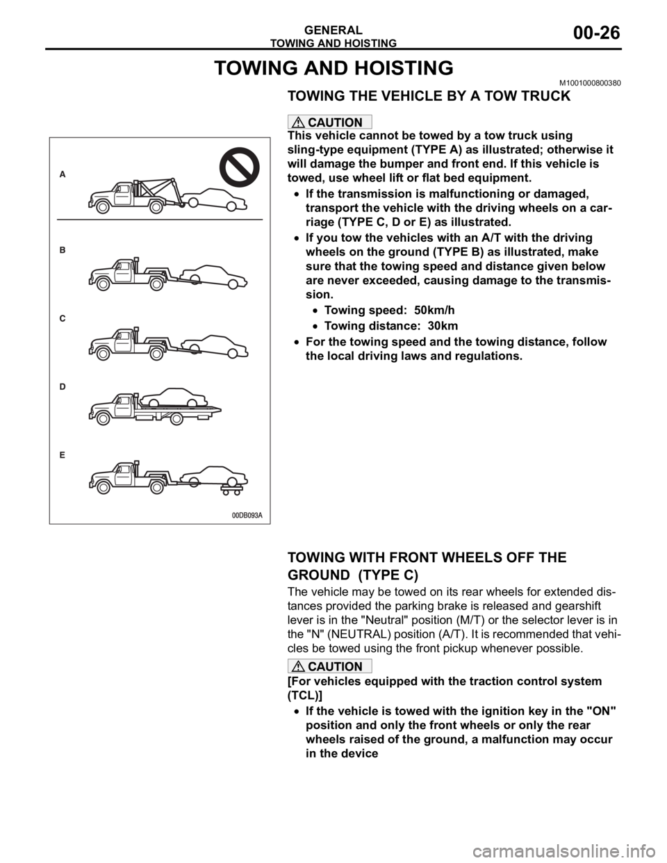
TOWING THE VEHICLE BY A TOW TRUCK
.
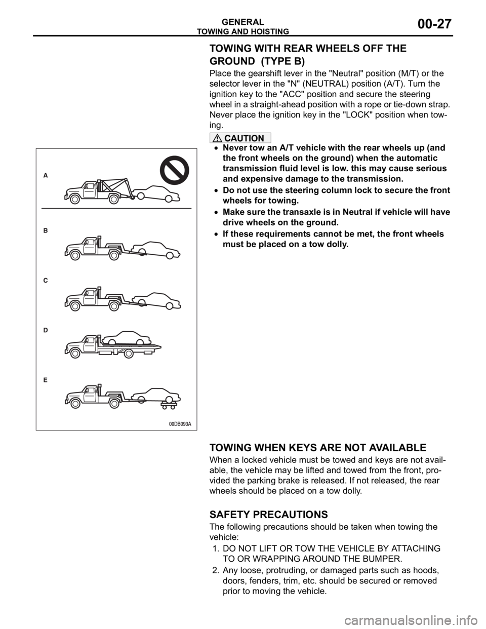
This vehicle cannot be towed by a tow truck using
sling-type equipment (TYPE A) as illustrated; otherwise it
will damage the bumper and front end. If this vehicle is
towed, use wheel lift or flat bed equipment.
If the transmission is malfunctioning or damaged,
transport the vehicle with the driving wheels on a car-
riage (TYPE C, D or E) as illustrated.
If you tow the vehicles with an A/T with the driving
wheels on the ground (TYPE B) as illustrated, make
sure that the towing speed and distance given below
are never exceeded, causing damage to the transmis-
sion.
Towing speed: 50km/h
Towing distance: 30km
For the towing speed and the towing distance, follow
the local driving laws and regulations.
.
TOWING WITH FRONT WHEELS OFF THE
GROUND (TYPE C)
The vehicle may be towed on its rear wheels for extended dis-
tances provided the parking brake is released and gearshift
lever is in the "Neutral" position (M/T) or the selector lever is in
the "N" (NEUTRAL) position (A/T). It is recommended that vehi-
cles be towed using the front pickup whenever possible.
[For vehicles equipped with the traction control system
(TCL)]
If the vehicle is towed with the ignition key in the "ON"
position and only the front wheels or only the rear
wheels raised of the ground, a malfunction may occur
in the device
.
Page 1248 of 1500
TOWING AND HOISTING
GENERAL00-27
TOWING WITH REAR WHEELS OFF THE
GROUND (TYPE B)
Place the gearshift lever in the "Neutral" position (M/T) or the
selector lever in the "N" (NEUTRAL) position (A/T). Turn the
ignition key to the "ACC" position and secure the steering
wheel in a straight-ahead position with a rope or tie-down strap.
Never place the ignition key in the "LOCK" position when tow-
ing.
Never tow an A/T vehicle with the rear wheels up (and
the front wheels on the ground) when the automatic
transmission fluid level is low. this may cause serious
and expensive damage to the transmission.
Do not use the steering column lock to secure the front
wheels for towing.
Make sure the transaxle is in Neutral if vehicle will have
drive wheels on the ground.
If these requirements cannot be met, the front wheels
must be placed on a tow dolly.
.
TOWING WHEN KEYS ARE NOT AVAILABLE
When a locked vehicle must be towed and keys are not avail-
able, the vehicle may be lifted and towed from the front, pro-
vided the parking brake is released. If not released, the rear
wheels should be placed on a tow dolly.
.
SAFETY PRECAUTIONS
The following precautions should be taken when towing the
vehicle:
1. DO NOT LIFT OR TOW THE VEHICLE BY ATTACHING
TO OR WRAPPING AROUND THE BUMPER.
2. Any loose, protruding, or damaged parts such as hoods,
doors, fenders, trim, etc. should be secured or removed
prior to moving the vehicle.