Page 1100 of 1500
DOOR
BODY42-33
POWER WINDOW OPERATING CURRENT CHECKM1429001100195
1. Remove the power window fuse and connect an ammeter
as shown in the illustration.
2. When the power window switch is pressed in the “UP”
position, a large amount of current flows from the time the
window starts to close until it is fully closed, Measure the
current during this time
Standard value (A): 5
1A [Power supply voltage
14.5
0.5V, 25C (77F)]
3. If the operation current is outside the standard value, refer to
GROUP 54B, SWS Diagnosis P.54B-61.
POWER WINDOW RELAY CHECKM1429001800213
BATTERY
VOLTAGETESTER
CONNECTIONSPECIFIED
CONDITION
Not applied 4
5 Open circuit
Connect terminal
No. 3 and the
negative battery
terminal.
Connect terminal
No. 1 and the
positive battery
terminal.4
5 Less than 2 ohms
Page 1143 of 1500

SUNROOF ASSEMBLY
BODY42-76
SUNROOF TIMER FUNCTION CHECKM1426004300100
Keep the door closed, turn OFF the ignition switch and check to
see if the sunroof can be operated for 30 seconds after that. If
not, perform troubleshooting (Refer to GROUP 54B, SWS
Diagnosis P.54B-57).
SUNROOF FIT ADJUSTMENTM1426001000285
1. Fully close the roof lid glass.
2. Fully open the sunshade.
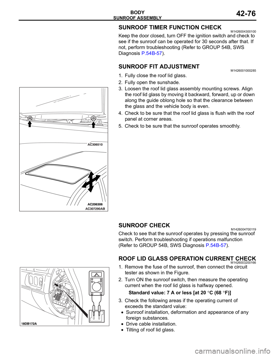
3. Loosen the roof lid glass assembly mounting screws. Align
the roof lid glass by moving it backward, forward, up or down
along the guide oblong hole so that the clearance between
the glass and the vehicle body is even.
4. Check to be sure that the roof lid glass is flush with the roof
panel at corner areas.
5. Check to be sure that the sunroof operates smoothly.
SUNROOF CHECKM1426004700119
Check to see that the sunroof operates by pressing the sunroof
switch. Perform troubleshooting if operations malfunction
(Refer to GROUP 54B, SWS Diagnosis P.54B-57).
ROOF LID GLASS OPERATION CURRENT CHECKM1426003200166
1. Remove the fuse of the sunroof, then connect the circuit
tester as shown in the Figure.
2. Turn ON the sunroof switch, then measure the operating
current when the roof lid glass is halfway opened.
Standard value: 7 A or less [at 20
C (68 F)]
3. Check the following areas if the operating current of
exceeds the standard value:
Sunroof installation, deformation and appearance of any
foreign substances.
Drive cable installation.
Tilting of roof lid glass.
Page 1222 of 1500

00-1
GROUP 00
GENERAL
CONTENTS
HOW TO USE THIS MANUAL . . . . . .00-3
TROUBLESHOOTING GUIDELINES00-6
HOW TO USE TROUBLESHOOTING /
INSPECTION SERVICE POINTS. . . .00-7
TROUBLESHOOTING CONTENTS . . . . . . 00-7
HOW TO USE THE INSPECTION
PROCEDURES . . . . . . . . . . . . . . . . . . . . . . 00-9
CONNECTOR MEASUREMENT SERVICE
POINTS . . . . . . . . . . . . . . . . . . . . . . . . . . . . 00-11
CONNECTOR INSPECTION SERVICE
POINTS . . . . . . . . . . . . . . . . . . . . . . . . . . . . 00-13
HOW TO COPE WITH INTERMITTENT
MALFUNCTIONS . . . . . . . . . . . . . . . . . . . . 00-14
INSPECTION SERVICE POINTS
FOR A BLOWN FUSE . . . . . . . . . . . . . . . . 00-16
HOW TO TREAT CURRENT TROUBLE . . 00-16
HOW TO TREAT PAST TROUBLE . . . . . . 00-16
AFFILIATED DTC REFERENCE
TABLE . . . . . . . . . . . . . . . . . . . . . . . .00-17
VEHICLE IDENTIFICATION . . . . . . .00-18
VEHICLE IDENTIFICATION NUMBER . . . 00-18
VEHICLE INFORMATION NUMBER LIST 00-19
VEHICLE COMPLIANCE PLATE . . . . . . . . 00-19
VEHICLE DATA PLATE . . . . . . . . . . . . . . . 00-20
AUSTRALIAN DESIGN RULES . . . . . . . . . 00-20OPTION CODES . . . . . . . . . . . . . . . . . . . . . 00-21
EXPORT CODES . . . . . . . . . . . . . . . . . . . . 00-21
TYRE AND LOADING PLACARD . . . . . . . . 00-21
ENGINE MODEL STAMPING . . . . . . . . . . . 00-22
PRECAUTIONS BEFORE SERVICE .00-22
SUPPLEMENTAL RESTRAINT
SYSTEM (SRS . . . . . . . . . . . . . . . . . . . . . . 00-22
HOW TO PERFORM VEHICLE
IDENTIFICATION NUMBER (VIN) WRITING00-23
SERVICING ELECTRICAL SYSTEM . . . . . 00-24
VEHICLE WASHING . . . . . . . . . . . . . . . . . . 00-24
APPLICATION OF ANTI-CORROSION
AGENTS AND UNDERCOATS . . . . . . . . . . 00-25
DIAGNOSTIC TOOL (MUT-III) . . . . . . . . . . 00-25
TOWING AND HOISTING. . . . . . . . . .00-26
GENERAL DATA AND
SPECIFICATIONS . . . . . . . . . . . . . . .00-31
TIGHTENING TORQUE . . . . . . . . . . .00-32
LUBRICATION AND MAINTENANCE 00-34
RECOMMENDED LUBRICANTS AND
LUBRICANT CAPACITIES TABLE . .00-35
Continued on next page
Page 1231 of 1500
HOW TO USE TROUBLESHOOTING/INSPECTION SERVICE POINTS
GENERAL00-10
CURRENT TROUBLE
Indicates that the trouble is currently present. Carry
out troubleshooting as described in the applicable
inspection procedure.
PAST TROUBLE
Indicates that the trouble is historic, but normal oper-
ation has been restored. Observe the applicable
inspection procedure with particular emphasis on
connector(s) and wiring harness.
HARNESS INSPECTION
Check for an open or short circuit in the harness
between the terminals which were faulty according to
the connector measurements. Carry out this inspec-
tion while referring to GROUP 00E, Harness Con-
nector Inspection P.00E-2. Here, “Check harness
between power supply and terminal xx” also includes
checking for blown fuse. For inspection service
points when there is a blown fuse, refer to "Inspec-
tion Service Points for a Blown Fuse P.00-16."
Page 1237 of 1500

HOW TO USE TROUBLESHOOTING/INSPECTION SERVICE POINTS
GENERAL00-16
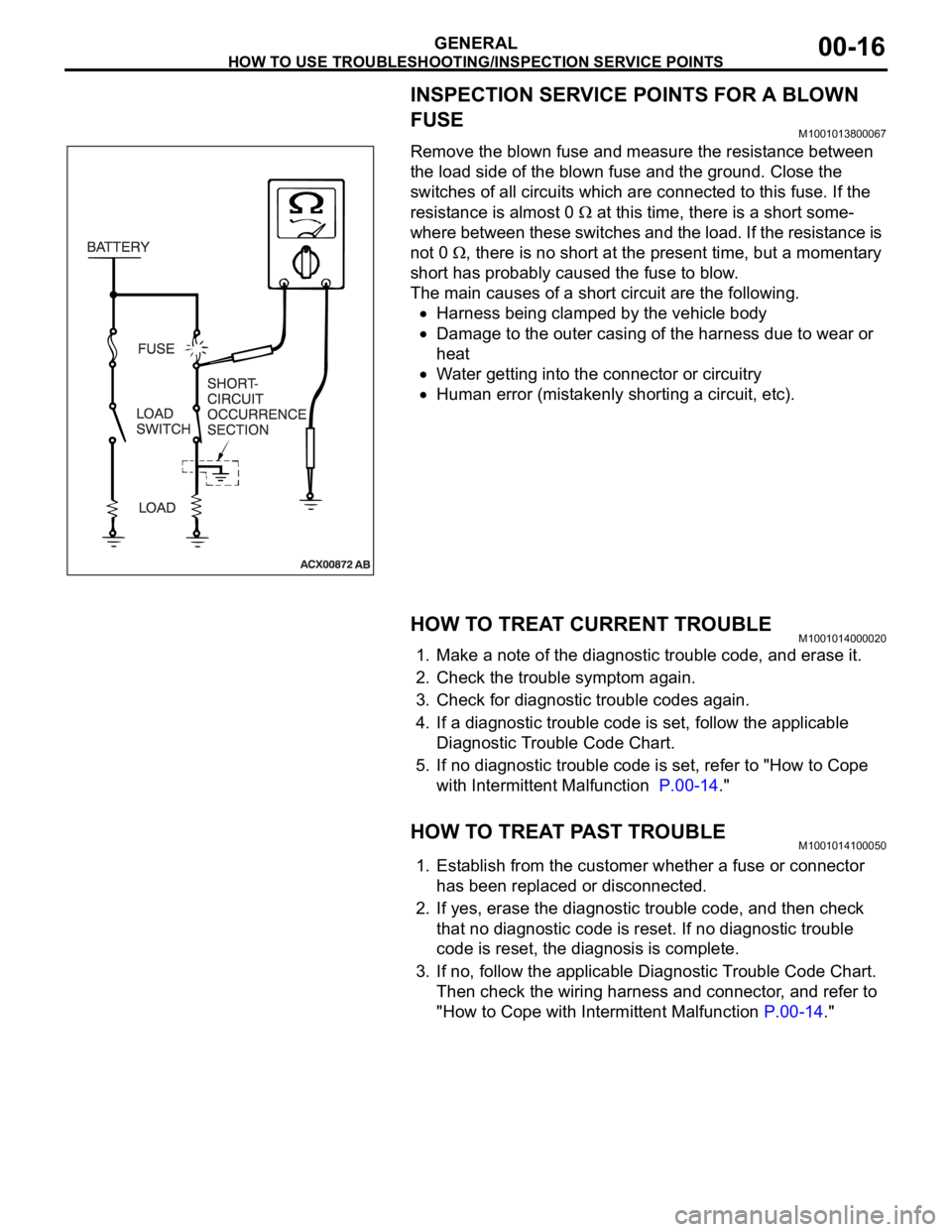
INSPECTION SERVICE POINTS FOR A BLOWN
FUSE
M1001013800067
Remove the blown fuse and measure the resistance between
the load side of the blown fuse and the ground. Close the
switches of all circuits which are connected to this fuse. If the
resistance is almost 0
at this time, there is a short some-
where between these switches and the load. If the resistance is
not 0
, there is no short at the present time, but a momentary
short has probably caused the fuse to blow.
The main causes of a short circuit are the following.
Harness being clamped by the vehicle body
Damage to the outer casing of the harness due to wear or
heat
Water getting into the connector or circuitry
Human error (mistakenly shorting a circuit, etc).
HOW TO TREAT CURRENT TROUBLEM1001014000020
1. Make a note of the diagnostic trouble code, and erase it.
2. Check the trouble symptom again.
3. Check for diagnostic trouble codes again.
4. If a diagnostic trouble code is set, follow the applicable
Diagnostic Trouble Code Chart.
5. If no diagnostic trouble code is set, refer to "How to Cope
with Intermittent Malfunction P.00-14."
HOW TO TREAT PAST TROUBLEM1001014100050
1. Establish from the customer whether a fuse or connector
has been replaced or disconnected.
2. If yes, erase the diagnostic trouble code, and then check
that no diagnostic code is reset. If no diagnostic trouble
code is reset, the diagnosis is complete.
3. If no, follow the applicable Diagnostic Trouble Code Chart.
Then check the wiring harness and connector, and refer to
"How to Cope with Intermittent Malfunction P.00-14."
Page 1372 of 1500
AUTO-CRUISE CONTROL
ENGINE AND EMISSION CONTROL17-41
STEP 8. Check the harness wire between stoplamp switch
connector C-30 terminal 2 and fuse number 11 at the relay
box at engine compartment for damage.
Q: Is the harness wire in good condition?
YES : Go to Step 9.
NO : Repair the damaged harness wire. Then go to Step
22.
STEP 9. Check the fuse number 11 at the relay box at
engine compartment.
Q: Is the fuse in good condition?
YES : Go to Step 10.
NO : Check the stoplamp system harness and replace the
fuse. Then go to Step 22.
Page:
< prev 1-8 9-16 17-24