2005 MITSUBISHI 380 Trunk lock
[x] Cancel search: Trunk lockPage 1026 of 1500
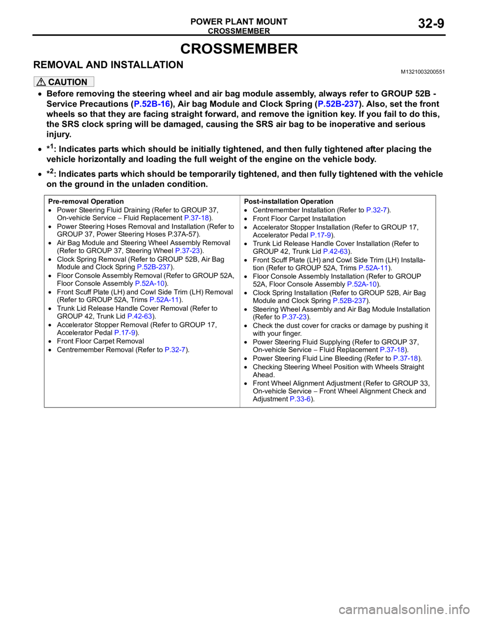
CROSSMEMBER
POWER PLANT MOUNT32-9
CROSSMEMBER
REMOVAL AND INSTALLATIONM1321003200551
Before removing the steering wheel and air bag module assembly, always refer to GROUP 52B -
Service Precautions (P.52B-16), Air bag Module and Clock Spring (P.52B-237). Also, set the front
wheels so that they are facing straight forward, and remove the ignition key. If you fail to do this,
the SRS clock spring will be damaged, causing the SRS air bag to be inoperative and serious
injury.
*1: Indicates parts which should be initially tightened, and then fully tightened after placing the
vehicle horizontally and loading the full weight of the engine on the vehicle body.
*2: Indicates parts which should be temporarily tightened, and then fully tightened with the vehicle
on the ground in the unladen condition.
Pre-removal Operation
Power Steering Fluid Draining (Refer to GROUP 37,
On-vehicle Service Fluid Replacement P.37-18).
Power Steering Hoses Removal and Installation (Refer to
GROUP 37, Power Steering Hoses P.37A-57).
Air Bag Module and Steering Wheel Assembly Removal
(Refer to GROUP 37, Steering Wheel P.37-23).
Clock Spring Removal (Refer to GROUP 52B, Air Bag
Module and Clock Spring P.52B-237).
Floor Console Assembly Removal (Refer to GROUP 52A,
Floor Console Assembly P.52A-10).
Front Scuff Plate (LH) and Cowl Side Trim (LH) Removal
(Refer to GROUP 52A, Trims P.52A-11).
Trunk Lid Release Handle Cover Removal (Refer to
GROUP 42, Trunk Lid P.42-63).
Accelerator Stopper Removal (Refer to GROUP 17,
Accelerator Pedal P.17-9).
Front Floor Carpet Removal
Centremember Removal (Refer to P.32-7).Post-installation Operation
Centremember Installation (Refer to P.32-7).
Front Floor Carpet Installation
Accelerator Stopper Installation (Refer to GROUP 17,
Accelerator Pedal P.17-9).
Trunk Lid Release Handle Cover Installation (Refer to
GROUP 42, Trunk Lid P.42-63).
Front Scuff Plate (LH) and Cowl Side Trim (LH) Installa-
tion (Refer to GROUP 52A, Trims P.52A-11).
Floor Console Assembly Installation (Refer to GROUP
52A, Floor Console Assembly P.52A-10).
Clock Spring Installation (Refer to GROUP 52B, Air Bag
Module and Clock Spring P.52B-237).
Steering Wheel Assembly and Air Bag Module Installation
(Refer to P.37-23).
Check the dust cover for cracks or damage by pushing it
with your finger.
Power Steering Fluid Supplying (Refer to GROUP 37,
On-vehicle Service Fluid Replacement P.37-18).
Power Steering Fluid Line Bleeding (Refer to P.37-18).
Checking Steering Wheel Position with Wheels Straight
Ahead.
Front Wheel Alignment Adjustment (Refer to GROUP 33,
On-vehicle Service
Front Wheel Alignment Check and
Adjustment P.33-6).
Page 1069 of 1500
BODY42-2
DOOR . . . . . . . . . . . . . . . . . . . . . . . . .42-23
GENERAL DESCRIPTION . . . . . .
42-23
CENTRAL DOOR LOCKING SYSTEM
DIAGNOSIS . . . . . . . . . . . . . . . . . . . . . . 42-23
POWER WINDOW DIAGNOSIS . . . . . . 42-23
DOOR DIAGNOSIS . . . . . . . . . . . . . . . . 42-23
INTRODUCTION TO GLASS AND DOOR
DIAGNOSIS . . . . . . . . . . . . . . . . . . . . . . 42-23
GLASS AND DOOR DIAGNOSTIC
TROUBLESHOOTING STRATEGY . . . 42-23
SYMPTOM CHART . . . . . . . . . . . . . . . . 42-24
SYMPTOM PROCEDURES . . . . . . . . . 42-24
HOW TO LOCATE WIND NOISE . . . . . 42-27
SPECIAL TOOLS. . . . . . . . . . . . . .42-28
ON-VEHICLE SERVICE. . . . . . . . .42-30
DOOR FIT ADJUSTMENT. . . . . . . . . . . 42-30
DOOR WINDOW GLASS ADJUSTMENT42-31
GLASS SLIDING MECHANISM CHECK
AND ADJUSTMENT . . . . . . . . . . . . . . . 42-32
POWER WINDOW TIMER FUNCTION
CHECK . . . . . . . . . . . . . . . . . . . . . . . . . 42-32
POWER WINDOW OPERATING
CURRENT CHECK . . . . . . . . . . . . . . . . 42-33
POWER WINDOW RELAY CHECK . . . 42-33
CIRCUIT BREAKER (INCORPORATED IN
THE POWER WINDOW MOTOR)
INSPECTION . . . . . . . . . . . . . . . . . . . . . 42-34
POWER WINDOW CHECK . . . . . . . . . . 42-34
CENTRAL DOOR LOCKING SYSTEM
INSPECTION . . . . . . . . . . . . . . . . . . . . . 42-34
DOOR OUTSIDE HANDLE PLAY CHECK42-35
DOOR INSIDE HANDLE PLAY CHECK 42-35
DOOR ASSEMBLY . . . . . . . . . . . .42-37
REMOVAL AND INSTALLATION . . . . . 42-37
INSPECTION . . . . . . . . . . . . . . . . . . . . . 42-38
DOOR GLASS AND REGULATOR42-39
REMOVAL AND INSTALLATION . . . . . 42-39
INSPECTION . . . . . . . . . . . . . . . . . . . . . 42-43
DOOR HANDLE AND LATCH . . . .42-46
REMOVAL AND INSTALLATION . . . . . 42-46
INSPECTION . . . . . . . . . . . . . . . . . . . . . 42-49
WINDOW GLASS RUNCHANNEL
AND DOOR OPENING
WEATHERSTRIP . . . . . . . . . . . . . .
42-52
REMOVAL AND INSTALLATION . . . . . . 42-52
TRUNK LID. . . . . . . . . . . . . . . . 42-60
TRUNK LID DIAGNOSIS . . . . . . . .
42-60
INTRODUCTION TO TRUNK LID
DIAGNOSIS . . . . . . . . . . . . . . . . . . . . . . 42-60
TRUNK LID DIAGNOSTIC
TROUBLESHOOTING STRATEGY . . . . 42-60
SYMPTOM CHART . . . . . . . . . . . . . . . . 42-60
SYMPTOM PROCEDURES . . . . . . . . . . 42-60
ON-VEHICLE SERVICE . . . . . . . . .42-61
ADJUSTMENT OF CLEARANCE
AROUND TRUNK LID . . . . . . . . . . . . . . 42-61
TRUNK LID LATCH ADJUSTMENT. . . . 42-61
TRUNK LID HEIGHT ADJUSTMENT . . . 42-62
TRUNK LID . . . . . . . . . . . . . . . . . . .42-63
REMOVAL AND INSTALLATION . . . . . . 42-63
INSPECTION . . . . . . . . . . . . . . . . . . . . . 42-65
KEYLESS ENTRY SYSTEM 42-67
GENERAL DESCRIPTION . . . . . . .
42-67
KEYLESS ENTRY SYSTEM
DIAGNOSIS . . . . . . . . . . . . . . . . . .
42-68
SPECIAL TOOL . . . . . . . . . . . . . . .42-68
ON-VEHICLE SERVICE . . . . . . . . .42-69
TRANSMITTER BATTERY CHECK . . . . 42-69
HOW TO REPLACE THE TRANSMITTER
BATTERY . . . . . . . . . . . . . . . . . . . . . . . . 42-70
KEYLESS ENTRY SYSTEM INSPECTION42-71
KEYLESS ENTRY SYSTEM TIMER LOCK
FUNCTION INSPECTION . . . . . . . . . . . 42-71
ENABLING/DISABLING THE
ANSWERBACK FUNCTION . . . . . . . . . 42-72
HOW TO REGISTER SECRET CODE . 42-73
Continued on next page
Page 1127 of 1500
TRUNK LID
BODY42-60
TRUNK LID
TRUNK LID DIAGNOSIS
INTRODUCTION TO TRUNK LID DIAGNOSISM1421005800374
Difficult locking and unlocking, uneven clearance and
height, and wind noise from the trunk lid may be
caused by improper adjustment of the trunk lid.
TRUNK LID DIAGNOSTIC TROUBLESHOOTING STRATEGYM1421005900348
Use these steps to plan your diagnostic strategy. If
you follow them carefully, you will be sure that you
have exhausted most of the possible ways to find a
trunk lid fault.
1. Gather information from the customer.2. Verify that the condition described by the
customer exists.
3. Find the malfunction by following the Symptom
Chart.
4. Verify malfunction is eliminated.
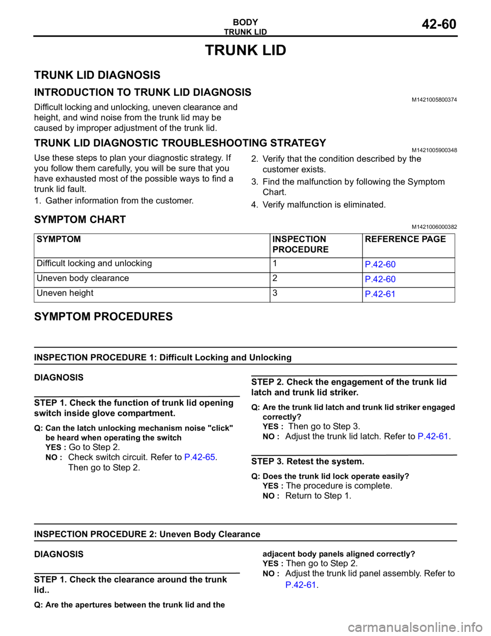
SYMPTOM CHARTM1421006000382
SYMPTOM PROCEDURES
INSPECTION PROCEDURE 1: Difficult Locking and Unlocking
DIAGNOSIS
STEP 1. Check the function of trunk lid opening
switch inside glove compartment.
Q: Can the latch unlocking mechanism noise "click"
be heard when operating the switch
YES :
Go to Step 2.
NO : Check switch circuit. Refer to P.42-65.
Then go to Step 2.
STEP 2. Check the engagement of the trunk lid
latch and trunk lid striker.
Q: Are the trunk lid latch and trunk lid striker engaged
correctly?
YES :
Then go to Step 3.
NO : Adjust the trunk lid latch. Refer to P.42-61.
STEP 3. Retest the system.
Q: Does the trunk lid lock operate easily?
YES :
The procedure is complete.
NO : Return to Step 1.
INSPECTION PROCEDURE 2: Uneven Body Clearance
DIAGNOSIS
STEP 1. Check the clearance around the trunk
lid..
Q: Are the apertures between the trunk lid and the adjacent body panels aligned correctly?
YES :
Then go to Step 2.
NO : Adjust the trunk lid panel assembly. Refer to
P.42-61. SYMPTOM INSPECTION
PROCEDUREREFERENCE PAGE
Difficult locking and unlocking 1
P.42-60
Uneven body clearance 2
P.42-60
Uneven height 3
P.42-61
Page 1128 of 1500
TRUNK LID
BODY42-61
STEP 2. Retest the system.
Q: Are the clearances between the body panels even?
YES :
The procedure is complete.
NO : Return to Step 1.
INSPECTION PROCEDURE 3: Uneven Height
DIAGNOSIS
STEP 1. Check the trunk lid bumper height.
Q: Is the trunk lid bumper height proper?
YES :
Then go to Step 2.
NO : Adjust the trunk lid bumper. Refer to
P.42-62.
STEP 2. Retest the system.
Q: Are the trunk lid and body height even?
YES :
The procedure is complete.
NO : Return to Step 1.
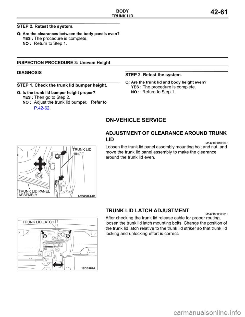
ON-VEHICLE SERVICE
ADJUSTMENT OF CLEARANCE AROUND TRUNK
LID
M1421008100040
Loosen the trunk lid panel assembly mounting bolt and nut, and
move the trunk lid panel assembly to make the clearance
around the trunk lid even.
TRUNK LID LATCH ADJUSTMENTM1421008600012
After checking the trunk lid release cable for proper routing,
loosen the trunk lid latch mounting bolts. Change the position of
the trunk lid latch relative to the trunk lid striker so that trunk lid
locking and unlocking effort is correct.
Page 1129 of 1500
TRUNK LID
BODY42-62
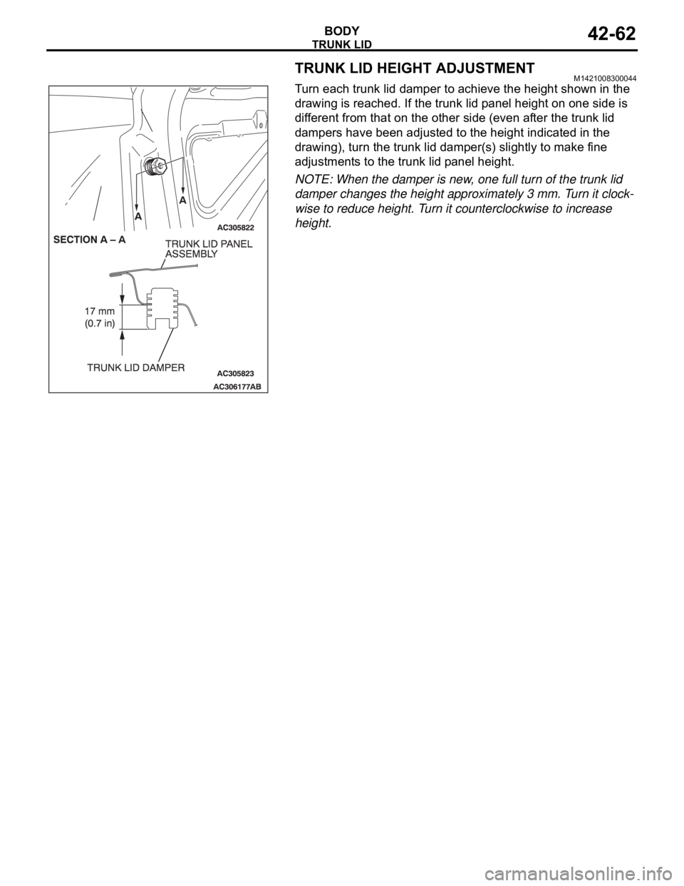
TRUNK LID HEIGHT ADJUSTMENTM1421008300044
Turn each trunk lid damper to achieve the height shown in the
drawing is reached. If the trunk lid panel height on one side is
different from that on the other side (even after the trunk lid
dampers have been adjusted to the height indicated in the
drawing), turn the trunk lid damper(s) slightly to make fine
adjustments to the trunk lid panel height.
NOTE: When the damper is new, one full turn of the trunk lid
damper changes the height approximately 3 mm. Turn it clock-
wise to reduce height. Turn it counterclockwise to increase
height.
Page 1134 of 1500

KEYLESS ENTRY SYSTEM
BODY42-67
KEYLESS ENTRY SYSTEM
GENERAL DESCRIPTIONBGBJABIE
Antenna and receiver are incorporated in the
ETACS-ECU.
ID code can be registered by using Diagnostic
tool (MUT-III).
Transmitter is a key holder type, which incorpo-
rates lock button, unlock button, trunk button and
panic button
When the transmitter unlock button is pressed
once, the driver's door will be unlocked. If the but-
ton is pressed twice, all the doors will be
unlocked. The adjustment function also allows
you to open all the doors by pressing the unlock
button only once. For further details on using the
multi-center display to adjust the unlock opera-
tion, refer to GROUP 54B, On-vehicle Service
P.54B-486.
When the transmitter is operated, the answer-
back function will work as follows:
The answerback operation can be altered as fol-
lows:NOTE: Enabling/disabling the hazard warning
light flashing, the horn sounding in accordance
with the answerback function. For further details
on using the transmitter to adjust answerback,
P.42-72 see the section below. For further details
on using the multi-center display to adjust
answerback, refer to GROUP 54B, On-vehicle
Service P.54B-486. ITEM OPERATION
DOORS LOCKED DOORS UNLOCKED
Dome light Flashes once Illuminates for 15 seconds
Turn-signal lights (RH and LH) Flashes once Flashes twice
Horn Sounds once when the lock button
is pressed with all the doors locked-
ITEM ADJUSTMENT ITEM ADJUSTMENT DETAIL
Keyless entry system
confirmation by turn
signal lightsAdjustment of hazard answerback
when the transmitter is used to
lock doorsWhen adjusting hazard answerback after the
doors are locked with the transmitter, the
following flashing conditions can be selected.
a. Flash (default)
b. No flash
Adjustment of hazard answerback
when the transmitter is used to
unlock doorsWhen adjusting hazard answerback after the
doors are unlocked with the transmitter, the
following flashing conditions can be selected.
a. Flash (default)
b. No flash
Keyless entry system
confirmation by hornAdjustment of horn answerback
when the transmitter is used to
lock doorsWhen adjusting horn answerback after the
doors are locked with the transmitter, the
following horn conditions can be selected.
a. Horn sounds
b. Horn sounds if doors are already locked
(default)
c. Horn does not sound
Page 1138 of 1500

KEYLESS ENTRY SYSTEM
BODY42-71
KEYLESS ENTRY SYSTEM INSPECTIONBGBHCDAE
Check the following items. If defective, refer to GROUP 54B,
SWS Diagnosis P.54B-10).
1. Operate the transmitter to check that the doors can be
locked and unlocked.
NOTE: The adjustment function allows you to change the
unlock operation setting as follows. Prior to that check, con-
firm which setting is activated.
.
a. When the unlock button is pressed once, the driver's
door will be unlocked. Then when the button is pressed
once again, all the doors will be opened (initial setting).
b. When the unlock button is pressed only once, all the
doors will be opened.
2. Press the trunk lid button of transmitter twice (press once,
and then press again within 5 seconds) and confirm that the
trunk lid opens.
3. Operate the transmitter to check that the answerback
function works in response to doors locking/unlocking.
NOTE: The adjustment function allows you to change the
hazard answerback setting as follows. Prior to that check,
confirm which setting is activated.
.
a. Turn-signal lights: Flash once when doors are locked,
and twice when unlocked (initial setting)
b. Turn-signal lights: Flash once when doors are locked,
but does not flash when unlocked.
c. Turn-signal lights: Do not flash when doors are locked,
but flash twice when unlocked.
d. Turn-signal lights: Do not flash when doors are locked
and unlocked.
NOTE: The adjustment function allows you to change the
horn answerback setting as follows. Prior to that check, con-
firm which setting is activated.
.
a. Horn: Sounds once when the lock button is pressed.
b. Horn: Sounds once when the lock button is pressed (ini-
tial setting).
c. Horn: Does not sound.
KEYLESS ENTRY SYSTEM TIMER LOCK
FUNCTION INSPECTION
BGBEBDIA
If the doors are not locked within 30 seconds after the unlock
button is pressed, refer to GROUP 54B, SWS Diagnosis
P.54B-10.
NOTE: If either of the doors is opened or the key is inserted in
the ignition switch within that 30-second period, the timer lock
function will be cancelled.
Page 1154 of 1500

SPECIFICATIONS
BODY42-87
SERVICE SPECIFICATIONSM1421000300299
SEALANT AND ADHESIVESM1421000500204
Door inside handle knob play mm
(in)Front 26.1 - 58.1 (1.028 - 2.287) [Target
value 41 (1.61)]
Rear 30.3 - 58.1 (1.193 - 2.287) [Target
value 41 (1.61)]
Door inside handle lock knob stroke mm (in) 21.6 (0.850)
Door outside handle play mm (in) Front 10
3.5 (0.39 0.138)
Rear 11.2
4 (0.441 0.16)
Power window operation current A 5
1 [Power supply voltage 14.5
0.5V 25
C (77F)]
ITEM STANDARD VALUE
Roof lid glass operation current A 7 or less [at 20
C(68F)]
ITEM SPECIFIED ADHESIVE
Rear window glass 3 M
AAD part No. 8609 super fast urethane and 3 M AAD part No.
8608 super fast urethane primer or equivalent
Windshield
ITEM SPECIFIED SEALANT REMARK
Waterproof film 3 M
AAD Part No. 8633 or equivalent Ribbon sealer
ITEM SPECIFIED ADHESIVE TAPE
Front door opening outer
weatherstripAdhesive tape: Double-sided tape [7 mm (0.28 in) width, 85 mm (3.35
in) length and 0.8 mm (0.03 in) thickness]
Rear door opening outer
weatherstripAdhesive tape: Double-sided tape [7 mm (0.28 in) width, 50 mm (1.97
in) length and 0.8 mm (0.031 in) thickness]
ITEM SPECIFIED SEALANT REMARK
Trunk lid hinge 3 M
AAD part No. 8531 Heavy drip check sealer,
3 M
AAD part No. 8646 Automotive joint and
seam sealer or equivalentBody sealer