2005 MITSUBISHI 380 key battery
[x] Cancel search: key batteryPage 473 of 1500

INPUT SIGNAL PROCEDURES
SIMPLIFIED WIRING SYSTEM (SWS)54B-473
DIAGNOSTIC PROCEDURE
Step 1. Pulse check
Check whether the ETACS-ECU receives signal from a trans-
mitter or not. For this check, you should use the 4-button-type
transmitter (integrated with a key), which has already been reg-
istered.
NOTE: For how to register the keyless entry transmitter
encrypted code, refer to GROUP 42
On-vehicle Service
P.42-73.
OK: The MUT-III sounds or the voltmeter needle fluctu-
ates.
Q: Is the check result normal?
YES : Go to Step 2.
NO : Go to Step 4.
Step 2. Check the transmitter battery.
Refer to GROUP 42
Keyless entry system P.42-70.
Q: Is the check result normal?
YES : Go to Step 3.
NO : Replace the keyless entry key integrated transmitter
battery.
Step 3. Register the encrypted code, and then retest the
system.
(1) Register the keyless entry transmitter again.
(2) Check that each signal is received from the keyless entry
transmitter.
Q: Is the check result normal?
YES : The trouble can be an intermittent malfunction (Refer
to GROUP 00
How to Cope with Intermittent
Malfunction P.00-14).
NO : Replace the keyless entry transmitter.
Step 4. Retest the system.
Check that each signal is received from the keyless entry key
integrated transmitter.
Q: Is the check result normal?
YES : The trouble can be an intermittent malfunction (Refer
to GROUP 00
How to Cope with Intermittent
Malfunction P.00-14).
NO : Replace the ETACS-ECU. System switch Check condition
Keyless entry transmitter
"LOCK/UNLOCK" switchWhen the switch is
turned from off to on
Keyless entry transmitter
"Panic" switchWhen the switch is
turned from off to on
Keyless entry transmitter
"Trunk" switchWhen the switch is
turned from off to on
Page 481 of 1500

CHECK AT ECU TERMINAL
SIMPLIFIED WIRING SYSTEM (SWS)54B-481
22 Output to door unlock (for
driver's door)When driver's door lock actuator
is operating (doors unlocked)Battery positive voltage
23, 24
25 Input of door lock key cylinder
switch (UNLOCK) signalDoor lock key cylinder switch:
UNLOCK0 V
26
28
29 Input of rear door lock actuator
(UNLOCK) signalRear door lock actuator:
UNLOCK0 V
30 Input of key reminder switch
signalKey reminder switch: ON (when
ignition key is removed)0 V
31, 32
33 Input of door lock switch (LOCK)
signalDoor lock switch (incorporated in
power window switch): LOCK0 V
34 Input of door lock switch
(UNLOCK) signalDoor lock switch (incorporated in
power window switch): UNLOCK0 V
35 Input from rear door switch (RH) Rear door switch (RH): ON (rear
door (RH) open)0 V
36 Input of driver's door lock
actuator (UNLOCK) signalDriver's door lock actuator:
UNLOCK0 V
37 Input from trunk lid latch
assemblyTrunk lid latch: ON (trunk open) 0 V
38 Ground (for sensor) Always 0 V
39
41
42 Input of door lock key cylinder
switch (LOCK) signalDoor lock key cylinder switch:
LOCK0 V
43 Input of front passenger's door
lock actuator (UNLOCK) signalFront passenger’s door lock
actuator: UNLOCK0 V
44 Output to horn relay When a horn sounds by the
keyless entry horn answerback
function2 V or less
45 Output to data link connector When DTC sets 0
12 V (pulse signal)
When input check signal is
output0
12 V (when input
pulse signal is
fluctuating)
46 Output to trunk lamp When trunk lid latch on. 0 V
47
48 Input of fog lamp switch signal Fog lamp switch: ON 0 V
49 Input of hazard warning lamp
switch signalHazard warning lamp switch: ON
(When the switch is depressed)0 V
50 Ground (for sensor) Always 0 V
51 Key Ring Antenna (+) 0 V 0 V
52 Key Ring Antenna (-) 0 V 0 V
53 SWS communication line Always 0
12 V (pulse signal) TERMINAL
NO.INSPECTION ITEM INSPECTION CONDITION NORMAL VALUE
Page 547 of 1500

FRONT SEAT BELT
INTERIOR52A-58
FRONT SEAT BELT
REMOVAL AND INSTALLATIONM1523001300370
SRS: Before removing and installing the seat belts with pre-tensioner, refer to GROUP 52B, Seat
Belt with Pre-tensioner P.52B-250.
NOTE:
*If so equipped
Pre-removal and Post-installation Operation
Turn the ignition key to the LOCK (OFF) position.
Disconnect the negative battery terminal.Post-installation Operation
Adjustment Procedures of Special Function (refer to GROUP
52B, On-Vehicle Service P.52B-250.)
1. EXTENDER SEAT BELT
ASSEMBLY*
OUTER SEAT BELT REMOVAL
STEPS
2. SASH GUIDE COVER
CENTER PILLAR TRIM LOWER
(REFER TO P.52A-11.)
3. OUTER SEAT BELT (REFER TO
GROUP 52B, SEAT BELTS WITH
PRE-TENSIONER P.52B-250.)4. CENTER PILLAR TRIM UPPER
(REFER TO P.52A-11.)
5. ADJUSTABLE SEAT BELT ANCOR
INNER SEAT BELT
6. SEAT BELT SWITCH
CONNECTOR
SHIELD COVER (REFER TO
P.52A-33.)
7. INNER SEAT BELTOUTER SEAT BELT REMOVAL
STEPS (Continued)
Page 590 of 1500

CENTRALISED JUNCTION
CIRCUIT DIAGRAMS90-13
19 Front-ECU (Field
effect transistor for
headlamp: Low)Fuse 10 Red Headlamp (LH) and headlamp (Low:
LH)
20 Front-ECU (Taillamp
relay)7.5 Brown A/C-ECU, A/T selector lever position
illumination lamp, combination meter,
fog lamp switch, headlamp (RH),
glove box lamp, hazard warning lamp
switch, multi-center display unit,
radio, CD player, rear combination
lamp (RH), rheostat and TCL switch
21 7.5 Brown Headlamp (LH), license plate lamp
and rear combination lamp (LH)
22 Battery/Alternator
(Fusible link No.27)15 Blue A/C-ECU, column switch,
combination meter, ETACS-ECU,
front-ECU, key reminder switch, multi-
center display unit, radio, CD player,
and vanity mirror lamp
23 Ignition switch (ACC) 10 Red A/C-ECU, accessory socket relay,
ETACS-ECU, multi-center display
unit, radio, CD player.
24 Battery/Alternator
(Fusible link No.27)15 Blue Fuel pump module
25 Ignition switch (ACC) 30 Green Front-ECU and windshield wiper
motor
26 Battery/Alternator
(Fusible link No.27)Fusible
link20 Light blue Anti-lock braking system(solenoid
valve)
27
Alternator120
Battery, front-ECU, fusible link Nos.1,
2, 3, 4, 5 and 26 and fuse Nos.6, 7, 8,
9, 10, 11, 13, 14, 15, 22 and 24 (in
relay box) NO. POWER SUPPLY
CIRCUITNAME RATED
CAPACITY (A)HOUSING
COLOURLOAD CIRCUIT
Page 1069 of 1500

BODY42-2
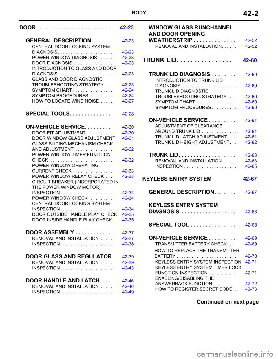
DOOR . . . . . . . . . . . . . . . . . . . . . . . . .42-23
GENERAL DESCRIPTION . . . . . .
42-23
CENTRAL DOOR LOCKING SYSTEM
DIAGNOSIS . . . . . . . . . . . . . . . . . . . . . . 42-23
POWER WINDOW DIAGNOSIS . . . . . . 42-23
DOOR DIAGNOSIS . . . . . . . . . . . . . . . . 42-23
INTRODUCTION TO GLASS AND DOOR
DIAGNOSIS . . . . . . . . . . . . . . . . . . . . . . 42-23
GLASS AND DOOR DIAGNOSTIC
TROUBLESHOOTING STRATEGY . . . 42-23
SYMPTOM CHART . . . . . . . . . . . . . . . . 42-24
SYMPTOM PROCEDURES . . . . . . . . . 42-24
HOW TO LOCATE WIND NOISE . . . . . 42-27
SPECIAL TOOLS. . . . . . . . . . . . . .42-28
ON-VEHICLE SERVICE. . . . . . . . .42-30
DOOR FIT ADJUSTMENT. . . . . . . . . . . 42-30
DOOR WINDOW GLASS ADJUSTMENT42-31
GLASS SLIDING MECHANISM CHECK
AND ADJUSTMENT . . . . . . . . . . . . . . . 42-32
POWER WINDOW TIMER FUNCTION
CHECK . . . . . . . . . . . . . . . . . . . . . . . . . 42-32
POWER WINDOW OPERATING
CURRENT CHECK . . . . . . . . . . . . . . . . 42-33
POWER WINDOW RELAY CHECK . . . 42-33
CIRCUIT BREAKER (INCORPORATED IN
THE POWER WINDOW MOTOR)
INSPECTION . . . . . . . . . . . . . . . . . . . . . 42-34
POWER WINDOW CHECK . . . . . . . . . . 42-34
CENTRAL DOOR LOCKING SYSTEM
INSPECTION . . . . . . . . . . . . . . . . . . . . . 42-34
DOOR OUTSIDE HANDLE PLAY CHECK42-35
DOOR INSIDE HANDLE PLAY CHECK 42-35
DOOR ASSEMBLY . . . . . . . . . . . .42-37
REMOVAL AND INSTALLATION . . . . . 42-37
INSPECTION . . . . . . . . . . . . . . . . . . . . . 42-38
DOOR GLASS AND REGULATOR42-39
REMOVAL AND INSTALLATION . . . . . 42-39
INSPECTION . . . . . . . . . . . . . . . . . . . . . 42-43
DOOR HANDLE AND LATCH . . . .42-46
REMOVAL AND INSTALLATION . . . . . 42-46
INSPECTION . . . . . . . . . . . . . . . . . . . . . 42-49
WINDOW GLASS RUNCHANNEL
AND DOOR OPENING
WEATHERSTRIP . . . . . . . . . . . . . .
42-52
REMOVAL AND INSTALLATION . . . . . . 42-52
TRUNK LID. . . . . . . . . . . . . . . . 42-60
TRUNK LID DIAGNOSIS . . . . . . . .
42-60
INTRODUCTION TO TRUNK LID
DIAGNOSIS . . . . . . . . . . . . . . . . . . . . . . 42-60
TRUNK LID DIAGNOSTIC
TROUBLESHOOTING STRATEGY . . . . 42-60
SYMPTOM CHART . . . . . . . . . . . . . . . . 42-60
SYMPTOM PROCEDURES . . . . . . . . . . 42-60
ON-VEHICLE SERVICE . . . . . . . . .42-61
ADJUSTMENT OF CLEARANCE
AROUND TRUNK LID . . . . . . . . . . . . . . 42-61
TRUNK LID LATCH ADJUSTMENT. . . . 42-61
TRUNK LID HEIGHT ADJUSTMENT . . . 42-62
TRUNK LID . . . . . . . . . . . . . . . . . . .42-63
REMOVAL AND INSTALLATION . . . . . . 42-63
INSPECTION . . . . . . . . . . . . . . . . . . . . . 42-65
KEYLESS ENTRY SYSTEM 42-67
GENERAL DESCRIPTION . . . . . . .
42-67
KEYLESS ENTRY SYSTEM
DIAGNOSIS . . . . . . . . . . . . . . . . . .
42-68
SPECIAL TOOL . . . . . . . . . . . . . . .42-68
ON-VEHICLE SERVICE . . . . . . . . .42-69
TRANSMITTER BATTERY CHECK . . . . 42-69
HOW TO REPLACE THE TRANSMITTER
BATTERY . . . . . . . . . . . . . . . . . . . . . . . . 42-70
KEYLESS ENTRY SYSTEM INSPECTION42-71
KEYLESS ENTRY SYSTEM TIMER LOCK
FUNCTION INSPECTION . . . . . . . . . . . 42-71
ENABLING/DISABLING THE
ANSWERBACK FUNCTION . . . . . . . . . 42-72
HOW TO REGISTER SECRET CODE . 42-73
Continued on next page
Page 1118 of 1500

DOOR
BODY42-51
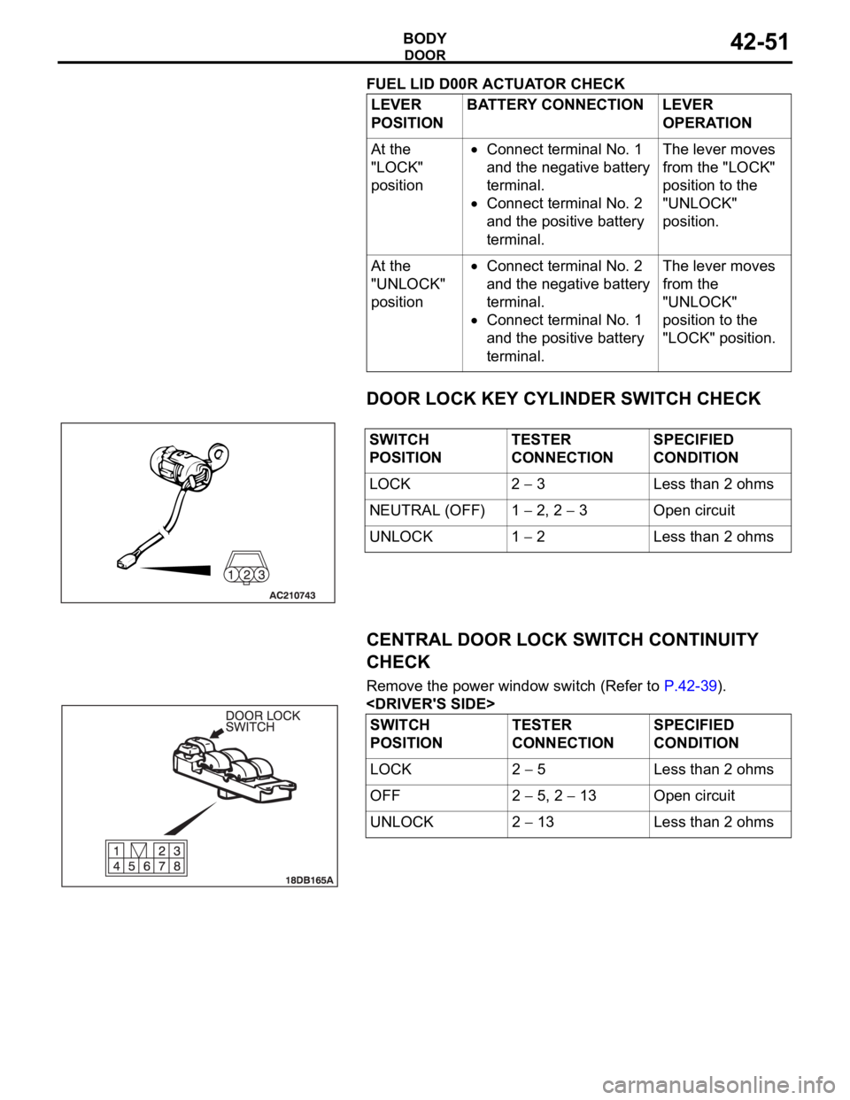
FUEL LID D00R ACTUATOR CHECK
DOOR LOCK KEY CYLINDER SWITCH CHECK
CENTRAL DOOR LOCK SWITCH CONTINUITY
CHECK
Remove the power window switch (Refer to P.42-39).
POSITIONBATTERY CONNECTION LEVER
OPERATION
At the
"LOCK"
position
Connect terminal No. 1
and the negative battery
terminal.
Connect terminal No. 2
and the positive battery
terminal.The lever moves
from the "LOCK"
position to the
"UNLOCK"
position.
At the
"UNLOCK"
position
Connect terminal No. 2
and the negative battery
terminal.
Connect terminal No. 1
and the positive battery
terminal.The lever moves
from the
"UNLOCK"
position to the
"LOCK" position.
SWITCH
POSITIONTESTER
CONNECTIONSPECIFIED
CONDITION
LOCK 2
3 Less than 2 ohms
NEUTRAL (OFF) 1
2, 2 3 Open circuit
UNLOCK 1
2 Less than 2 ohms
SWITCH
POSITIONTESTER
CONNECTIONSPECIFIED
CONDITION
LOCK 2
5 Less than 2 ohms
OFF 2
5, 2 13 Open circuit
UNLOCK 2
13 Less than 2 ohms
Page 1136 of 1500

KEYLESS ENTRY SYSTEM
BODY42-69
ON-VEHICLE SERVICE
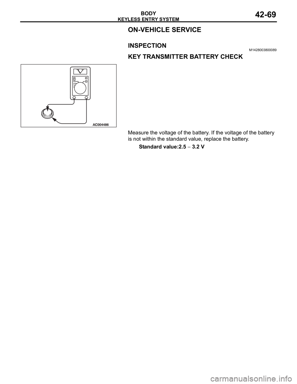
INSPECTIONM1428003800089
KEY TRANSMITTER BATTERY CHECK
Measure the voltage of the battery. If the voltage of the battery
is not within the standard value, replace the battery.
Standard value:2.5
3.2 V
Page 1137 of 1500

KEYLESS ENTRY SYSTEM
BODY42-70
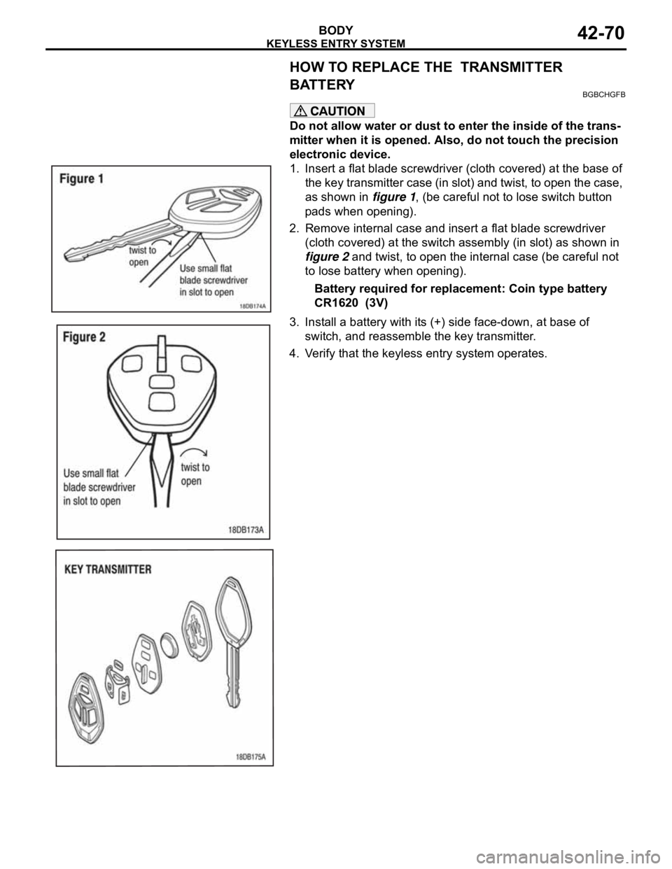
HOW TO REPLACE THE TRANSMITTER
BATTERY
BGBCHGFB
Do not allow water or dust to enter the inside of the trans-
mitter when it is opened. Also, do not touch the precision
electronic device.
1. Insert a flat blade screwdriver (cloth covered) at the base of
the key transmitter case (in slot) and twist, to open the case,
as shown in figure 1, (be careful not to lose switch button
pads when opening).
2. Remove internal case and insert a flat blade screwdriver
(cloth covered) at the switch assembly (in slot) as shown in
figure 2 and twist, to open the internal case (be careful not
to lose battery when opening).
Battery required for replacement: Coin type battery
CR1620 (3V)
3. Install a battery with its (+) side face-down, at base of
switch, and reassemble the key transmitter.
4. Verify that the keyless entry system operates.