2005 MITSUBISHI 380 change time
[x] Cancel search: change timePage 309 of 1500

SYMPTOM PROCEDURES
SIMPLIFIED WIRING SYSTEM (SWS)54B-309
FLASHER TIMER
GENERAL DESCRIPTION CONCERNING THE FLASHER TIMERM1549023600238
Refer to circuit diagrams GROUP-90
Refer to configuration diagrams GROUP-80The following ECUs affect the functions and control
of the flasher timer.
FLASHER TIMER FUNCTION
.
TURN-SIGNAL LAMP
The turn-signal lamp output (flashing signal) is turned ON when
the ignition switch is ON and the turn-signal lamp switch is ON
(LH or RH). If the front turn-signal lamp or rear turn-signal lamp
bulb has burned out, the flashing speed increases to indicate
that the bulb has burned out.
NOTE: If LH or RH side turn signal lamp bulbs have burned
out, the flashing speed will remain the same.
.
TURN-SIGNAL INDICATORS
At the same time that the turn-signal lamps are illuminated, the
ETACS-ECU sends a signal to illuminate the turn-signal lamp
indicator via the CAN bus line. The combination meter receives
the transmitted signal and turns the turn-signal lamp indicator
on and off.
.
HAZARD WARNING LAMP
Detects the signal where the hazard warning lamp switch input
changes from OFF to ON, and reverse the flashing state
according to this signal. The hazard warning lamps toggle on
and off whenever the hazard warning lamp switch is operated.
NOTE: The hazard warning lamp switch is a push-return type
toggle switch. FUNCTION CONTROL ECU
Turn-signal lamp ETACS-ECU, column switch
Turn-signal indicators ETACS-ECU, column switch
Hazard warning lamp ETACS-ECU
Page 402 of 1500

SYMPTOM PROCEDURES
SIMPLIFIED WIRING SYSTEM (SWS)54B-402
INSPECTION PROCEDURE L-1: Can not customise the functions by operating the multi center
display .
NOTE: This troubleshooting procedure requires the
use of diagnostic tool MB991958 and SWS monitor
kit MB991813. For details on how to use the SWS
monitor, refer to "How to connect SWS monitor
P.54B-13."
.
CIRCUIT OPERATION
The ETACS-ECU enables/disables the functions and
changes their operation time, based on the informa-
tion sent from the multi center display
.
TECHNICAL DESCRIPTION (COMMENT)
If it is impossible to customise the functions by oper-
ating the multi center display , connector(s) or wiring
harness in the CAN bus lines, the ETACS-ECU or
the multi center display unit may be defective.
.
TROUBLESHOOTING HINTS
Refer to circuit diagrams GROUP-90
Refer to configuration diagrams GROUP-80
Trouble in input signal system
The wiring harness or connectors may have
loose, corroded, or damaged terminals, or termi-
nals pushed back in the connector
Malfunction of the multi center display
The ETACS-ECU may be defective
.
DIAGNOSIS
Required Special Tools:
MB991223: Harness Set
MB991958: Diagnostic Tool (MUT-III Sub Assembly)
MB991824: Vehicle Communication Interface (V.C.I.)
MB991827: MUT-III USB Cable
MB991910: MUT-III Main Harness A
MB991813: SWS Monitor Kit
MB991806: SWS Monitor Cartridge
MB991812: SWS Monitor Harness (For Column-ECU)
MB991822: Test Probe Harness
Page 769 of 1500

AUTO A/C DIAGNOSIS
HEATER, AIR CONDITIONING AND VENTILATION55-68
SYMPTOM CHART M1552009900495
During diagnosis, a DTC code associated with
other system may be set when the ignition switch
is turned on with connector(s) disconnected. On
completion, confirm all systems for DTC code(s).
If DTC code(s) are set, erase them all.
SYMPTOM INSPECTION
PROCEDUREREFERENCE
PA G E
When the ignition switch is "ON", the A/C does not operate. 1.
P.55-69
When the air outlet changeover control knob is moved to DEFROSTER or
DEFROSTER/FOOT position, the A/C or the inside/outside air
changeover damper motor does not operate.2.
P.55-69
Outside/Inside air changeover is not possible. 3.
P.55-70
When the A/C is operating, temperature inside the passenger
compartment does not decrease (cool air is not emitted).4.
P.55-75
Blower fan and motor do not turn. 5.
P.55-89
Blower air amount cannot be changed. 6.
P.55-100
The A/C indicator flashes. 7.
P.55-104
Defogger function does not operate. 8.
P.55-110
Defogger timer function does not operate. 9.
P.55-121
Malfunction of the A/C-ECU power supply system. 10.
P.55-122
Condenser fan does not operate. 11. REFER TO
GROUP 14
SYMPTOM
CHART P.14-3
When sunlight intensity changes, air outlet temperature does not change. 12
P.55-128
Page 843 of 1500

ON-VEHICLE SERVICE
HEATER, AIR CONDITIONING AND VENTILATION55-142
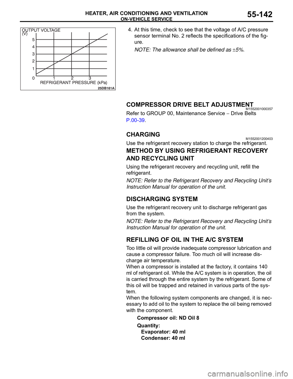
4. At this time, check to see that the voltage of A/C pressure
sensor terminal No. 2 reflects the specifications of the fig-
ure.
NOTE: The allowance shall be defined as
5%.
COMPRESSOR DRIVE BELT ADJUSTMENTM1552001000357
Refer to GROUP 00, Maintenance Service Drive Belts
P.00-39.
CHARGING M1552001200403
Use the refrigerant recovery station to charge the refrigerant.
METHOD BY USING REFRIGERANT RECOVERY
AND RECYCLING UNIT
Using the refrigerant recovery and recycling unit, refill the
refrigerant.
NOTE: Refer to the Refrigerant Recovery and Recycling Unit’s
Instruction Manual for operation of the unit.
DISCHARGING SYSTEM
Use the refrigerant recovery unit to discharge refrigerant gas
from the system.
NOTE: Refer to the Refrigerant Recovery and Recycling Unit’s
Instruction Manual for operation of the unit.
REFILLING OF OIL IN THE A/C SYSTEM
Too little oil will provide inadequate compressor lubrication and
cause a compressor failure. Too much oil will increase dis-
charge air temperature.
When a compressor is installed at the factory, it contains 140
ml of refrigerant oil. While the A/C system is in operation, the oil
is carried through the entire system by the refrigerant. Some of
this oil will be trapped and retained in various parts of the sys-
tem.
When the following system components are changed, it is nec-
essary to add oil to the system to replace the oil being removed
with the component.
Compressor oil: ND Oil 8
Quantity:
Evaporator: 40 ml
Condenser: 40 ml
Page 856 of 1500

HEATER UNIT, HEATER CORE, BLOWER ASSEMBLY AND EVAPORATOR UNIT
HEATER, AIR CONDITIONING AND VENTILATION55-155
INSPECTIONM1552014301157.
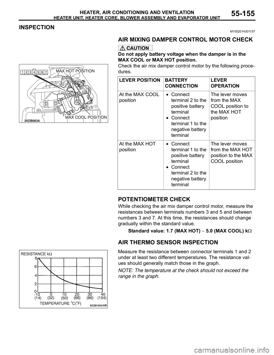
AIR MIXING DAMPER CONTROL MOTOR CHECK
Do not apply battery voltage when the damper is in the
MAX COOL or MAX HOT position.
Check the air mix damper control motor by the following proce-
dures.
.
POTENTIOMETER CHECK
While checking the air mix damper control motor, measure the
resistances between terminals numbers 3 and 5 and between
numbers 3 and 7. At this time, the resistances should change
gradually within the standard value.
Standard value: 1.7 (MAX HOT)
5.0 (MAX COOL) k
AIR THERMO SENSOR INSPECTION
.Measure the resistance between connector terminals 1 and 2
under at least two different temperatures. The resistance val-
ues should generally match those in the graph.
NOTE: The temperature at the check should not exceed the
range in the graph. LEVER POSITION BATTERY
CONNECTIONLEVER
OPERATION
At the MAX COOL
position
Connect
terminal 2 to the
positive battery
terminal
Connect
terminal 1 to the
negative battery
terminalThe lever moves
from the MAX
COOL position to
the MAX HOT
position
At the MAX HOT
position
Connect
terminal 1 to the
positive battery
terminal
Connect
terminal 2 to the
negative battery
terminalThe lever moves
from the MAX HOT
position to the MAX
COOL position
Page 859 of 1500

MOTORS AND TRANSISTOR
HEATER, AIR CONDITIONING AND VENTILATION55-158
INSPECTIONM1551006300338.
MODE SELECTION DAMPER CONTROL MOTOR
CHECK
Do not apply battery voltage when the damper is in the
FACE or DEF position.
Check the mode selection damper control motor by the follow-
ing procedures.
.
POTENTIOMETER CHECK
While checking the mode selection damper control motor, mea-
sure the resistances between terminal numbers 3 and 5 and
between terminal numbers 3 and 7. At this time, the resis-
tances should change gradually within the standard value.
Standard value: 0.8 (DEF)
4.8 (FACE) k
.
OUTSIDE/INSIDE AIR SELECTION DAMPER
CONTROL MOTOR CHECK
Cut off the battery voltage when the damper is in the
inside/outside air position.
Check the outside/inside air selection damper control motor by
the following procedures.LEVER POSITION BATTERY
CONNECTIONLEVER
OPERATION
At the FACE
position
Connect
terminal 2 to the
positive battery
terminal
Connect
terminal 1 to the
negative battery
terminalThe lever moves
from the FACE
position to the DEF
position
At the DEF position
Connect
terminal 1 to the
positive battery
terminal
Connect
terminal 2 to the
negative battery
terminalThe lever moves
from the DEF
position to the
FACE position
Page 907 of 1500

HOW TO DIAGNOSE
GENERAL
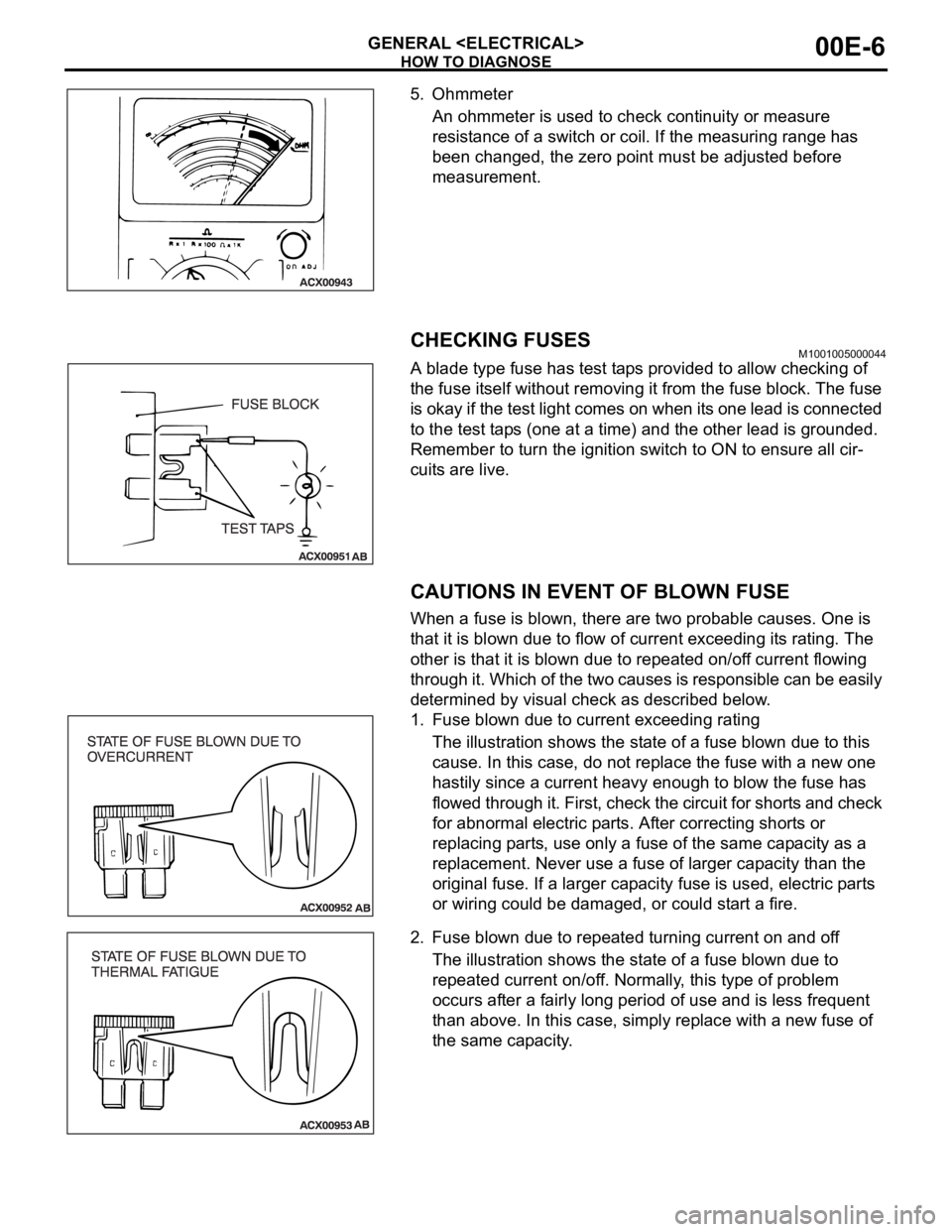
5. Ohmmeter
An ohmmeter is used to check continuity or measure
resistance of a switch or coil. If the measuring range has
been changed, the zero point must be adjusted before
measurement.
CHECKING FUSESM1001005000044
A blade type fuse has test taps provided to allow checking of
the fuse itself without removing it from the fuse block. The fuse
is okay if the test light comes on when its one lead is connected
to the test taps (one at a time) and the other lead is grounded.
Remember to turn the ignition switch to ON to ensure all cir-
cuits are live.
CAUTIONS IN EVENT OF BLOWN FUSE
When a fuse is blown, there are two probable causes. One is
that it is blown due to flow of current exceeding its rating. The
other is that it is blown due to repeated on/off current flowing
through it. Which of the two causes is responsible can be easily
determined by visual check as described below.
1. Fuse blown due to current exceeding rating
The illustration shows the state of a fuse blown due to this
cause. In this case, do not replace the fuse with a new one
hastily since a current heavy enough to blow the fuse has
flowed through it. First, check the circuit for shorts and check
for abnormal electric parts. After correcting shorts or
replacing parts, use only a fuse of the same capacity as a
replacement. Never use a fuse of larger capacity than the
original fuse. If a larger capacity fuse is used, electric parts
or wiring could be damaged, or could start a fire.
2. Fuse blown due to repeated turning current on and off
The illustration shows the state of a fuse blown due to
repeated current on/off. Normally, this type of problem
occurs after a fairly long period of use and is less frequent
than above. In this case, simply replace with a new fuse of
the same capacity.
Page 1047 of 1500

WINDSHIELD WIPER AND WASHER
EXTERIOR51-14
WINDSHIELD WIPER AND WASHER
GENERAL DESCRIPTIONM1511000100558
WINDSHIELD WIPER AND WASHER
OPERATION
.
WINDSHIELD LOW-SPEED (AND
HIGH-SPEED) WIPER OPERATION
If the windshield low-speed wiper switch is turned
to the ON position with the ignition switch at the
"ACC" or "ON" position, the column switch sends
a low-speed wiper ON and high-speed wiper OFF
signals to the front-ECU. This turns the wiper sig-
nal on and the wiper speed control relay off
(low-speed), causing the wipers to operate at
low-speed.
If the windshield high-speed wiper switch is
turned to the ON position, the column switch
sends a low-speed wiper OFF and high-speed
wiper ON signals to the front-ECU. This turns
both the wiper signal and the wiper speed control
relay on (high-speed), causing the wipers to
operate at high-speed.
NOTE: The windshield wiper speed is adjustable
with the built-in wiper speed control relay.
High-speed operations take place when the wiper
speed control relay is set to "ON" and low-speed
operations take place when the wiper speed control
relay is set to "OFF".
.
WINDSHIELD INTERMITTENT WIPER
OPERATION
The ETACS-ECU calculates the wiper operation
interval according to the voltage signal sent from the
column switch. Then the ETACS-ECU sends a signal
to the front-ECU. The front-ECU determines the
wiper operation interval and turns on the wiper relay
signal relay. This causes the wiper auto stop relay to
turn on. Then the wiper auto stop relay will turn off
after the wipers reach the park position. This causes
the wiper signal relay and then the wipers to turn off.
If the wiper signal relay remains off for the wiper
operation interval, the relay turns on again, causing
the wipers to operate in intermittent mode.
.
WINDSHIELD MIST WIPER OPERATION
If the windshield mist wiper switch is turned to the
ON position with the ignition switch at the "ACC"
or "ON" position, the mist wiper high-speed oper-
ation signal is sent to the front-ECU. This signal
turns on the wiper speed control relay, causing
the wipers to work at high-speed while the mist
switch is on.
While the windshield mist wiper switch remains
turned on when the intermittent mode is still work-
ing, the wipers work as the mist wiper. However,
the wipers return to the intermittent mode again
when the switch is changed back to "INT" posi-
tion.
To prevent the windshield mist wiper from operat-
ing when the windshield wiper switch is turned
OFF, the windshield mist wiper does not work for
0.5 second after the windshield intermittent wiper
switch, the windshield low-speed wiper switch
and the windshield high-speed wiper switch are
turned OFF.
.
WINDSHIELD WASHER OPERATION
If the windshield washer switch is turned to the
ON position with the ignition switch at "ACC" or
"ON" position, the windshield washer ON signal is
sent to the front-ECU. After 0.3 second, the wind-
shield wiper signal turns on. After the windshield
washer switch signal turns off, the windshield
wiper signal turns off in three seconds.
If the windshield washer switch is turned on while
the windshield wiper is at intermittent mode, and
the windshield washer switch is turned OFF
within 0.2 second, the wiper works only once to
perform mist operation. When the windshield
washer switch is turned on for more than 0.2 sec-
ond, the wiper performs the same movement as
normal condition from the time when 0.2 second
has elapsed, and then returns to intermittent
operation.
WINDSHIELD WIPER AND WASHER DIAGNOSISM1511000700389
The windshield wiper and washer are controlled by
the Simplified Wiring System (SWS). For trouble-
shooting, refer to GROUP 54B, SWS Diagnosis
P.54B-10.NOTE: Even when the ETACS-ECU has failed, the
windshield wiper can work at low speed as fail-safe
mode. (Normally, the windshield wiper operates
when the ignition switch is at the "ACC" position. But,
if it enters the fail-safe mode, the wiper can operate
only when the ignition switch is at the "ON" position.)