2005 MERCEDES-BENZ SPRINTER turn signal
[x] Cancel search: turn signalPage 705 of 1232
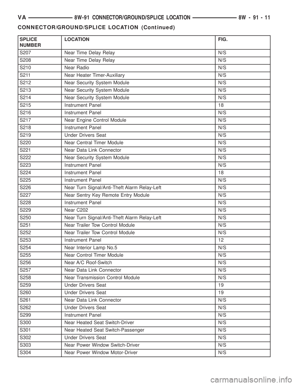
SPLICE
NUMBERLOCATION FIG.
S207 Near Time Delay Relay N/S
S208 Near Time Delay Relay N/S
S210 Near Radio N/S
S211 Near Heater Timer-Auxiliary N/S
S212 Near Security System Module N/S
S213 Near Security System Module N/S
S214 Near Security System Module N/S
S215 Instrument Panel 18
S216 Instrument Panel N/S
S217 Near Engine Control Module N/S
S218 Instrument Panel N/S
S219 Under Drivers Seat N/S
S220 Near Central Timer Module N/S
S221 Near Data Link Connector N/S
S222 Near Security System Module N/S
S223 Instrument Panel N/S
S224 Instrument Panel 18
S225 Instrument Panel N/S
S226 Near Turn Signal/Anti-Theft Alarm Relay-Left N/S
S227 Near Sentry Key Remote Entry Module N/S
S228 Instrument Panel N/S
S229 Near C202 N/S
S250 Near Turn Signal/Anti-Theft Alarm Relay-Left N/S
S251 Near Trailer Tow Control Module N/S
S252 Near Trailer Tow Control Module N/S
S253 Instrument Panel 12
S254 Near Interior Lamp No.5 N/S
S255 Near Control Timer Module N/S
S256 Near A/C Roof-Switch N/S
S257 Near Data Link Connector N/S
S258 Near Transmission Control Module N/S
S259 Under Drivers Seat 19
S260 Under Drivers Seat 19
S261 Near Data Link Connector N/S
S262 Under Drivers Seat N/S
S299 Instrument Panel N/S
S300 Near Heated Seat Switch-Driver N/S
S301 Near Heated Seat Switch-Passenger N/S
S302 Under Drivers Seat N/S
S303 Near Power Window Switch-Driver N/S
S304 Near Power Window Motor-Driver N/S
VA8W-91 CONNECTOR/GROUND/SPLICE LOCATION 8W - 91 - 11
CONNECTOR/GROUND/SPLICE LOCATION (Continued)
Page 844 of 1232
HI PRESSURE FUEL SHUTOFF
SOL
DESCRIPTION
The high pressure fuel injection pump has a inte-
grated shut off valve for one of the high pressure
pump elements. The ECM monitors the fuel temper-
ature and will switch off the element if the fuel tem-
perature reaches above 287ÉF (120C) with the engine
speed above 2200 rpm. The shut off valve is not ser-
viced separately.
OPERATION
The high pressure injection pump element shut off
valve interrupts the fuel high pressure delivery of
one of the injection pump elements in the part load
range. This will reduce the power required for driv-
ing the high pressure pump so as to reduce the fuel
temperature. The pump element is switched off if the
fuel temperature is excessively high forcing it to
return again to the fuel feed to cool. The element
shut off limits the increasing pressure of the injection
pump to ensure that the critical fuel temperature for
the system is not exceeded.
WATER IN FUEL SENSOR
DESCRIPTION
The water in fuel sensor if located in the bottom of
the fuel filter housing. This sensor detects the pres-
ence of water in the fuel. If water is present in the
fuel a signal is sent to the ECM and the ECM signals
the instrument cluster, over the CAN bus, to illumi-
nate the water in fuel warning.
OPERATION
The non-dielectric properties of the water allow the
sensors probes to close the electronic circuit when
water is present in the system. When diesel fuel is
present in the system, it's dielectric (does not conduct
electricity well) properties do not allow any electrical
contact between the probes. A 12V power signal is
always present in order to illuminate the indicator on
the instrument cluster. For removal and installation
procedure refer to (Refer to 14 - FUEL SYSTEM/
FUEL DELIVERY/FUEL FILTER - REMOVAL).
14 - 16 FUEL DELIVERYVA
Page 848 of 1232
CRANKSHAFT POSITION
SENSOR
DESCRIPTION
The crankshaft position sensor is located opposite
the teeth on the flywheel and uses a non contact
method to record the position of the crankshaft. The
leading edges of each tooth on the flywheel generate
a positive signal in the position sensor, while the
trailing edges generate a negative signal. When the
crankshaft is rotating, an alternating voltage is pro-
duced as a result.
The period of the signal is the time required by the
crankshaft to turn through the gap between two fly-
wheel teeth. The clearance between the crankshaft
position sensor and the teeth of the flywheel is fixed
by the installation.
Two teeth on the flywheel are missing. The result-
ing signal gap is used by the ECM to detect the TDC
position of cylinder number one.
OPERATION
The clearance between the crankshaft position sen-
sor and the flywheel are fixed by the installation
position. Two teeth on the flywheel are missing. The
resulting gap is used by the ECM to detect DTC of
cylinder number one. The crankshaft position is cal-
culated to an accuracy of a fraction of a degree so
that the start and end of injection can occur at
exactly the right moment. The engine speed signal is
also processed by the ECM from the crankshaft sen-
sor. This signal is then transferred to other control
modules over the CAN bus.
If the crankshaft position sensor fails, the signal
that provides reference rotation is missing. Injection
may occur at the wrong time and damage the engine.
In this case, the ECM will stop triggering the injec-
tors, the engine would cut out, the engine warning
light would illuminate and the engine will not
restart.
REMOVAL
(1) Disconnect the negative battery cable.
(2) Unplug the crankshaft wiring harness connec-
tor.
(3) Remove the crankshaft sensor retaining bolt
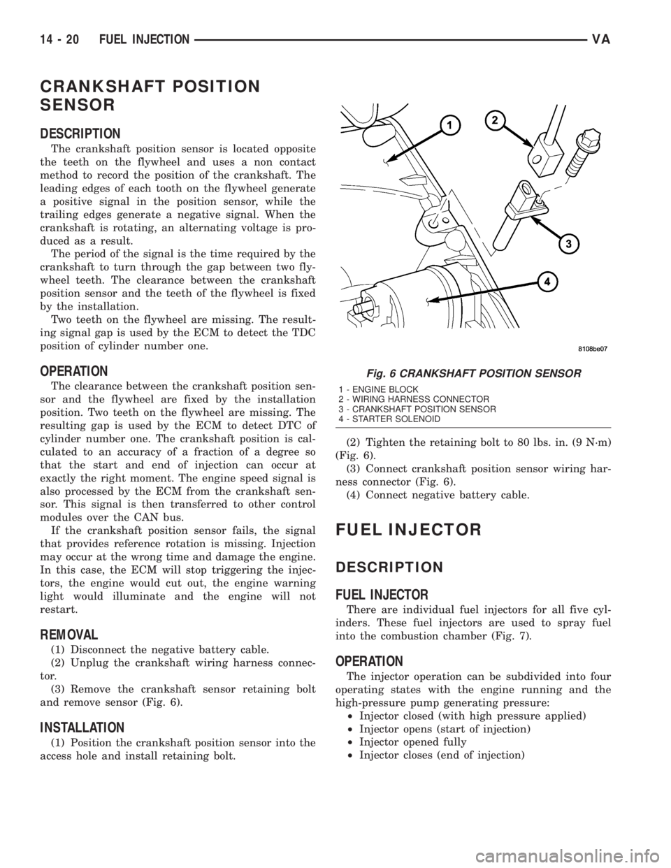
and remove sensor (Fig. 6).
INSTALLATION
(1) Position the crankshaft position sensor into the
access hole and install retaining bolt.(2) Tighten the retaining bolt to 80 lbs. in. (9 N´m)
(Fig. 6).
(3) Connect crankshaft position sensor wiring har-
ness connector (Fig. 6).
(4) Connect negative battery cable.
FUEL INJECTOR
DESCRIPTION
FUEL INJECTOR
There are individual fuel injectors for all five cyl-
inders. These fuel injectors are used to spray fuel
into the combustion chamber (Fig. 7).
OPERATION
The injector operation can be subdivided into four
operating states with the engine running and the
high-pressure pump generating pressure:
²Injector closed (with high pressure applied)
²Injector opens (start of injection)
²Injector opened fully
²Injector closes (end of injection)
Fig. 6 CRANKSHAFT POSITION SENSOR
1 - ENGINE BLOCK
2 - WIRING HARNESS CONNECTOR
3 - CRANKSHAFT POSITION SENSOR
4 - STARTER SOLENOID
14 - 20 FUEL INJECTIONVA
Page 853 of 1232
(15) Install battery tray(Refer to 8 - ELECTRI-
CAL/BATTERY SYSTEM/TRAY - INSTALLATION).
(16) Connect PDC to battery tray.
(17) Install battery (Refer to 8 - ELECTRICAL/
BATTERY SYSTEM/BATTERY - INSTALLATION).
(18) Connect steering coupler at gear box (RHD
Only).
(19) Install turbocharger to right engine mount
bracket (Refer to 11 - EXHAUST SYSTEM/TURBO-
CHARGER SYSTEM - INSTALLATION).
(20) Install charge air cooler to turbocharger inlet
adaptor (Refer to 11 - EXHAUST SYSTEM/CHARGE
AIR COOLER AND PLUMBING - INSTALLATION) .
(21) Install charger air cooler inlet hose (Refer to
11 - EXHAUST SYSTEM/CHARGE AIR COOLER
AND PLUMBING - INSTALLATION).
(22) Install air cleaner box assembly and hoses.
(23) Install upper radiator hose.
(24) Raise vehicle.
(25) Install dipstick tube into oil pan and tighten
retaining bolt.
(26) Install turbocharger down pipe assembly.
(27) Close cooling system drain.
(28) Install lower radiator deflector plate.
(29) Lower vehicle.
(30) Connect negative battery cable.
(31) Install engine cover (Refer to 9 - ENGINE -
INSTALLATION)..
(32) Fill cooling system with the correct mixture to
the proper level (Refer to 7 - COOLING/ENGINE/
COOLANT - STANDARD PROCEDURE).
WARNING: USE EXTREME CAUTION WHEN THE
ENGINE IS OPERATING. DO NOT PUT YOUR
HANDS NEAR PULLEYS, BELTS OR FAN. DO NOT
WEAR LOOSE CLOTHING.
(33) Start engine and inspect for leaks.
(34) Recharge air conditioning system.
FUEL PRESSURE SENSOR
DESCRIPTION
DESCRIPTION
The fuel pressure sensor provides the current low
pressure (the pressure that exist at the inlet of the
high pressure injection pump) fuel pressure to the
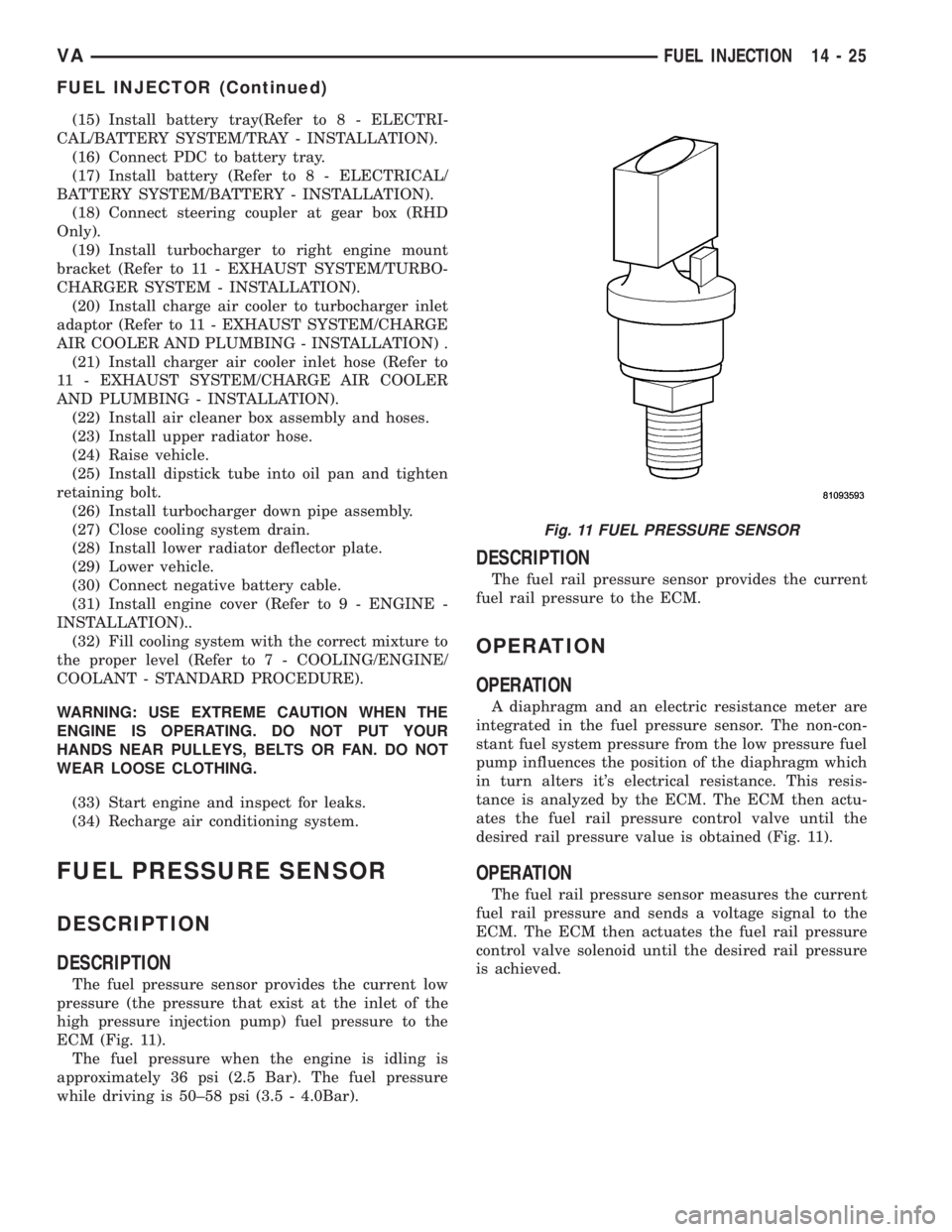
ECM (Fig. 11).
The fuel pressure when the engine is idling is
approximately 36 psi (2.5 Bar). The fuel pressure
while driving is 50±58 psi (3.5 - 4.0Bar).
DESCRIPTION
The fuel rail pressure sensor provides the current
fuel rail pressure to the ECM.
OPERATION
OPERATION
A diaphragm and an electric resistance meter are
integrated in the fuel pressure sensor. The non-con-
stant fuel system pressure from the low pressure fuel
pump influences the position of the diaphragm which
in turn alters it's electrical resistance. This resis-
tance is analyzed by the ECM. The ECM then actu-
ates the fuel rail pressure control valve until the
desired rail pressure value is obtained (Fig. 11).
OPERATION
The fuel rail pressure sensor measures the current
fuel rail pressure and sends a voltage signal to the
ECM. The ECM then actuates the fuel rail pressure
control valve solenoid until the desired rail pressure
is achieved.
Fig. 11 FUEL PRESSURE SENSOR
VAFUEL INJECTION 14 - 25
FUEL INJECTOR (Continued)
Page 855 of 1232
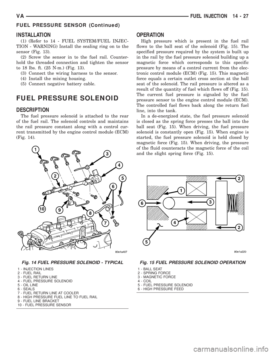
INSTALLATION
(1) (Refer to 14 - FUEL SYSTEM/FUEL INJEC-
TION - WARNING) Install the sealing ring on to the
sensor (Fig. 13).
(2) Screw the sensor in to the fuel rail. Counter-
hold the threaded connection and tighten the sensor
to 18 lbs. ft. (25 N´m.) (Fig. 13).
(3) Connect the wiring harness to the sensor.
(4) Install the mixing housing.
(5) Connect negative battery cable.
FUEL PRESSURE SOLENOID
DESCRIPTION
The fuel pressure solenoid is attached to the rear
of the fuel rail. The solenoid controls and maintains
the rail pressure constant along with a control cur-
rent transmitted by the engine control module (ECM)
(Fig. 14).
OPERATION
High pressure which is present in the fuel rail
flows to the ball seat of the solenoid (Fig. 15). The
specified pressure required by the system is built up
in the rail by the fuel pressure solenoid building up a
magnetic force which corresponds to this specific
pressure by means of a control current from the elec-
tronic control module (ECM) (Fig. 15). This magnetic
force equals a certain outlet cross section at the ball
seat of the solenoid. The rail pressure is altered as a
result of the quantity of fuel which flows off (Fig. 15).
The current fuel pressure is signaled by the fuel
pressure sensor to the engine control module (ECM).
The controlled fuel flows back along the return fuel
line, into the tank.
In a de-energized state, the fuel pressure solenoid
is closed as the spring force presses the ball into the
ball seat (Fig. 15). When driving, the fuel pressure
solenoid is constantly open (Fig. 15). When engine is
started, the fuel pressure solenoid is held closed by
magnetic force (Fig. 15). When driving, the pressure
of the fluid counteracts the magnetic force of the coil
and the slight spring force (Fig. 15).
Fig. 14 FUEL PRESSURE SOLENOID - TYPICAL
1 - INJECTION LINES
2 - FUEL RAIL
3 - FUEL RETURN LINE
4 - FUEL PRESSURE SOLENOID
5 - OIL LINE
6 - SEALS
7 - FUEL RETURN LINE AT COOLER
8 - HIGH PRESSURE FUEL LINE TO FUEL RAIL
9 - FUEL LINE BRACKET
10 - FUEL PRESSURE SENSOR
Fig. 15 FUEL PRESSURE SOLENOID OPERATION
1 - BALL SEAT
2 - SPRING FORCE
3 - MAGNETIC FORCE
4 - COIL
5 - FUEL PRESSURE SOLENOID
6 - HIGH PRESSURE FEED
VAFUEL INJECTION 14 - 27
FUEL PRESSURE SENSOR (Continued)
Page 1030 of 1232
TIRES
DESCRIPTION
DESCRIPTION - TIRES
Tires are designed and engineered for each specific
vehicle. They provide the best overall performance
for normal operation. The ride and handling charac-
teristics match the vehicle's requirements. With
proper care they will give excellent reliability, trac-
tion, skid resistance, and tread life.
Driving habits have more effect on tire life than
any other factor. Careful drivers will obtain in most
cases, much greater mileage than severe use or care-
less drivers. A few of the driving habits which will
shorten the life of any tire are:
²Rapid acceleration
²Severe brake applications
²High speed driving
²Excessive speeds on turns
²Striking curbs and other obstacles
Radial-ply tires are more prone to irregular tread
wear. It is important to follow the tire rotation inter-
val shown in the section on Tire Rotation, (Refer to
22 - TIRES/WHEELS - STANDARD PROCEDURE).
This will help to achieve a greater tread life.
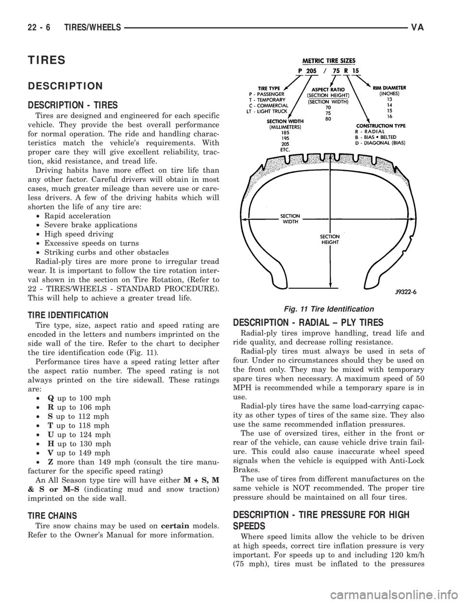
TIRE IDENTIFICATION
Tire type, size, aspect ratio and speed rating are
encoded in the letters and numbers imprinted on the
side wall of the tire. Refer to the chart to decipher
the tire identification code (Fig. 11).
Performance tires have a speed rating letter after
the aspect ratio number. The speed rating is not
always printed on the tire sidewall. These ratings
are:
²Qup to 100 mph
²Rup to 106 mph
²Sup to 112 mph
²Tup to 118 mph
²Uup to 124 mph
²Hup to 130 mph
²Vup to 149 mph
²Zmore than 149 mph (consult the tire manu-
facturer for the specific speed rating)
An All Season type tire will have eitherM+S,M
&SorM±S(indicating mud and snow traction)
imprinted on the side wall.
TIRE CHAINS
Tire snow chains may be used oncertainmodels.
Refer to the Owner's Manual for more information.
DESCRIPTION - RADIAL ± PLY TIRES
Radial-ply tires improve handling, tread life and
ride quality, and decrease rolling resistance.
Radial-ply tires must always be used in sets of
four. Under no circumstances should they be used on
the front only. They may be mixed with temporary
spare tires when necessary. A maximum speed of 50
MPH is recommended while a temporary spare is in
use.
Radial-ply tires have the same load-carrying capac-
ity as other types of tires of the same size. They also
use the same recommended inflation pressures.
The use of oversized tires, either in the front or
rear of the vehicle, can cause vehicle drive train fail-
ure. This could also cause inaccurate wheel speed
signals when the vehicle is equipped with Anti-Lock
Brakes.
The use of tires from different manufactures on the
same vehicle is NOT recommended. The proper tire
pressure should be maintained on all four tires.
DESCRIPTION - TIRE PRESSURE FOR HIGH
SPEEDS
Where speed limits allow the vehicle to be driven
at high speeds, correct tire inflation pressure is very
important. For speeds up to and including 120 km/h
(75 mph), tires must be inflated to the pressures
Fig. 11 Tire Identification
22 - 6 TIRES/WHEELSVA
Page 1141 of 1232
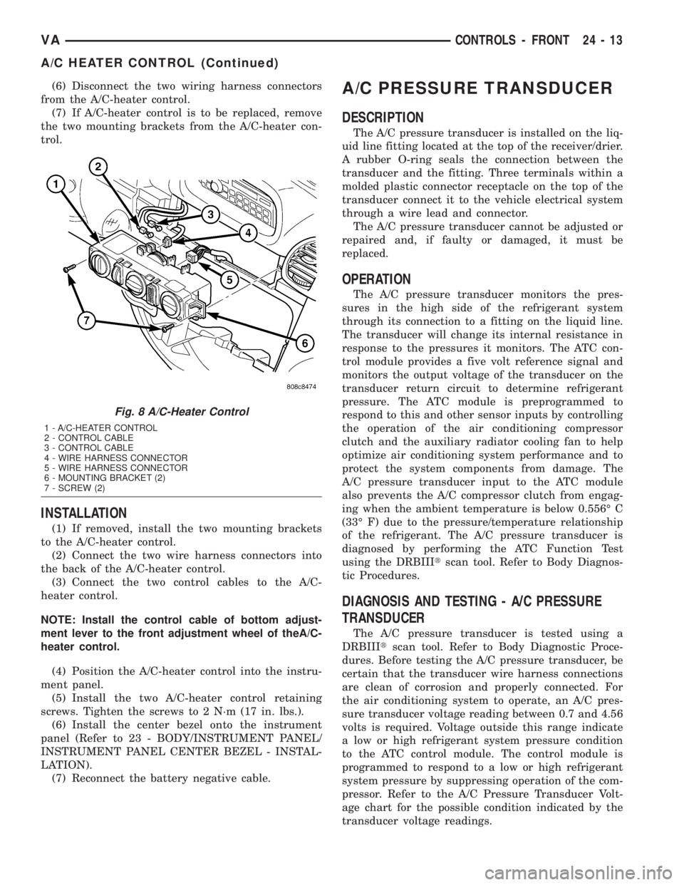
(6) Disconnect the two wiring harness connectors
from the A/C-heater control.
(7) If A/C-heater control is to be replaced, remove
the two mounting brackets from the A/C-heater con-
trol.
INSTALLATION
(1) If removed, install the two mounting brackets
to the A/C-heater control.
(2) Connect the two wire harness connectors into
the back of the A/C-heater control.
(3) Connect the two control cables to the A/C-
heater control.
NOTE: Install the control cable of bottom adjust-
ment lever to the front adjustment wheel of theA/C-
heater control.
(4) Position the A/C-heater control into the instru-
ment panel.
(5) Install the two A/C-heater control retaining
screws. Tighten the screws to 2 N´m (17 in. lbs.).
(6) Install the center bezel onto the instrument
panel (Refer to 23 - BODY/INSTRUMENT PANEL/
INSTRUMENT PANEL CENTER BEZEL - INSTAL-
LATION).
(7) Reconnect the battery negative cable.
A/C PRESSURE TRANSDUCER
DESCRIPTION
The A/C pressure transducer is installed on the liq-
uid line fitting located at the top of the receiver/drier.
A rubber O-ring seals the connection between the
transducer and the fitting. Three terminals within a
molded plastic connector receptacle on the top of the
transducer connect it to the vehicle electrical system
through a wire lead and connector.
The A/C pressure transducer cannot be adjusted or
repaired and, if faulty or damaged, it must be
replaced.
OPERATION
The A/C pressure transducer monitors the pres-
sures in the high side of the refrigerant system
through its connection to a fitting on the liquid line.
The transducer will change its internal resistance in
response to the pressures it monitors. The ATC con-
trol module provides a five volt reference signal and
monitors the output voltage of the transducer on the
transducer return circuit to determine refrigerant
pressure. The ATC module is preprogrammed to
respond to this and other sensor inputs by controlling
the operation of the air conditioning compressor
clutch and the auxiliary radiator cooling fan to help
optimize air conditioning system performance and to
protect the system components from damage. The
A/C pressure transducer input to the ATC module
also prevents the A/C compressor clutch from engag-
ing when the ambient temperature is below 0.556É C
(33É F) due to the pressure/temperature relationship
of the refrigerant. The A/C pressure transducer is
diagnosed by performing the ATC Function Test
using the DRBIIItscan tool. Refer to Body Diagnos-
tic Procedures.
DIAGNOSIS AND TESTING - A/C PRESSURE
TRANSDUCER
The A/C pressure transducer is tested using a
DRBIIItscan tool. Refer to Body Diagnostic Proce-
dures. Before testing the A/C pressure transducer, be
certain that the transducer wire harness connections
are clean of corrosion and properly connected. For
the air conditioning system to operate, an A/C pres-
sure transducer voltage reading between 0.7 and 4.56
volts is required. Voltage outside this range indicate
a low or high refrigerant system pressure condition
to the ATC control module. The control module is
programmed to respond to a low or high refrigerant
system pressure by suppressing operation of the com-
pressor. Refer to the A/C Pressure Transducer Volt-
age chart for the possible condition indicated by the
transducer voltage readings.
Fig. 8 A/C-Heater Control
1 - A/C-HEATER CONTROL
2 - CONTROL CABLE
3 - CONTROL CABLE
4 - WIRE HARNESS CONNECTOR
5 - WIRE HARNESS CONNECTOR
6 - MOUNTING BRACKET (2)
7 - SCREW (2)
VACONTROLS - FRONT 24 - 13
A/C HEATER CONTROL (Continued)
Page 1148 of 1232
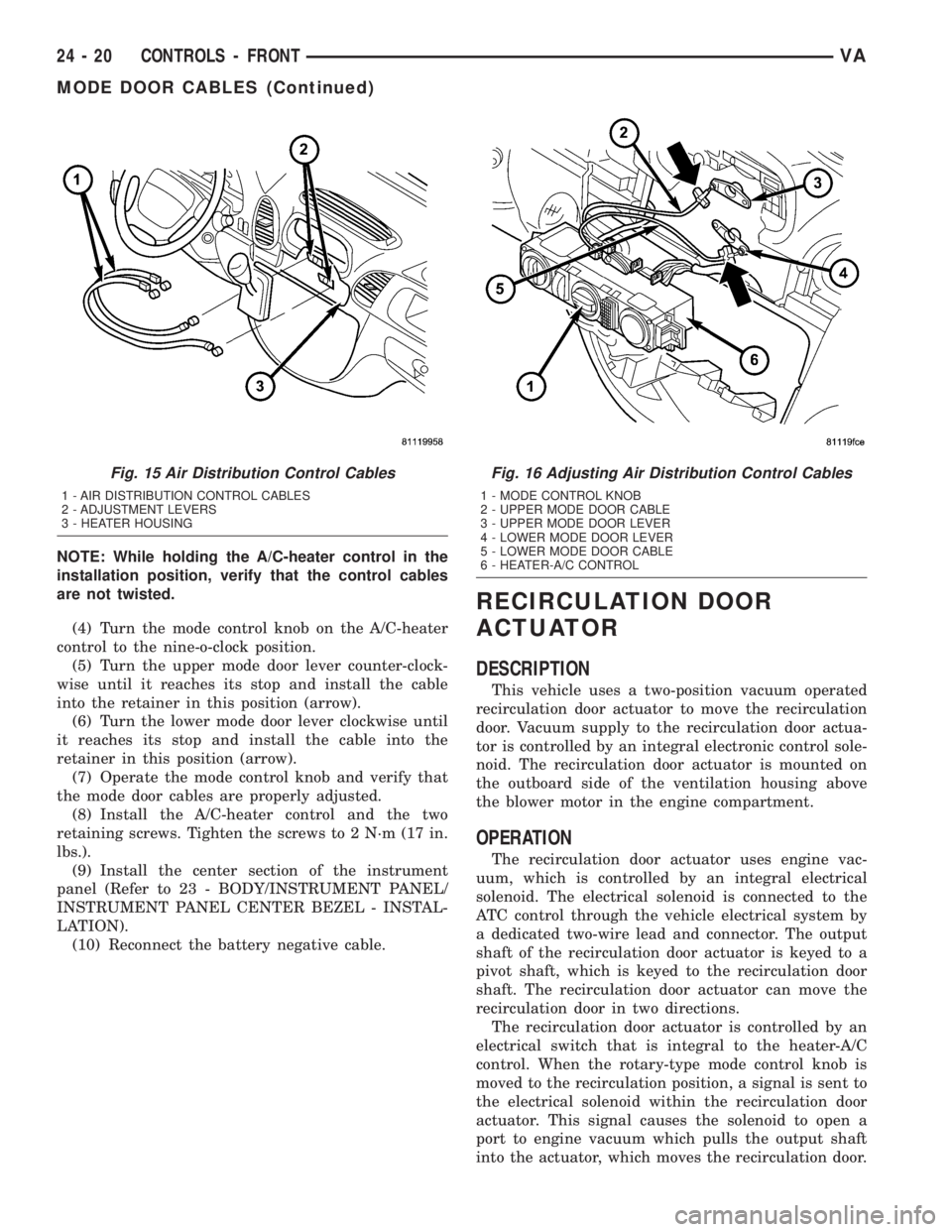
NOTE: While holding the A/C-heater control in the
installation position, verify that the control cables
are not twisted.
(4) Turn the mode control knob on the A/C-heater
control to the nine-o-clock position.
(5) Turn the upper mode door lever counter-clock-
wise until it reaches its stop and install the cable
into the retainer in this position (arrow).
(6) Turn the lower mode door lever clockwise until
it reaches its stop and install the cable into the
retainer in this position (arrow).
(7) Operate the mode control knob and verify that
the mode door cables are properly adjusted.
(8) Install the A/C-heater control and the two
retaining screws. Tighten the screws to 2 N´m (17 in.
lbs.).
(9) Install the center section of the instrument
panel (Refer to 23 - BODY/INSTRUMENT PANEL/
INSTRUMENT PANEL CENTER BEZEL - INSTAL-
LATION).
(10) Reconnect the battery negative cable.
RECIRCULATION DOOR
ACTUATOR
DESCRIPTION
This vehicle uses a two-position vacuum operated
recirculation door actuator to move the recirculation
door. Vacuum supply to the recirculation door actua-
tor is controlled by an integral electronic control sole-
noid. The recirculation door actuator is mounted on
the outboard side of the ventilation housing above
the blower motor in the engine compartment.
OPERATION
The recirculation door actuator uses engine vac-
uum, which is controlled by an integral electrical
solenoid. The electrical solenoid is connected to the
ATC control through the vehicle electrical system by
a dedicated two-wire lead and connector. The output
shaft of the recirculation door actuator is keyed to a
pivot shaft, which is keyed to the recirculation door
shaft. The recirculation door actuator can move the
recirculation door in two directions.
The recirculation door actuator is controlled by an
electrical switch that is integral to the heater-A/C
control. When the rotary-type mode control knob is
moved to the recirculation position, a signal is sent to
the electrical solenoid within the recirculation door
actuator. This signal causes the solenoid to open a
port to engine vacuum which pulls the output shaft
into the actuator, which moves the recirculation door.
Fig. 15 Air Distribution Control Cables
1 - AIR DISTRIBUTION CONTROL CABLES
2 - ADJUSTMENT LEVERS
3 - HEATER HOUSING
Fig. 16 Adjusting Air Distribution Control Cables
1 - MODE CONTROL KNOB
2 - UPPER MODE DOOR CABLE
3 - UPPER MODE DOOR LEVER
4 - LOWER MODE DOOR LEVER
5 - LOWER MODE DOOR CABLE
6 - HEATER-A/C CONTROL
24 - 20 CONTROLS - FRONTVA
MODE DOOR CABLES (Continued)