2005 MERCEDES-BENZ SPRINTER bulb
[x] Cancel search: bulbPage 215 of 1232
INSTALLATION
(1) Position the headlamp leveling switch to the
proper mounting hole on the face of the cluster bezel
(Fig. 29).
(2) Using hand pressure, push the headlamp level-
ing switch firmly and evenly into the switch mount-
ing hole of the cluster bezel until both of the latches
on the switch body are fully engaged.
(3) Reinstall the cluster bezel onto the instrument
panel. (Refer to 23 - BODY/INSTRUMENT PANEL/
CLUSTER BEZEL - INSTALLATION).
(4) Reconnect the battery negative cable.
HIGH BEAM HEADLAMP BULB
REMOVAL
(1) Disconnect and isolate the battery negative
cable.
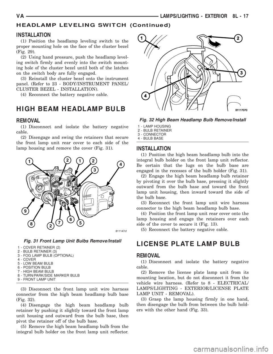
(2) Disengage and swing the retainers that secure
the front lamp unit rear cover to each side of the
lamp housing and remove the cover (Fig. 31).
(3) Disconnect the front lamp unit wire harness
connector from the high beam headlamp bulb base
(Fig. 32).
(4) Disengage the high beam headlamp bulb
retainer by pushing it slightly toward the front lamp
unit housing and outward from the bulb base, then
pivot the retainer off of the bulb base.
(5) Remove the high beam headlamp bulb from the
integral bulb holder on the front lamp unit reflector.
INSTALLATION
(1) Position the high beam headlamp bulb into the
integral bulb holder on the front lamp unit reflector.
Be certain that the lugs on the bulb base are
engaged in the recesses of the bulb holder (Fig. 31).
(2) Engage the high beam headlamp bulb retainer
by pivoting it over the bulb base, pressing it slightly
outward from the bulb base and toward the front
lamp unit housing, then inward toward the side of
the bulb base.
(3) Reconnect the front lamp unit wire harness
connector to the high beam headlamp bulb base.
(4) Position the front lamp unit rear cover onto the
lamp housing and engage the retainers over each
side of the cover to secure it (Fig. 13).
(5) Reconnect the battery negative cable.
LICENSE PLATE LAMP BULB
REMOVAL
(1) Disconnect and isolate the battery negative
cable.
(2) Remove the license plate lamp unit from its
mounting location, but do not disconnect it from the
vehicle wire harness. (Refer to 8 - ELECTRICAL/
LAMPS/LIGHTING - EXTERIOR/LICENSE PLATE
LAMP UNIT - REMOVAL).
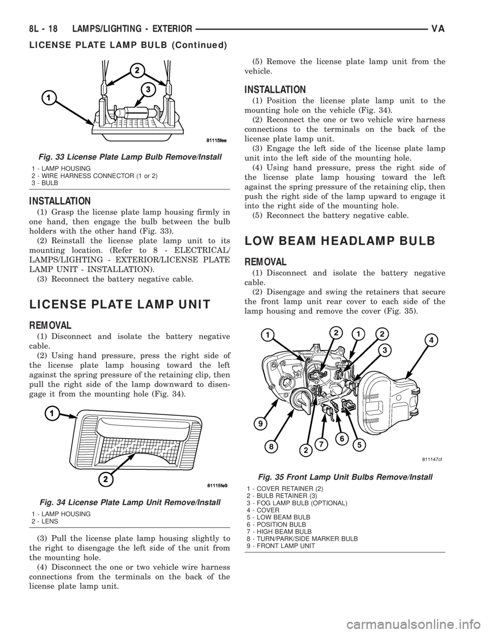
(3) Grasp the lamp housing firmly in one hand,
then disengage the bulb from between the bulb hold-
ers with the other hand (Fig. 33).
Fig. 31 Front Lamp Unit Bulbs Remove/Install
1 - COVER RETAINER (2)
2 - BULB RETAINER (3)
3 - FOG LAMP BULB (OPTIONAL)
4 - COVER
5 - LOW BEAM BULB
6 - POSITION BULB
7 - HIGH BEAM BULB
8 - TURN/PARK/SIDE MARKER BULB
9 - FRONT LAMP UNIT
Fig. 32 High Beam Headlamp Bulb Remove/Install
1 - LAMP HOUSING
2 - BULB RETAINER
3 - CONNECTOR
4 - BULB BASE
VALAMPS/LIGHTING - EXTERIOR 8L - 17
HEADLAMP LEVELING SWITCH (Continued)
Page 216 of 1232
INSTALLATION
(1) Grasp the license plate lamp housing firmly in
one hand, then engage the bulb between the bulb
holders with the other hand (Fig. 33).
(2) Reinstall the license plate lamp unit to its
mounting location. (Refer to 8 - ELECTRICAL/
LAMPS/LIGHTING - EXTERIOR/LICENSE PLATE
LAMP UNIT - INSTALLATION).
(3) Reconnect the battery negative cable.
LICENSE PLATE LAMP UNIT
REMOVAL
(1) Disconnect and isolate the battery negative
cable.
(2) Using hand pressure, press the right side of
the license plate lamp housing toward the left
against the spring pressure of the retaining clip, then
pull the right side of the lamp downward to disen-
gage it from the mounting hole (Fig. 34).
(3) Pull the license plate lamp housing slightly to
the right to disengage the left side of the unit from
the mounting hole.
(4) Disconnect the one or two vehicle wire harness
connections from the terminals on the back of the
license plate lamp unit.(5) Remove the license plate lamp unit from the
vehicle.
INSTALLATION
(1) Position the license plate lamp unit to the
mounting hole on the vehicle (Fig. 34).
(2) Reconnect the one or two vehicle wire harness
connections to the terminals on the back of the
license plate lamp unit.
(3) Engage the left side of the license plate lamp
unit into the left side of the mounting hole.
(4) Using hand pressure, press the right side of
the license plate lamp housing toward the left
against the spring pressure of the retaining clip, then
push the right side of the lamp upward to engage it
into the right side of the mounting hole.
(5) Reconnect the battery negative cable.
LOW BEAM HEADLAMP BULB
REMOVAL
(1) Disconnect and isolate the battery negative
cable.
(2) Disengage and swing the retainers that secure
the front lamp unit rear cover to each side of the
lamp housing and remove the cover (Fig. 35).
Fig. 33 License Plate Lamp Bulb Remove/Install
1 - LAMP HOUSING
2 - WIRE HARNESS CONNECTOR (1 or 2)
3 - BULB
Fig. 34 License Plate Lamp Unit Remove/Install
1 - LAMP HOUSING
2 - LENS
Fig. 35 Front Lamp Unit Bulbs Remove/Install
1 - COVER RETAINER (2)
2 - BULB RETAINER (3)
3 - FOG LAMP BULB (OPTIONAL)
4 - COVER
5 - LOW BEAM BULB
6 - POSITION BULB
7 - HIGH BEAM BULB
8 - TURN/PARK/SIDE MARKER BULB
9 - FRONT LAMP UNIT
8L - 18 LAMPS/LIGHTING - EXTERIORVA
LICENSE PLATE LAMP BULB (Continued)
Page 217 of 1232
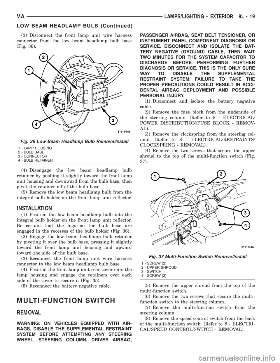
(3) Disconnect the front lamp unit wire harness
connector from the low beam headlamp bulb base
(Fig. 36).
(4) Disengage the low beam headlamp bulb
retainer by pushing it slightly toward the front lamp
unit housing and downward from the bulb base, then
pivot the retainer off of the bulb base.
(5) Remove the low beam headlamp bulb from the
integral bulb holder on the front lamp unit reflector.
INSTALLATION
(1) Position the low beam headlamp bulb into the
integral bulb holder on the front lamp unit reflector.
Be certain that the lugs on the bulb base are
engaged in the recesses of the bulb holder (Fig. 36).
(2) Engage the low beam headlamp bulb retainer
by pivoting it over the bulb base, pressing it slightly
toward the front lamp unit housing and upward
toward the side of the bulb base.
(3) Reconnect the front lamp unit wire harness
connector to the low beam headlamp bulb base.
(4) Position the front lamp unit rear cover onto the
lamp housing and engage the retainers over each
side of the cover to secure it (Fig. 35).
(5) Reconnect the battery negative cable.
MULTI-FUNCTION SWITCH
REMOVAL
WARNING: ON VEHICLES EQUIPPED WITH AIR-
BAGS, DISABLE THE SUPPLEMENTAL RESTRAINT
SYSTEM BEFORE ATTEMPTING ANY STEERING
WHEEL, STEERING COLUMN, DRIVER AIRBAG,PASSENGER AIRBAG, SEAT BELT TENSIONER, OR
INSTRUMENT PANEL COMPONENT DIAGNOSIS OR
SERVICE. DISCONNECT AND ISOLATE THE BAT-
TERY NEGATIVE (GROUND) CABLE, THEN WAIT
TWO MINUTES FOR THE SYSTEM CAPACITOR TO
DISCHARGE BEFORE PERFORMING FURTHER
DIAGNOSIS OR SERVICE. THIS IS THE ONLY SURE
WAY TO DISABLE THE SUPPLEMENTAL
RESTRAINT SYSTEM. FAILURE TO TAKE THE
PROPER PRECAUTIONS COULD RESULT IN ACCI-
DENTAL AIRBAG DEPLOYMENT AND POSSIBLE
PERSONAL INJURY.
(1) Disconnect and isolate the battery negative
cable.
(2) Remove the fuse block from the underside of
the steering column. (Refer to 8 - ELECTRICAL/
POWER DISTRIBUTION/FUSE BLOCK - REMOV-
AL).
(3) Remove the clockspring from the steering col-
umn. (Refer to 8 - ELECTRICAL/RESTRAINTS/
CLOCKSPRING - REMOVAL).
(4) Remove the two screws that secure the upper
shroud to the top of the multi-function switch (Fig.
37).
(5) Remove the upper shroud from the top of the
multi-function switch.
(6) Remove the two screws that secure the multi-
function switch to the steering column.
(7) Remove the multi-function switch from the
steering column.
(8) Remove the speed control switch from the back
of the multi-function switch. (Refer to 8 - ELECTRI-
CAL/SPEED CONTROL/SWITCH - REMOVAL).
Fig. 36 Low Beam Headlamp Bulb Remove/Install
1 - LAMP HOUSING
2 - BULB BASE
3 - CONNECTOR
4 - BULB RETAINER
Fig. 37 Multi-Function Switch Remove/Install
1 - SCREW (2)
2 - UPPER SHROUD
3 - SWITCH
4 - SCREW (2)
VALAMPS/LIGHTING - EXTERIOR 8L - 19
LOW BEAM HEADLAMP BULB (Continued)
Page 219 of 1232
REAR SIDE MARKER LAMP
BULB
REMOVAL
(1) Disconnect and isolate the battery negative
cable.
(2) If the vehicle is so equipped, remove the trim
from the inside of the right or left rear corner pillar.
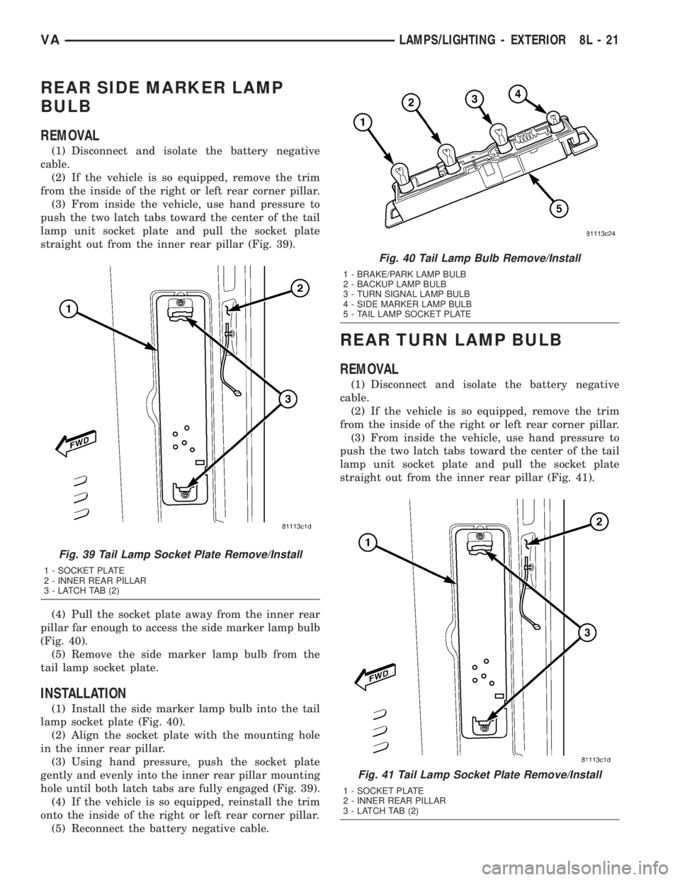
(3) From inside the vehicle, use hand pressure to
push the two latch tabs toward the center of the tail
lamp unit socket plate and pull the socket plate
straight out from the inner rear pillar (Fig. 39).
(4) Pull the socket plate away from the inner rear
pillar far enough to access the side marker lamp bulb
(Fig. 40).
(5) Remove the side marker lamp bulb from the
tail lamp socket plate.
INSTALLATION
(1) Install the side marker lamp bulb into the tail
lamp socket plate (Fig. 40).
(2) Align the socket plate with the mounting hole
in the inner rear pillar.
(3) Using hand pressure, push the socket plate
gently and evenly into the inner rear pillar mounting
hole until both latch tabs are fully engaged (Fig. 39).
(4) If the vehicle is so equipped, reinstall the trim
onto the inside of the right or left rear corner pillar.
(5) Reconnect the battery negative cable.
REAR TURN LAMP BULB
REMOVAL
(1) Disconnect and isolate the battery negative
cable.
(2) If the vehicle is so equipped, remove the trim
from the inside of the right or left rear corner pillar.
(3) From inside the vehicle, use hand pressure to
push the two latch tabs toward the center of the tail
lamp unit socket plate and pull the socket plate
straight out from the inner rear pillar (Fig. 41).
Fig. 39 Tail Lamp Socket Plate Remove/Install
1 - SOCKET PLATE
2 - INNER REAR PILLAR
3 - LATCH TAB (2)
Fig. 40 Tail Lamp Bulb Remove/Install
1 - BRAKE/PARK LAMP BULB
2 - BACKUP LAMP BULB
3 - TURN SIGNAL LAMP BULB
4 - SIDE MARKER LAMP BULB
5 - TAIL LAMP SOCKET PLATE
Fig. 41 Tail Lamp Socket Plate Remove/Install
1 - SOCKET PLATE
2 - INNER REAR PILLAR
3 - LATCH TAB (2)
VALAMPS/LIGHTING - EXTERIOR 8L - 21
Page 220 of 1232
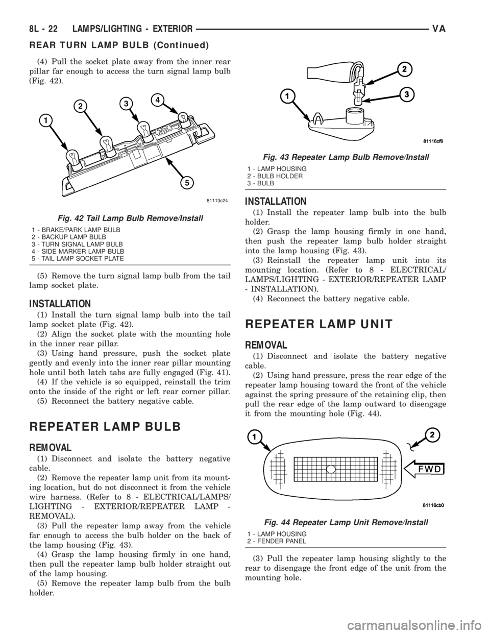
(4) Pull the socket plate away from the inner rear
pillar far enough to access the turn signal lamp bulb
(Fig. 42).
(5) Remove the turn signal lamp bulb from the tail
lamp socket plate.
INSTALLATION
(1) Install the turn signal lamp bulb into the tail
lamp socket plate (Fig. 42).
(2) Align the socket plate with the mounting hole
in the inner rear pillar.
(3) Using hand pressure, push the socket plate
gently and evenly into the inner rear pillar mounting
hole until both latch tabs are fully engaged (Fig. 41).
(4) If the vehicle is so equipped, reinstall the trim
onto the inside of the right or left rear corner pillar.
(5) Reconnect the battery negative cable.
REPEATER LAMP BULB
REMOVAL
(1) Disconnect and isolate the battery negative
cable.
(2) Remove the repeater lamp unit from its mount-
ing location, but do not disconnect it from the vehicle
wire harness. (Refer to 8 - ELECTRICAL/LAMPS/
LIGHTING - EXTERIOR/REPEATER LAMP -
REMOVAL).
(3) Pull the repeater lamp away from the vehicle
far enough to access the bulb holder on the back of
the lamp housing (Fig. 43).
(4) Grasp the lamp housing firmly in one hand,
then pull the repeater lamp bulb holder straight out
of the lamp housing.
(5) Remove the repeater lamp bulb from the bulb
holder.
INSTALLATION
(1) Install the repeater lamp bulb into the bulb
holder.
(2) Grasp the lamp housing firmly in one hand,
then push the repeater lamp bulb holder straight
into the lamp housing (Fig. 43).
(3) Reinstall the repeater lamp unit into its
mounting location. (Refer to 8 - ELECTRICAL/
LAMPS/LIGHTING - EXTERIOR/REPEATER LAMP
- INSTALLATION).
(4) Reconnect the battery negative cable.
REPEATER LAMP UNIT
REMOVAL
(1) Disconnect and isolate the battery negative
cable.
(2) Using hand pressure, press the rear edge of the
repeater lamp housing toward the front of the vehicle
against the spring pressure of the retaining clip, then
pull the rear edge of the lamp outward to disengage
it from the mounting hole (Fig. 44).
(3) Pull the repeater lamp housing slightly to the
rear to disengage the front edge of the unit from the
mounting hole.
Fig. 42 Tail Lamp Bulb Remove/Install
1 - BRAKE/PARK LAMP BULB
2 - BACKUP LAMP BULB
3 - TURN SIGNAL LAMP BULB
4 - SIDE MARKER LAMP BULB
5 - TAIL LAMP SOCKET PLATE
Fig. 43 Repeater Lamp Bulb Remove/Install
1 - LAMP HOUSING
2 - BULB HOLDER
3 - BULB
Fig. 44 Repeater Lamp Unit Remove/Install
1 - LAMP HOUSING
2 - FENDER PANEL
8L - 22 LAMPS/LIGHTING - EXTERIORVA
REAR TURN LAMP BULB (Continued)
Page 221 of 1232
(4) Disconnect the vehicle wire harness connector
from the connector receptacle of the bulb holder on
the back of the repeater lamp unit.
(5) Remove the repeater lamp unit from the vehi-
cle.
INSTALLATION
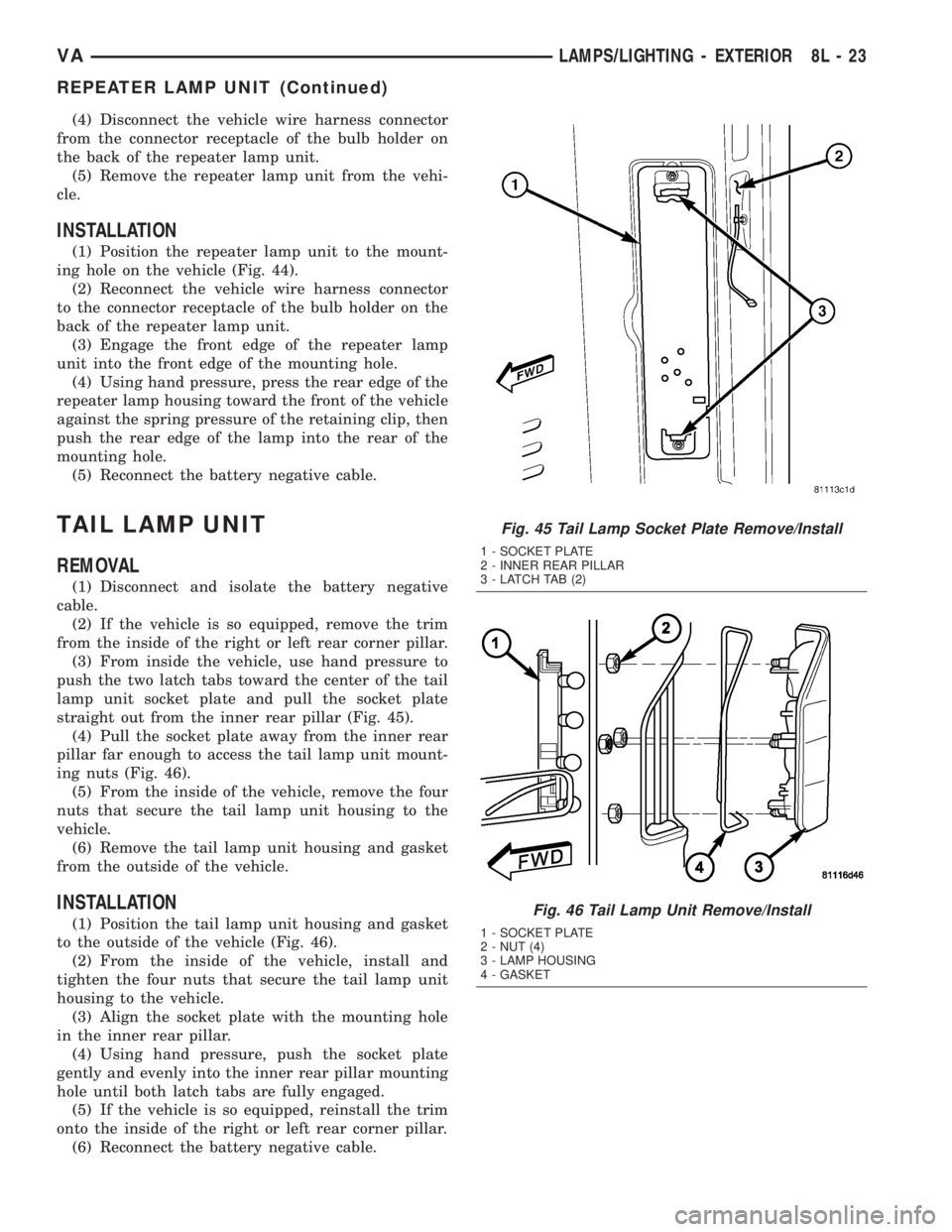
(1) Position the repeater lamp unit to the mount-
ing hole on the vehicle (Fig. 44).
(2) Reconnect the vehicle wire harness connector
to the connector receptacle of the bulb holder on the
back of the repeater lamp unit.
(3) Engage the front edge of the repeater lamp
unit into the front edge of the mounting hole.
(4) Using hand pressure, press the rear edge of the
repeater lamp housing toward the front of the vehicle
against the spring pressure of the retaining clip, then
push the rear edge of the lamp into the rear of the
mounting hole.
(5) Reconnect the battery negative cable.
TAIL LAMP UNIT
REMOVAL
(1) Disconnect and isolate the battery negative
cable.
(2) If the vehicle is so equipped, remove the trim
from the inside of the right or left rear corner pillar.
(3) From inside the vehicle, use hand pressure to
push the two latch tabs toward the center of the tail
lamp unit socket plate and pull the socket plate
straight out from the inner rear pillar (Fig. 45).
(4) Pull the socket plate away from the inner rear
pillar far enough to access the tail lamp unit mount-
ing nuts (Fig. 46).
(5) From the inside of the vehicle, remove the four
nuts that secure the tail lamp unit housing to the
vehicle.
(6) Remove the tail lamp unit housing and gasket
from the outside of the vehicle.
INSTALLATION
(1) Position the tail lamp unit housing and gasket
to the outside of the vehicle (Fig. 46).
(2) From the inside of the vehicle, install and
tighten the four nuts that secure the tail lamp unit
housing to the vehicle.
(3) Align the socket plate with the mounting hole
in the inner rear pillar.
(4) Using hand pressure, push the socket plate
gently and evenly into the inner rear pillar mounting
hole until both latch tabs are fully engaged.
(5) If the vehicle is so equipped, reinstall the trim
onto the inside of the right or left rear corner pillar.
(6) Reconnect the battery negative cable.
Fig. 45 Tail Lamp Socket Plate Remove/Install
1 - SOCKET PLATE
2 - INNER REAR PILLAR
3 - LATCH TAB (2)
Fig. 46 Tail Lamp Unit Remove/Install
1 - SOCKET PLATE
2 - NUT (4)
3 - LAMP HOUSING
4 - GASKET
VALAMPS/LIGHTING - EXTERIOR 8L - 23
REPEATER LAMP UNIT (Continued)
Page 223 of 1232
LAMPS/LIGHTING - INTERIOR
TABLE OF CONTENTS
page page
LAMPS/LIGHTING - INTERIOR
DESCRIPTION.........................25
OPERATION...........................26
SPECIFICATIONS - INTERIOR LIGHTING.....26
ASH RECEIVER/CIGAR LIGHTER LAMP UNIT
REMOVAL.............................27
INSTALLATION.........................27
CARGO/DOME LAMP BULB
REMOVAL.............................27
INSTALLATION.........................27
CARGO/DOME LAMP UNIT
REMOVAL.............................28
INSTALLATION.........................28
CARGO LAMP SWITCH
REMOVAL
REMOVAL - INSTRUMENT PANEL........28
REMOVAL - BULKHEAD................28
REMOVAL - REAR PILLAR..............28
INSTALLATION
INSTALLATION - INSTRUMENT PANEL.....29
INSTALLATION - BULKHEAD.............29
INSTALLATION - REAR PILLAR...........29
DOME/READING LAMP BULB
REMOVAL.............................29INSTALLATION.........................29
DOME/READING LAMP UNIT
REMOVAL.............................30
INSTALLATION.........................30
DOME LAMP/INTRUSION SENSOR BULB
REMOVAL.............................30
INSTALLATION.........................30
DOME LAMP/INTRUSION SENSOR
REMOVAL.............................31
INSTALLATION.........................31
DOOR JAMB SWITCH
REMOVAL.............................31
INSTALLATION.........................31
ENTRY/EXIT LAMP BULB
REMOVAL.............................31
INSTALLATION.........................32
ENTRY/EXIT LAMP UNIT
REMOVAL.............................32
INSTALLATION.........................32
TIME DELAY RELAY
REMOVAL.............................32
INSTALLATION.........................33
LAMPS/LIGHTING - INTERIOR
DESCRIPTION
The interior lighting for this model includes the
following standard and optional incandescent interior
lamps and controls:
²Ash Receiver/Cigar Lighter Lamp- An avail-
able ash receiver/cigar lighter lamp is secured by an
integral mount to the outside of the cigar lighter halo
ring. A single lamp serves to illuminate both the
translucent halo ring and the ash receiver.
²Cargo/Dome Lamp- Several cargo/dome lamp
units located overhead in both the front and rear of
the vehicle interior are standard equipment. These
lamps feature a single incandescent bulb. An optional
version of these lamps includes an integral three-po-
sition switch that protrudes through the lamp lens.
²Cargo Lamp Switch- Toggle-type remote
cargo lamp switches located in the accessory switch
bezel in the center of the instrument panel, on the
back side of the cargo compartment bulkhead panel,
and on the rear cargo door pillar are an available
option on all van models. The instrument panelswitch has two Light-Emitting Diode (LED) units,
one for illumination and a second that provides an
indication. The switches mounted in the cargo com-
partment also have two LED units, but only the indi-
cation LED unit is functional in this application.
²Dome/Reading Lamp- An optional equipment
dome/reading lamp unit is located in the windshield
header area between the driver and passenger sun
visors. This lamp features two incandescent bulbs,
one dome lamp bulb and a second, dedicated reading
lamp bulb. An integral four-position switch protrudes
through the lamp lens.
²Dome Lamp/Intrusion Sensor- An optional
equipment dome lamp/intrusion sensor unit is
located overhead in the vehicle interior. This lamp
features four incandescent bulbs, two for dome lamps
and two for dedicated right and left reading lamps.
This lamp has two integral three-position switches,
one to control interior lamp operation and one to con-
trol reading lamp operation. This lamp also houses
three intrusion sensors that are part of an optional
vehicle theft security system.
²Door Jamb Switch- A door jamb switch for
each front door is standard equipment on all models.
VALAMPS/LIGHTING - INTERIOR 8L - 25
Page 224 of 1232
A door jamb switch for each sliding side door and the
right rear door is standard equipment on wagon mod-
els. The sliding and rear door jamb switches are not
available for van models.
²Entry/Exit Lamp- An entry/exit lamp to illu-
minate each front and sliding side door step well is
optional equipment on wagon models.
²Time Delay Relay- Vehicles equipped with the
optional remote cargo lamp switches also have a time
delay relay located in the electrical center within the
driver side front seat riser.
Hard wired circuitry connects the interior lighting
system components to the electrical system of the
vehicle. These hard wired circuits are integral to sev-
eral wire harnesses, which are routed throughout the
vehicle and retained by many different methods.
These circuits may be connected to each other, to the
vehicle electrical system and to the interior lighting
system components through the use of a combination
of soldered splices, splice block connectors, and many
different types of wire harness terminal connectors
and insulators. Refer to the appropriate wiring infor-
mation. The wiring information includes wiring dia-
grams, proper wire and connector repair procedures,
further details on wire harness routing and reten-
tion, as well as pin-out and location views for the
various wire harness connectors, splices and grounds.
OPERATION
The interior lighting systems can be divided into
two general classifications based upon the circuit
that controls their operation: The interior lighting
circuit, or the exterior lighting circuit. The hard
wired circuits and components of the interior lighting
systems may be diagnosed and tested using conven-
tional diagnostic tools and procedures.
INTERIOR LIGHTING CIRCUIT
Depending upon the vehicle model (van or wagon)
and the selected vehicle options the interior lighting
circuit may include dome/cargo lamps located over-
head in the front and rear of the vehicle, a dome/
reading lamp located in the header area above the
windshield between the sun visors, and entry/exit
lamps located in the front and sliding side door step
wells.
WAGON MODELS
In all wagon models, the lamps in the interior
lighting circuit are provided with battery current at
all times by a fuse in the fuse block beneath the
steering column. The front, side, and rear door jamb
switches control a ground path for each of these
lamps, except for the optional reading lamp. If the
lamp has an optional integral switch, that switch has
three separate positions. The first position provides aground path independent of the door jamb switches
to turn the lamp On. The second, or center position
allows the door jamb switches to control the lamp.
The third position segregates that lamp from the
door jamb switch input, turning the lamp Off. In the
case of the optional dome/reading lamp, the integral
lamp switch has a fourth position which will illumi-
nate only the reading lamp bulb.
VAN MODELS
Unless a van model is equipped with an optional
remote cargo lamp switch, all of the lamps in the
interior lighting circuit operate the same way as the
wagon models except that there are only two door
jamb switches, one for each front door. If the vehicle
is equipped with an optional remote cargo lamp
switch, the lamps in the rear of the vehicle on the
interior lighting circuit are provided with battery
current by the time delay relay. The time delay relay
is a smart relay containing active electronic elements
that comprise an electronic timer logic circuit. When
the remote cargo lamp switches provide the proper
input to the time delay relay, the relay logic responds
by energizing the relay control coil. The energized
relay control coil provides battery current to all of
the lamps on the rear interior lighting circuit and to
the indicator Light-Emitting Diode (LED) units in
the remote cargo switches causing each to illuminate.
If a remote cargo lamp switch remains On for more
than about fifteen minutes, the time delay relay will
then automatically de-energize the rear interior
lighting circuits until the remote cargo lamp switch
is cycled Off and then back On.
EXTERIOR LIGHTING CIRCUIT
The exterior lighting circuit provides battery cur-
rent to the optional ash receiver/cigar lighter lamp
and to the illumination Light-Emitting Diode (LED)
unit within the remote cargo lamp switch in the
instrument panel accessory switch bezel whenever
the exterior lamps are turned On.
SPECIFICATIONS - INTERIOR LIGHTING
BULB SPECIFICATIONS
LAMP BULB
Cargo/Dome Lamp K - 12V 18W
Dome/Reading Lamp K - 12V 10W
Dome Lamp w/Intrusion
SensorK - 12V 6W
Entry/Exit Lamp W5W - 12V 5W
8L - 26 LAMPS/LIGHTING - INTERIORVA
LAMPS/LIGHTING - INTERIOR (Continued)