2005 MERCEDES-BENZ SPRINTER check engine light
[x] Cancel search: check engine lightPage 162 of 1232
OPERATION
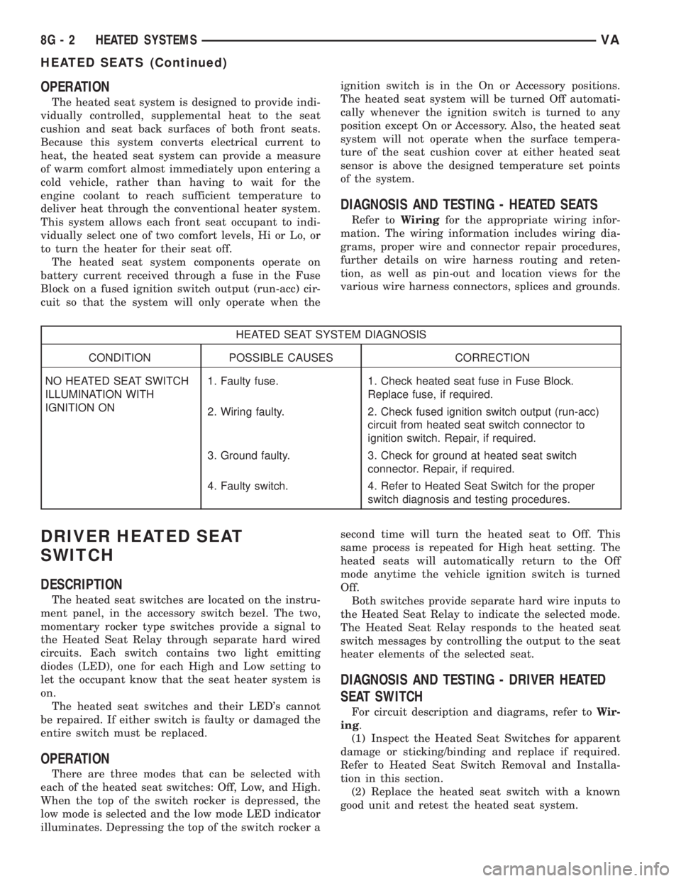
The heated seat system is designed to provide indi-
vidually controlled, supplemental heat to the seat
cushion and seat back surfaces of both front seats.
Because this system converts electrical current to
heat, the heated seat system can provide a measure
of warm comfort almost immediately upon entering a
cold vehicle, rather than having to wait for the
engine coolant to reach sufficient temperature to
deliver heat through the conventional heater system.
This system allows each front seat occupant to indi-
vidually select one of two comfort levels, Hi or Lo, or
to turn the heater for their seat off.
The heated seat system components operate on
battery current received through a fuse in the Fuse
Block on a fused ignition switch output (run-acc) cir-
cuit so that the system will only operate when theignition switch is in the On or Accessory positions.
The heated seat system will be turned Off automati-
cally whenever the ignition switch is turned to any
position except On or Accessory. Also, the heated seat
system will not operate when the surface tempera-
ture of the seat cushion cover at either heated seat
sensor is above the designed temperature set points
of the system.
DIAGNOSIS AND TESTING - HEATED SEATS
Refer toWiringfor the appropriate wiring infor-
mation. The wiring information includes wiring dia-
grams, proper wire and connector repair procedures,
further details on wire harness routing and reten-
tion, as well as pin-out and location views for the
various wire harness connectors, splices and grounds.
HEATED SEAT SYSTEM DIAGNOSIS
CONDITION POSSIBLE CAUSES CORRECTION
NO HEATED SEAT SWITCH
ILLUMINATION WITH
IGNITION ON1. Faulty fuse. 1. Check heated seat fuse in Fuse Block.
Replace fuse, if required.
2. Wiring faulty. 2. Check fused ignition switch output (run-acc)
circuit from heated seat switch connector to
ignition switch. Repair, if required.
3. Ground faulty. 3. Check for ground at heated seat switch
connector. Repair, if required.
4. Faulty switch. 4. Refer to Heated Seat Switch for the proper
switch diagnosis and testing procedures.
DRIVER HEATED SEAT
SWITCH
DESCRIPTION
The heated seat switches are located on the instru-
ment panel, in the accessory switch bezel. The two,
momentary rocker type switches provide a signal to
the Heated Seat Relay through separate hard wired
circuits. Each switch contains two light emitting
diodes (LED), one for each High and Low setting to
let the occupant know that the seat heater system is
on.
The heated seat switches and their LED's cannot
be repaired. If either switch is faulty or damaged the
entire switch must be replaced.
OPERATION
There are three modes that can be selected with
each of the heated seat switches: Off, Low, and High.
When the top of the switch rocker is depressed, the
low mode is selected and the low mode LED indicator
illuminates. Depressing the top of the switch rocker asecond time will turn the heated seat to Off. This
same process is repeated for High heat setting. The
heated seats will automatically return to the Off
mode anytime the vehicle ignition switch is turned
Off.
Both switches provide separate hard wire inputs to
the Heated Seat Relay to indicate the selected mode.
The Heated Seat Relay responds to the heated seat
switch messages by controlling the output to the seat
heater elements of the selected seat.
DIAGNOSIS AND TESTING - DRIVER HEATED
SEAT SWITCH
For circuit description and diagrams, refer toWir-
ing.
(1) Inspect the Heated Seat Switches for apparent
damage or sticking/binding and replace if required.
Refer to Heated Seat Switch Removal and Installa-
tion in this section.
(2) Replace the heated seat switch with a known
good unit and retest the heated seat system.
8G - 2 HEATED SYSTEMSVA
HEATED SEATS (Continued)
Page 210 of 1232
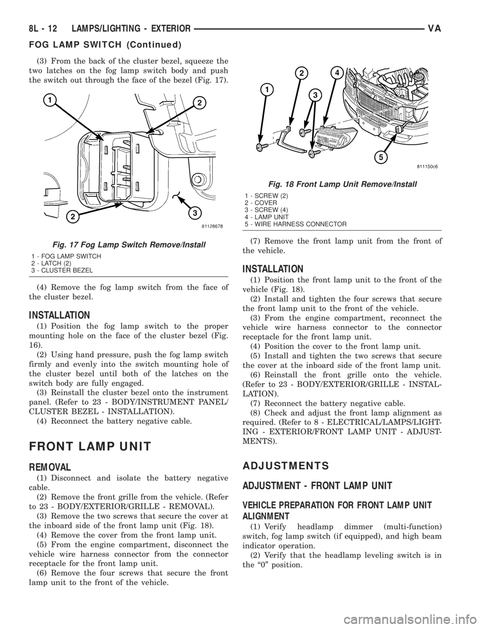
(3) From the back of the cluster bezel, squeeze the
two latches on the fog lamp switch body and push
the switch out through the face of the bezel (Fig. 17).
(4) Remove the fog lamp switch from the face of
the cluster bezel.
INSTALLATION
(1) Position the fog lamp switch to the proper
mounting hole on the face of the cluster bezel (Fig.
16).
(2) Using hand pressure, push the fog lamp switch
firmly and evenly into the switch mounting hole of
the cluster bezel until both of the latches on the
switch body are fully engaged.
(3) Reinstall the cluster bezel onto the instrument
panel. (Refer to 23 - BODY/INSTRUMENT PANEL/
CLUSTER BEZEL - INSTALLATION).
(4) Reconnect the battery negative cable.
FRONT LAMP UNIT
REMOVAL
(1) Disconnect and isolate the battery negative
cable.
(2) Remove the front grille from the vehicle. (Refer
to 23 - BODY/EXTERIOR/GRILLE - REMOVAL).
(3) Remove the two screws that secure the cover at
the inboard side of the front lamp unit (Fig. 18).
(4) Remove the cover from the front lamp unit.
(5) From the engine compartment, disconnect the
vehicle wire harness connector from the connector
receptacle for the front lamp unit.
(6) Remove the four screws that secure the front
lamp unit to the front of the vehicle.(7) Remove the front lamp unit from the front of
the vehicle.
INSTALLATION
(1) Position the front lamp unit to the front of the
vehicle (Fig. 18).
(2) Install and tighten the four screws that secure
the front lamp unit to the front of the vehicle.
(3) From the engine compartment, reconnect the
vehicle wire harness connector to the connector
receptacle for the front lamp unit.
(4) Position the cover to the front lamp unit.
(5) Install and tighten the two screws that secure
the cover at the inboard side of the front lamp unit.
(6) Reinstall the front grille onto the vehicle.
(Refer to 23 - BODY/EXTERIOR/GRILLE - INSTAL-
LATION).
(7) Reconnect the battery negative cable.
(8) Check and adjust the front lamp alignment as
required. (Refer to 8 - ELECTRICAL/LAMPS/LIGHT-
ING - EXTERIOR/FRONT LAMP UNIT - ADJUST-
MENTS).
ADJUSTMENTS
ADJUSTMENT - FRONT LAMP UNIT
VEHICLE PREPARATION FOR FRONT LAMP UNIT
ALIGNMENT
(1) Verify headlamp dimmer (multi-function)
switch, fog lamp switch (if equipped), and high beam
indicator operation.
(2) Verify that the headlamp leveling switch is in
the ª0º position.
Fig. 17 Fog Lamp Switch Remove/Install
1 - FOG LAMP SWITCH
2 - LATCH (2)
3 - CLUSTER BEZEL
Fig. 18 Front Lamp Unit Remove/Install
1 - SCREW (2)
2 - COVER
3 - SCREW (4)
4 - LAMP UNIT
5 - WIRE HARNESS CONNECTOR
8L - 12 LAMPS/LIGHTING - EXTERIORVA
FOG LAMP SWITCH (Continued)
Page 283 of 1232
WIPERS/WASHERS
TABLE OF CONTENTS
page page
WIPERS/WASHERS
DESCRIPTION..........................1
OPERATION............................3
DIAGNOSIS AND TESTING - WIPER &
WASHER SYSTEM.....................5
CLEANING - WIPER & WASHER SYSTEM.....5
INSPECTION - WIPER & WASHER SYSTEM . . . 6
CHECK VALVE
DESCRIPTION..........................7
OPERATION............................7
REMOVAL.............................7
INSTALLATION..........................7
WASHER FLUID LEVEL SWITCH
DESCRIPTION..........................7
OPERATION............................8
WASHER HOSES/TUBES
DESCRIPTION..........................8
OPERATION............................9
WASHER NOZZLE
DESCRIPTION..........................9
OPERATION............................9
REMOVAL.............................9
INSTALLATION..........................9
WASHER PUMP/MOTOR
DESCRIPTION..........................9
OPERATION...........................10
REMOVAL.............................10
INSTALLATION.........................10
WASHER RESERVOIR
DESCRIPTION.........................11OPERATION...........................11
REMOVAL.............................11
INSTALLATION.........................12
WIPER ARM
DESCRIPTION.........................13
OPERATION...........................14
REMOVAL.............................14
INSTALLATION.........................14
WIPER BLADE
DESCRIPTION.........................15
OPERATION...........................15
REMOVAL.............................16
INSTALLATION.........................16
WIPER LINKAGE
DESCRIPTION.........................17
OPERATION...........................17
REMOVAL.............................17
INSTALLATION.........................18
WIPER MOTOR
DESCRIPTION.........................19
OPERATION...........................19
REMOVAL.............................19
INSTALLATION.........................19
WIPER RELAY
DESCRIPTION.........................20
OPERATION...........................21
REMOVAL.............................22
INSTALLATION.........................22
WIPERS/WASHERS
DESCRIPTION
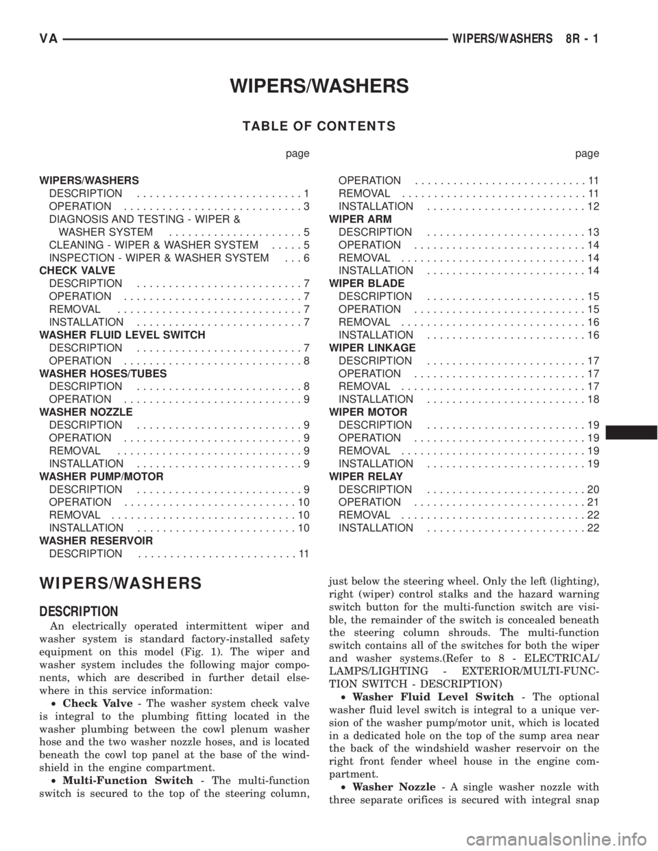
An electrically operated intermittent wiper and
washer system is standard factory-installed safety
equipment on this model (Fig. 1). The wiper and
washer system includes the following major compo-
nents, which are described in further detail else-
where in this service information:
²Check Valve- The washer system check valve
is integral to the plumbing fitting located in the
washer plumbing between the cowl plenum washer
hose and the two washer nozzle hoses, and is located
beneath the cowl top panel at the base of the wind-
shield in the engine compartment.
²Multi-Function Switch- The multi-function
switch is secured to the top of the steering column,just below the steering wheel. Only the left (lighting),
right (wiper) control stalks and the hazard warning
switch button for the multi-function switch are visi-
ble, the remainder of the switch is concealed beneath
the steering column shrouds. The multi-function
switch contains all of the switches for both the wiper
and washer systems.(Refer to 8 - ELECTRICAL/
LAMPS/LIGHTING - EXTERIOR/MULTI-FUNC-
TION SWITCH - DESCRIPTION)
²Washer Fluid Level Switch- The optional
washer fluid level switch is integral to a unique ver-
sion of the washer pump/motor unit, which is located
in a dedicated hole on the top of the sump area near
the back of the windshield washer reservoir on the
right front fender wheel house in the engine com-
partment.
²Washer Nozzle- A single washer nozzle with
three separate orifices is secured with integral snap
VAWIPERS/WASHERS 8R - 1
Page 311 of 1232
TERMINOLOGY
This is a list of terms and definitions used in the
wiring diagrams.
LHD.................Left Hand Drive Vehicles
RHD ...............Right Hand Drive Vehicles
ATX . . Automatic Transmissions-Front Wheel Drive
MTX . . . Manual Transmissions-Front Wheel Drive
AT....Automatic Transmissions-Rear Wheel Drive
MT .....Manual Transmissions-Rear Wheel Drive
SOHC...........Single Over Head Cam Engine
DOHC..........Double Over Head Cam Engine
Built-Up-Export....... Vehicles Built For Sale In
Markets Other Than North America
Except Built-Up-Export . Vehicles Built For Sale In
North America
DESCRIPTION - CIRCUIT INFORMATION
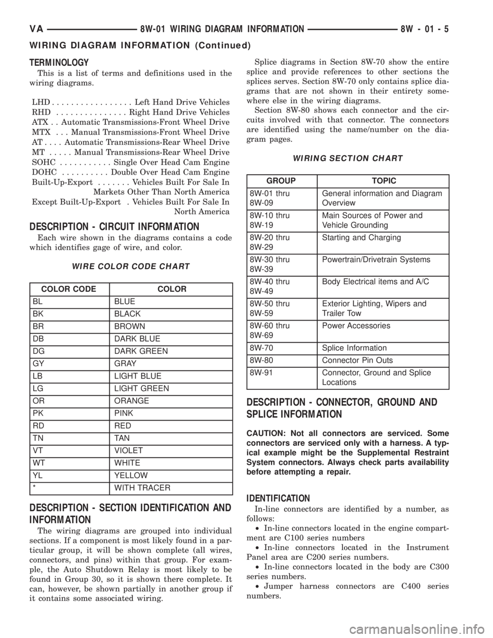
Each wire shown in the diagrams contains a code
which identifies gage of wire, and color.
WIRE COLOR CODE CHART
COLOR CODE COLOR
BL BLUE
BK BLACK
BR BROWN
DB DARK BLUE
DG DARK GREEN
GY GRAY
LB LIGHT BLUE
LG LIGHT GREEN
OR ORANGE
PK PINK
RD RED
TN TAN
VT VIOLET
WT WHITE
YL YELLOW
* WITH TRACER
DESCRIPTION - SECTION IDENTIFICATION AND
INFORMATION
The wiring diagrams are grouped into individual
sections. If a component is most likely found in a par-
ticular group, it will be shown complete (all wires,
connectors, and pins) within that group. For exam-
ple, the Auto Shutdown Relay is most likely to be
found in Group 30, so it is shown there complete. It
can, however, be shown partially in another group if
it contains some associated wiring.Splice diagrams in Section 8W-70 show the entire
splice and provide references to other sections the
splices serves. Section 8W-70 only contains splice dia-
grams that are not shown in their entirety some-
where else in the wiring diagrams.
Section 8W-80 shows each connector and the cir-
cuits involved with that connector. The connectors
are identified using the name/number on the dia-
gram pages.
WIRING SECTION CHART
GROUP TOPIC
8W-01 thru
8W-09General information and Diagram
Overview
8W-10 thru
8W-19Main Sources of Power and
Vehicle Grounding
8W-20 thru
8W-29Starting and Charging
8W-30 thru
8W-39Powertrain/Drivetrain Systems
8W-40 thru
8W-49Body Electrical items and A/C
8W-50 thru
8W-59Exterior Lighting, Wipers and
Trailer Tow
8W-60 thru
8W-69Power Accessories
8W-70 Splice Information
8W-80 Connector Pin Outs
8W-91 Connector, Ground and Splice
Locations
DESCRIPTION - CONNECTOR, GROUND AND
SPLICE INFORMATION
CAUTION: Not all connectors are serviced. Some
connectors are serviced only with a harness. A typ-
ical example might be the Supplemental Restraint
System connectors. Always check parts availability
before attempting a repair.
IDENTIFICATION
In-line connectors are identified by a number, as
follows:
²In-line connectors located in the engine compart-
ment are C100 series numbers
²In-line connectors located in the Instrument
Panel area are C200 series numbers.
²In-line connectors located in the body are C300
series numbers.
²Jumper harness connectors are C400 series
numbers.
VA8W-01 WIRING DIAGRAM INFORMATION 8W - 01 - 5
WIRING DIAGRAM INFORMATION (Continued)
Page 815 of 1232
Low turbocharger boost pressure and low engine
performance can be caused by leaks in the charge air
cooler or it's plumbing. The following procedure out-
lines how to check for leaks in the charge air cooler
system.
(1) Loosen clamp and remove turbocharger to air
inlet duct rubber sleeve from turbocharger.
(2) Insert Special Tool 8442 Adapter into the rub-
ber sleeve. Tighten existing clamp to 8 N´m (72
in.lbs.).
CAUTION: Do not apply more than 138 kpa (20 psi)
air pressure to the charge air cooler system, sever
damage to the charge air cooler system may occur.
(3) Connect regulated air supply to air fitting on
Special Tool 8442 Adapter. Set air pressure to a Max-
imum of 138 kpa (20 psi).
(4) Using soapy water check the air inlet ducts,
rubber sleeves, charge air cooler and intake manifold
for leaks.
REMOVAL
(1) Remove front bumper.
(2) Remove headlamp assemblies.
(3) Remove front cross member together with front
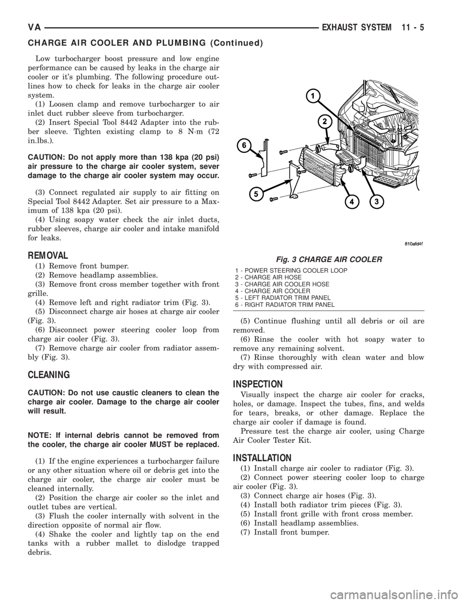
grille.
(4) Remove left and right radiator trim (Fig. 3).
(5) Disconnect charge air hoses at charge air cooler
(Fig. 3).
(6) Disconnect power steering cooler loop from
charge air cooler (Fig. 3).
(7) Remove charge air cooler from radiator assem-
bly (Fig. 3).
CLEANING
CAUTION: Do not use caustic cleaners to clean the
charge air cooler. Damage to the charge air cooler
will result.
NOTE: If internal debris cannot be removed from
the cooler, the charge air cooler MUST be replaced.
(1) If the engine experiences a turbocharger failure
or any other situation where oil or debris get into the
charge air cooler, the charge air cooler must be
cleaned internally.
(2) Position the charge air cooler so the inlet and
outlet tubes are vertical.
(3) Flush the cooler internally with solvent in the
direction opposite of normal air flow.
(4) Shake the cooler and lightly tap on the end
tanks with a rubber mallet to dislodge trapped
debris.(5) Continue flushing until all debris or oil are
removed.
(6) Rinse the cooler with hot soapy water to
remove any remaining solvent.
(7) Rinse thoroughly with clean water and blow
dry with compressed air.
INSPECTION
Visually inspect the charge air cooler for cracks,
holes, or damage. Inspect the tubes, fins, and welds
for tears, breaks, or other damage. Replace the
charge air cooler if damage is found.
Pressure test the charge air cooler, using Charge
Air Cooler Tester Kit.
INSTALLATION
(1) Install charge air cooler to radiator (Fig. 3).
(2) Connect power steering cooler loop to charge
air cooler (Fig. 3).
(3) Connect charge air hoses (Fig. 3).
(4) Install both radiator trim pieces (Fig. 3).
(5) Install front grille with front cross member.
(6) Install headlamp assemblies.
(7) Install front bumper.
Fig. 3 CHARGE AIR COOLER
1 - POWER STEERING COOLER LOOP
2 - CHARGE AIR HOSE
3 - CHARGE AIR COOLER HOSE
4 - CHARGE AIR COOLER
5 - LEFT RADIATOR TRIM PANEL
6 - RIGHT RADIATOR TRIM PANEL
VAEXHAUST SYSTEM 11 - 5
CHARGE AIR COOLER AND PLUMBING (Continued)
Page 874 of 1232
SPECIFICATIONS - TORQUE CHART
TORQUE SPECIFICATIONS
DESCRIPTION N´m Ft. Lbs. In. Lbs.
Power Steering Pump To
Timing Case Cover/
Support21 15 185
High Pressure Flexible
Hose To Power Steering
Pump38 28 336
Power Steering Pulley To
Pump30 22 265
FLUID
STANDARD PROCEDURE
POWER STEERING PUMP FILL AND BLEED
PROCEDURE
(1) Remove the cap from the fluid reservoir.
Check cap seal for damage and replace if
needed.
(2) Fill the power steering pump with Mopar
ATF+4 Automatic Transmission fluid or equivalent.
Do not fill fluid beyond the MAX mark.
(3) Raise the vehicles front wheels off the ground.
(4) With the engine off turn the steering wheel
from right to left.Perform this step until all the
bubble formations can no longer be seen in the
power steering reservoir.
(5) Start the engine and turn the steering wheel
with the engine at idle speed then shut the engine off
and check for correct oil level and no bubble in the
system.
(6) Reinstall power steering cap tightly.
(7) Test the system for leaks and proper operation.
FLUID COOLER TUBE
REMOVAL
(1) Siphon as much power steering fluid as possi-
ble out of the reservoir.
(2) Remove the grille (Refer to 23 - BODY/EXTE-
RIOR/GRILLE - REMOVAL).
(3) Remove the left headlight assembly.
(4) Disconnect the return lines from the cooler
tube.
(5) Remove the radiator clips (2).
(6) Remove the heat shield bolt for the turbo at
the core support.
(7) Remove the right headlight assembly.(8) Remove the core support bolts (4) and discon-
nect the hood latch cable.
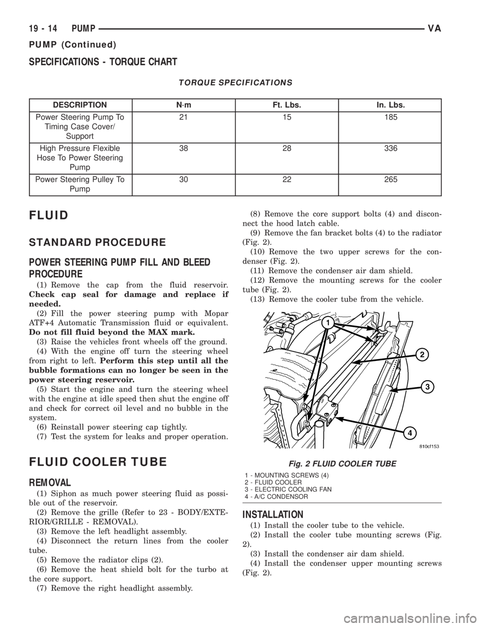
(9) Remove the fan bracket bolts (4) to the radiator
(Fig. 2).
(10) Remove the two upper screws for the con-
denser (Fig. 2).
(11) Remove the condenser air dam shield.
(12) Remove the mounting screws for the cooler
tube (Fig. 2).
(13) Remove the cooler tube from the vehicle.
INSTALLATION
(1) Install the cooler tube to the vehicle.
(2) Install the cooler tube mounting screws (Fig.
2).
(3) Install the condenser air dam shield.
(4) Install the condenser upper mounting screws
(Fig. 2).
Fig. 2 FLUID COOLER TUBE
1 - MOUNTING SCREWS (4)
2 - FLUID COOLER
3 - ELECTRIC COOLING FAN
4 - A/C CONDENSOR
19 - 14 PUMPVA
PUMP (Continued)
Page 1009 of 1232
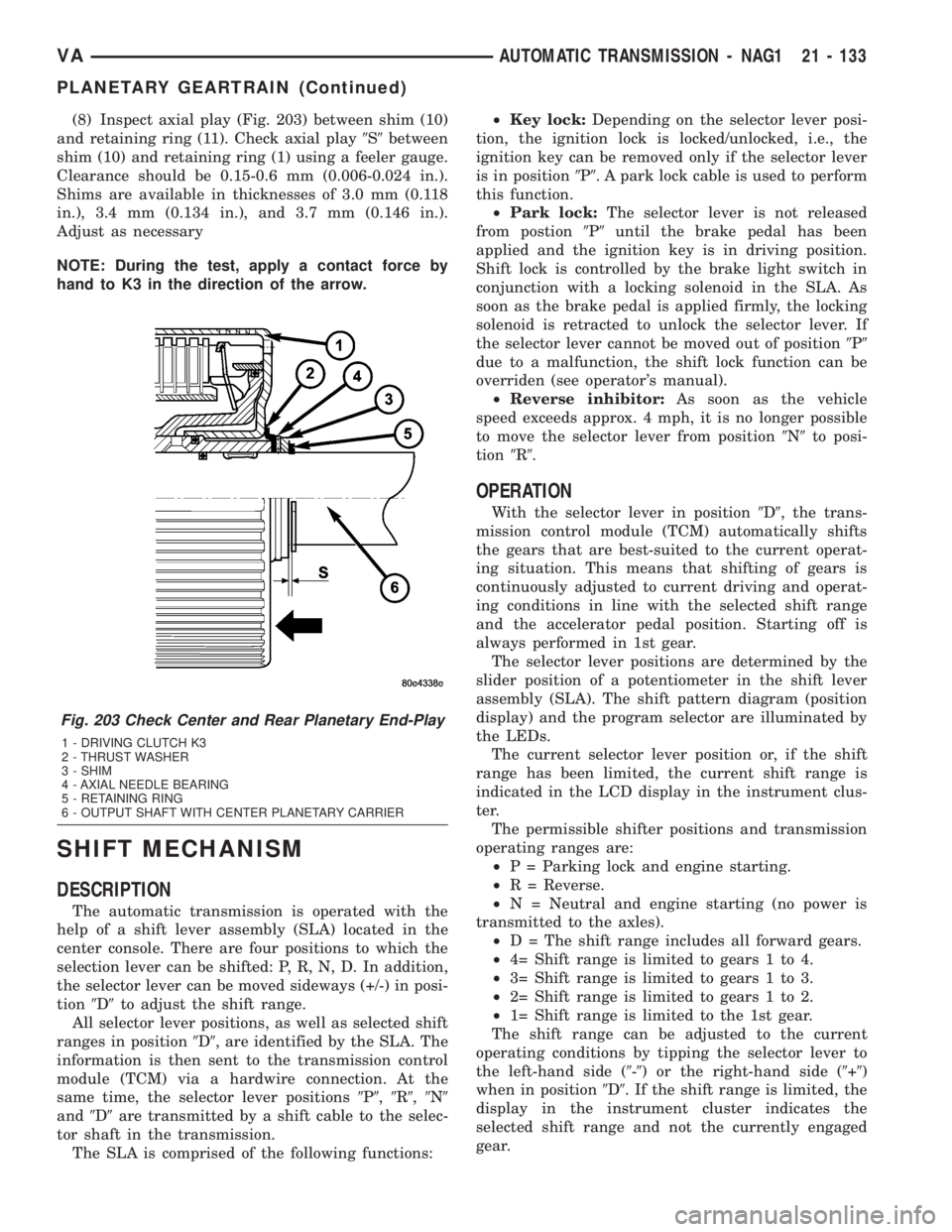
(8) Inspect axial play (Fig. 203) between shim (10)
and retaining ring (11). Check axial play9S9between
shim (10) and retaining ring (1) using a feeler gauge.
Clearance should be 0.15-0.6 mm (0.006-0.024 in.).
Shims are available in thicknesses of 3.0 mm (0.118
in.), 3.4 mm (0.134 in.), and 3.7 mm (0.146 in.).
Adjust as necessary
NOTE: During the test, apply a contact force by
hand to K3 in the direction of the arrow.
SHIFT MECHANISM
DESCRIPTION
The automatic transmission is operated with the
help of a shift lever assembly (SLA) located in the
center console. There are four positions to which the
selection lever can be shifted: P, R, N, D. In addition,
the selector lever can be moved sideways (+/-) in posi-
tion9D9to adjust the shift range.
All selector lever positions, as well as selected shift
ranges in position9D9, are identified by the SLA. The
information is then sent to the transmission control
module (TCM) via a hardwire connection. At the
same time, the selector lever positions9P9,9R9,9N9
and9D9are transmitted by a shift cable to the selec-
tor shaft in the transmission.
The SLA is comprised of the following functions:²Key lock:Depending on the selector lever posi-
tion, the ignition lock is locked/unlocked, i.e., the
ignition key can be removed only if the selector lever
is in position9P9. A park lock cable is used to perform
this function.
²Park lock:The selector lever is not released
from postion9P9until the brake pedal has been
applied and the ignition key is in driving position.
Shift lock is controlled by the brake light switch in
conjunction with a locking solenoid in the SLA. As
soon as the brake pedal is applied firmly, the locking
solenoid is retracted to unlock the selector lever. If
the selector lever cannot be moved out of position9P9
due to a malfunction, the shift lock function can be
overriden (see operator's manual).
²Reverse inhibitor:As soon as the vehicle
speed exceeds approx. 4 mph, it is no longer possible
to move the selector lever from position9N9to posi-
tion9R9.
OPERATION
With the selector lever in position9D9, the trans-
mission control module (TCM) automatically shifts
the gears that are best-suited to the current operat-
ing situation. This means that shifting of gears is
continuously adjusted to current driving and operat-
ing conditions in line with the selected shift range
and the accelerator pedal position. Starting off is
always performed in 1st gear.
The selector lever positions are determined by the
slider position of a potentiometer in the shift lever
assembly (SLA). The shift pattern diagram (position
display) and the program selector are illuminated by
the LEDs.
The current selector lever position or, if the shift
range has been limited, the current shift range is
indicated in the LCD display in the instrument clus-
ter.
The permissible shifter positions and transmission
operating ranges are:
²P = Parking lock and engine starting.
²R = Reverse.
²N = Neutral and engine starting (no power is
transmitted to the axles).
²D = The shift range includes all forward gears.
²4= Shift range is limited to gears 1 to 4.
²3= Shift range is limited to gears 1 to 3.
²2= Shift range is limited to gears 1 to 2.
²1= Shift range is limited to the 1st gear.
The shift range can be adjusted to the current
operating conditions by tipping the selector lever to
the left-hand side (9-9) or the right-hand side (9+9)
when in position9D9. If the shift range is limited, the
display in the instrument cluster indicates the
selected shift range and not the currently engaged
gear.
Fig. 203 Check Center and Rear Planetary End-Play
1 - DRIVING CLUTCH K3
2 - THRUST WASHER
3 - SHIM
4 - AXIAL NEEDLE BEARING
5 - RETAINING RING
6 - OUTPUT SHAFT WITH CENTER PLANETARY CARRIER
VAAUTOMATIC TRANSMISSION - NAG1 21 - 133
PLANETARY GEARTRAIN (Continued)
Page 1022 of 1232
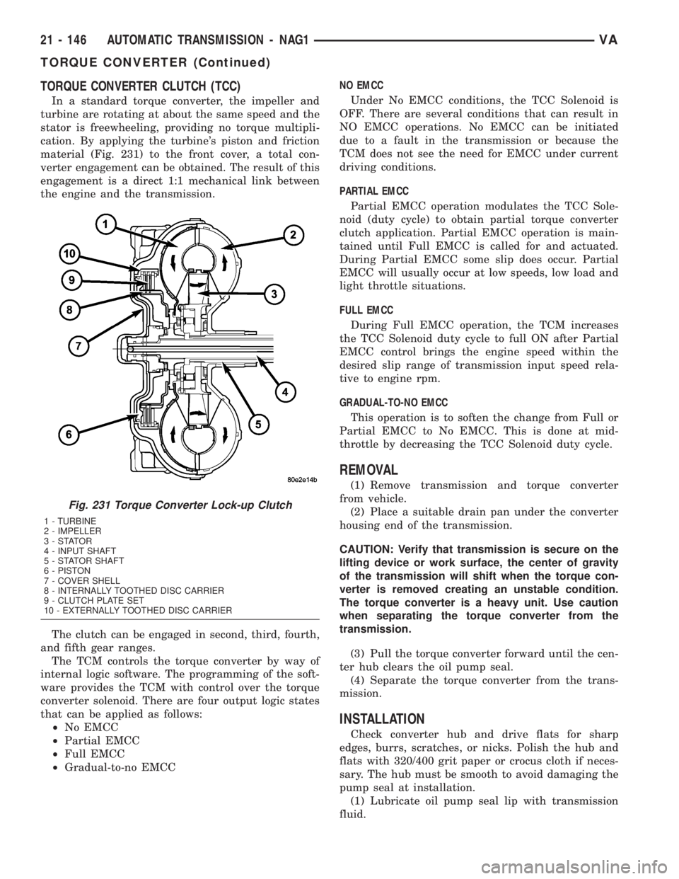
TORQUE CONVERTER CLUTCH (TCC)
In a standard torque converter, the impeller and
turbine are rotating at about the same speed and the
stator is freewheeling, providing no torque multipli-
cation. By applying the turbine's piston and friction
material (Fig. 231) to the front cover, a total con-
verter engagement can be obtained. The result of this
engagement is a direct 1:1 mechanical link between
the engine and the transmission.
The clutch can be engaged in second, third, fourth,
and fifth gear ranges.
The TCM controls the torque converter by way of
internal logic software. The programming of the soft-
ware provides the TCM with control over the torque
converter solenoid. There are four output logic states
that can be applied as follows:
²No EMCC
²Partial EMCC
²Full EMCC
²Gradual-to-no EMCCNO EMCC
Under No EMCC conditions, the TCC Solenoid is
OFF. There are several conditions that can result in
NO EMCC operations. No EMCC can be initiated
due to a fault in the transmission or because the
TCM does not see the need for EMCC under current
driving conditions.
PARTIAL EMCC
Partial EMCC operation modulates the TCC Sole-
noid (duty cycle) to obtain partial torque converter
clutch application. Partial EMCC operation is main-
tained until Full EMCC is called for and actuated.
During Partial EMCC some slip does occur. Partial
EMCC will usually occur at low speeds, low load and
light throttle situations.
FULL EMCC
During Full EMCC operation, the TCM increases
the TCC Solenoid duty cycle to full ON after Partial
EMCC control brings the engine speed within the
desired slip range of transmission input speed rela-
tive to engine rpm.
GRADUAL-TO-NO EMCC
This operation is to soften the change from Full or
Partial EMCC to No EMCC. This is done at mid-
throttle by decreasing the TCC Solenoid duty cycle.
REMOVAL
(1) Remove transmission and torque converter
from vehicle.
(2) Place a suitable drain pan under the converter
housing end of the transmission.
CAUTION: Verify that transmission is secure on the
lifting device or work surface, the center of gravity
of the transmission will shift when the torque con-
verter is removed creating an unstable condition.
The torque converter is a heavy unit. Use caution
when separating the torque converter from the
transmission.
(3) Pull the torque converter forward until the cen-
ter hub clears the oil pump seal.
(4) Separate the torque converter from the trans-
mission.
INSTALLATION
Check converter hub and drive flats for sharp
edges, burrs, scratches, or nicks. Polish the hub and
flats with 320/400 grit paper or crocus cloth if neces-
sary. The hub must be smooth to avoid damaging the
pump seal at installation.
(1) Lubricate oil pump seal lip with transmission
fluid.
Fig. 231 Torque Converter Lock-up Clutch
1 - TURBINE
2 - IMPELLER
3-STATOR
4 - INPUT SHAFT
5 - STATOR SHAFT
6 - PISTON
7 - COVER SHELL
8 - INTERNALLY TOOTHED DISC CARRIER
9 - CLUTCH PLATE SET
10 - EXTERNALLY TOOTHED DISC CARRIER
21 - 146 AUTOMATIC TRANSMISSION - NAG1VA
TORQUE CONVERTER (Continued)