2005 MERCEDES-BENZ SPRINTER relay
[x] Cancel search: relayPage 707 of 1232
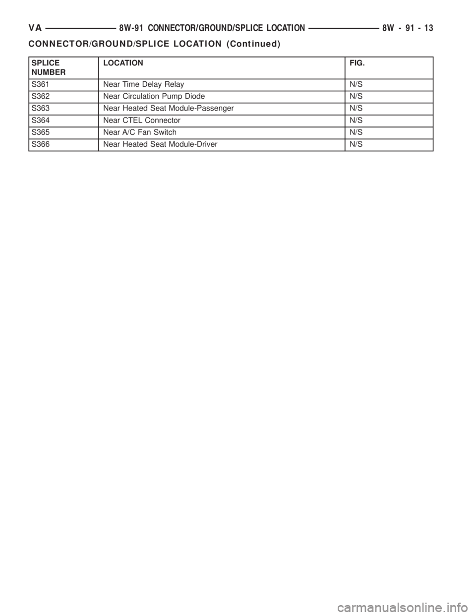
SPLICE
NUMBERLOCATION FIG.
S361 Near Time Delay Relay N/S
S362 Near Circulation Pump Diode N/S
S363 Near Heated Seat Module-Passenger N/S
S364 Near CTEL Connector N/S
S365 Near A/C Fan Switch N/S
S366 Near Heated Seat Module-Driver N/S
VA8W-91 CONNECTOR/GROUND/SPLICE LOCATION 8W - 91 - 13
CONNECTOR/GROUND/SPLICE LOCATION (Continued)
Page 733 of 1232
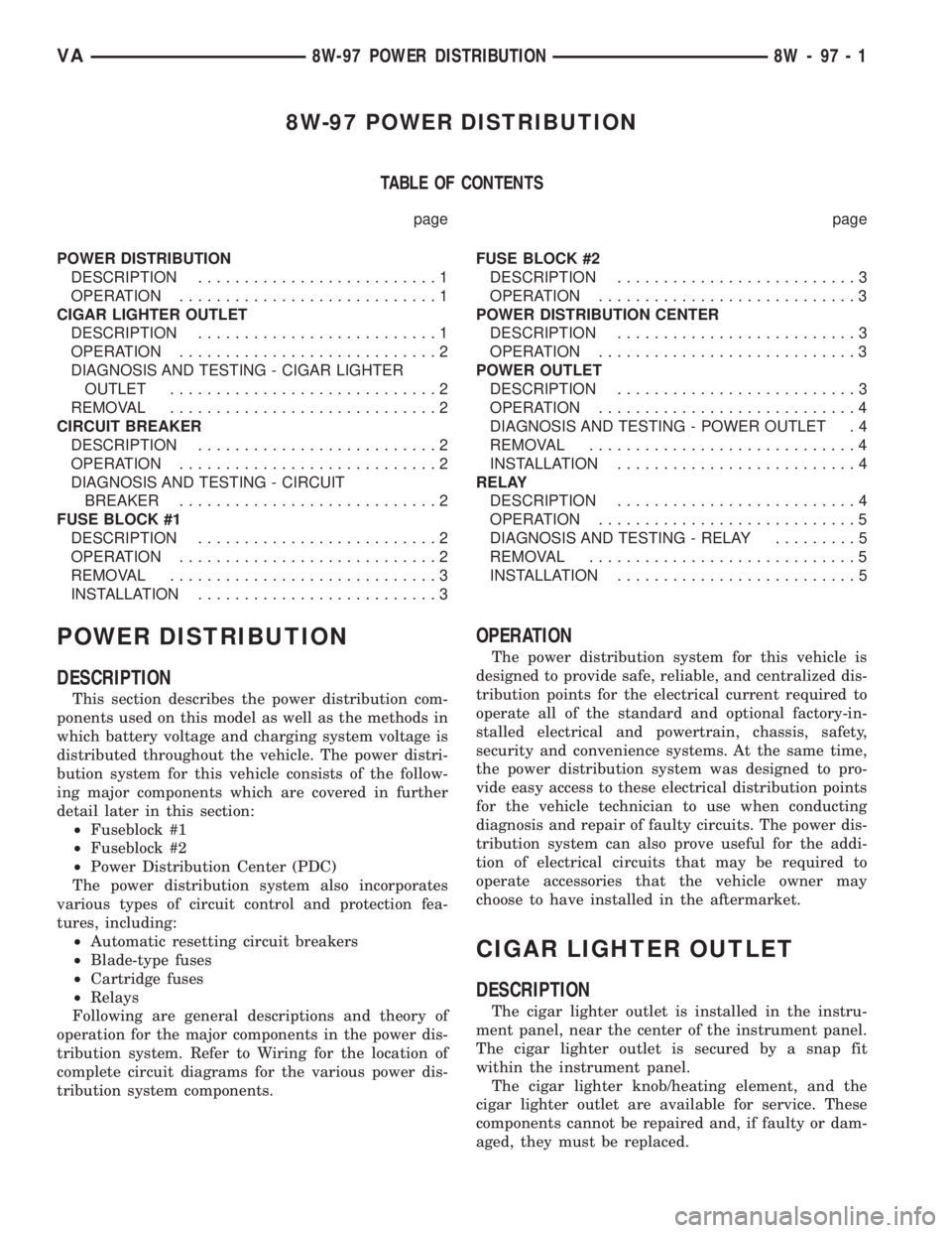
8W-97 POWER DISTRIBUTION
TABLE OF CONTENTS
page page
POWER DISTRIBUTION
DESCRIPTION..........................1
OPERATION............................1
CIGAR LIGHTER OUTLET
DESCRIPTION..........................1
OPERATION............................2
DIAGNOSIS AND TESTING - CIGAR LIGHTER
OUTLET.............................2
REMOVAL.............................2
CIRCUIT BREAKER
DESCRIPTION..........................2
OPERATION............................2
DIAGNOSIS AND TESTING - CIRCUIT
BREAKER............................2
FUSE BLOCK #1
DESCRIPTION..........................2
OPERATION............................2
REMOVAL.............................3
INSTALLATION..........................3FUSE BLOCK #2
DESCRIPTION..........................3
OPERATION............................3
POWER DISTRIBUTION CENTER
DESCRIPTION..........................3
OPERATION............................3
POWER OUTLET
DESCRIPTION..........................3
OPERATION............................4
DIAGNOSIS AND TESTING - POWER OUTLET . 4
REMOVAL.............................4
INSTALLATION..........................4
RELAY
DESCRIPTION..........................4
OPERATION............................5
DIAGNOSIS AND TESTING - RELAY.........5
REMOVAL.............................5
INSTALLATION..........................5
POWER DISTRIBUTION
DESCRIPTION
This section describes the power distribution com-
ponents used on this model as well as the methods in
which battery voltage and charging system voltage is
distributed throughout the vehicle. The power distri-
bution system for this vehicle consists of the follow-
ing major components which are covered in further
detail later in this section:
²Fuseblock #1
²Fuseblock #2
²Power Distribution Center (PDC)
The power distribution system also incorporates
various types of circuit control and protection fea-
tures, including:
²Automatic resetting circuit breakers
²Blade-type fuses
²Cartridge fuses
²Relays
Following are general descriptions and theory of
operation for the major components in the power dis-
tribution system. Refer to Wiring for the location of
complete circuit diagrams for the various power dis-
tribution system components.
OPERATION
The power distribution system for this vehicle is
designed to provide safe, reliable, and centralized dis-
tribution points for the electrical current required to
operate all of the standard and optional factory-in-
stalled electrical and powertrain, chassis, safety,
security and convenience systems. At the same time,
the power distribution system was designed to pro-
vide easy access to these electrical distribution points
for the vehicle technician to use when conducting
diagnosis and repair of faulty circuits. The power dis-
tribution system can also prove useful for the addi-
tion of electrical circuits that may be required to
operate accessories that the vehicle owner may
choose to have installed in the aftermarket.
CIGAR LIGHTER OUTLET
DESCRIPTION
The cigar lighter outlet is installed in the instru-
ment panel, near the center of the instrument panel.
The cigar lighter outlet is secured by a snap fit
within the instrument panel.
The cigar lighter knob/heating element, and the
cigar lighter outlet are available for service. These
components cannot be repaired and, if faulty or dam-
aged, they must be replaced.
VA8W-97 POWER DISTRIBUTION 8W - 97 - 1
Page 734 of 1232
OPERATION
The cigar lighter consists of two major components:
a knob and heating element unit, and the cigar
lighter base or receptacle shell. The receptacle shell
is connected to ground, and an insulated contact in
the bottom of the shell is connected to battery cur-
rent. The cigar lighter receives battery voltage from a
fuse in the fuseblock only when the ignition switch is
in the Accessory or On positions.
The knob and heating element are encased within
a spring-loaded housing, which also features a sliding
protective heat shield. When the heating element is
inserted in the receptacle shell, the heating element
resistor coil is grounded through its housing to the
receptacle shell. If the cigar lighter knob is pushed
inward, the heat shield slides up toward the knob
exposing the heating element.
Two small spring-clip retainers are located on
either side of the insulated contact inside the bottom
of the receptacle shell. These clips engage and hold
the heating element against the insulated contact
long enough for the resistor coil to heat up and glow.
When the resistor coil becomes sufficiently heated,
excess heat radiates from the heating element caus-
ing the spring-clips to expand. Once the spring-clips
expand far enough to release the heating element,
the spring-loaded housing forces the knob and heat-
ing element to pop back outward to their relaxed
position. When the cigar lighter knob and element
are pulled out of the receptacle shell, the protective
heat shield slides downward on the housing so that
the heating element is recessed and shielded around
its circumference for safety.
DIAGNOSIS AND TESTING - CIGAR LIGHTER
OUTLET
For cigar lighter outlet diagnosis and testing pro-
cedures (Refer to 8 - ELECTRICAL/POWER DISTRI-
BUTION/POWER OUTLET - DIAGNOSIS AND
TESTING)
REMOVAL
For cigar lighter outlet removal procedure (Refer to
8 - ELECTRICAL/POWER DISTRIBUTION/POWER
OUTLET - REMOVAL).
CIRCUIT BREAKER
DESCRIPTION
Automatic resetting circuit breakers are used to
protect the power window voltage supply circuits.
These circuit breakers can protect the systems from a
short circuit, or from an overload condition caused by
an obstructed or stuck power window regulator or
switch.The circuit breaker cannot be repaired and, if
faulty or damaged, it must be replaced.
OPERATION
The circuit breaker contains a bi-metal strip sand-
wiched between two contacts forming the connection
in the circuit. An overload condition causes the
bi-metal strip to heat and bend to the open position,
disconnecting current flow to the circuit. Then as the
system overload or short circuit is removed, the
bi-metal strip cools, re-establishing contact to allow
current flow to the circuit.
DIAGNOSIS AND TESTING - CIRCUIT BREAKER
For complete circuit descriptions and diagrams,
refer toWiring.
(1) Locate the correct circuit breaker in the fuse-
block. Pull out the circuit breaker slightly, but be cer-
tain that the circuit breaker terminals still contact
the terminals in the fuseblock cavities.
(2) Connect the negative lead of a 12-volt DC volt-
meter to a good ground.
(3) With the voltmeter positive lead, check both
terminals of the circuit breaker for battery voltage.
If only one terminal has battery voltage, the circuit
breaker is faulty and must be replaced. If neither ter-
minal has battery voltage, repair the open circuit
from the Power Distribution Center as required.
FUSE BLOCK #1
DESCRIPTION
An electrical fuse block is concealed under the
driver side steering column. The fuse block serves to
distribute electrical current to many of the electrical
systems in the vehicle. The fuse block contains blade-
type mini fuses, relays and micro processors that
enable automatic control of some of the power distri-
bution circuits throughout the vehicle.
The molded plastic fuse block housing has an inte-
gral mounting bracket that is secured with screws to
the steering column. A finger recess is molded into
the cover for easy removal. A fuse layout map is
molded onto the back side of the cover to ensure
proper fuse identification.
The fuse block cannot be repaired, if the fuse block
is faulty or damaged or if any internal circuit is
faulty or damaged, the entire fuse block must be
replaced.
OPERATION
All of the circuits entering and leaving the fuse
block do so through the instrument panel wire har-
ness. Internal connection of all of the fuse block cir-
cuits is accomplished by an intricate combination of
8W - 97 - 2 8W-97 POWER DISTRIBUTIONVA
CIGAR LIGHTER OUTLET (Continued)
Page 735 of 1232
hard wiring and bus bars. Internal relays and micro
processors allow the vehicle electronics to control
some of the power distribution circuits throughout
the vehicle. Refer to the Wiring section for complete
circuit diagrams.
REMOVAL
(1) Disconnect and isolate the negative battery
cable.
(2) Remove fuse block cover by rotating locking
screw 90É.
(3) Remove the steering column cover. Refer to the
Body section for the procedure.
(4) Unscrew fuse block connections and disconnect
all electrical connectors from the fuse block.
(5) Remove the fuse block from the steering col-
umn.
INSTALLATION
(1) Position the fuse block in the steering column.
(2) Install fuse block connections and connect all
electrical connectors on the fuse block.
(3) Install the steering column cover. Refer to the
Body section for the procedure.
(4) Install fuse block cover by rotating locking
screw 90É.
(5) Connect the negative battery cable.
(6) Set time and radio stations.
FUSE BLOCK #2
DESCRIPTION
An electrical fuse block is concealed under the
driver side front seat. The fuse block serves to dis-
tribute electrical current to many of the electrical
systems in the vehicle. The fuse block houses blade-
type mini fuses, blade-type automatic resetting cir-
cuit breakers and International Standards
Organization relays. Additional provisions are avail-
able in the fuse block for additional fuses and ISO
relays.
The molded plastic fuse block housing has an inte-
gral mounting bracket that is secured with screws to
the seat base. The driver side seat base also has a
snap-fit fuse access panel that can be removed for
service of the fuses and the relays. A finger recess is
molded into one end for easy removal. A fuse layout
map is molded onto the back side of the panel to
ensure proper fuse identification.
The fuse block is integral to the body wire harness.
If any internal circuit or the fuse block housing is
faulty or damaged, the entire fuse block and body
wire harness unit must be replaced.
OPERATION
All of the circuits entering and leaving the fuse
block do so through the body wire harness. Internal
connection of all of the fuse block circuits is accom-
plished by an intricate combination of hard wiring
and bus bars.
POWER DISTRIBUTION
CENTER
DESCRIPTION
All of the electrical current distributed throughout
this vehicle is directed through the Power Distribu-
tion Center (PDC). The molded plastic PDC housing
is located in the left front corner of the engine com-
partment, on the battery positive cable. The PDC
housing has a molded plastic cover that slides over
the PDC housing. The PDC cover is easily opened or
removed for service access.
The PDC unit cannot be repaired and is only ser-
viced as a unit with the headlamp and dash wire
harness. If the internal circuits or the PDC housing
are faulty or damaged, the headlamp and dash wire
harness unit must be replaced.
OPERATION
All of the current from the battery and the gener-
ator output enters the PDC through the positive bat-
tery cable. The PDC cover is removed to access the
battery and generator output connection B(+) termi-
nal studs. Internal connection of all of the PDC cir-
cuits is accomplished by an intricate combination of
hard wiring and bus bars. Refer to Wiring Diagrams
for the location of complete PDC circuit diagrams.
POWER OUTLET
DESCRIPTION
The power outlet is installed in the instrument
panel accessory switch plate, which is located near
the center of the instrument panel. The power outlet
base is secured by a snap fit within the instrument
panel. A plastic protective cap snaps over the power
outlet base when the power outlet is not being used.
While the power outlet is very similar to a cigar
lighter base unit, it does not include the two small
spring-clip retainers inside the bottom of the recepta-
cle shell that are used to secure the cigar lighter
heating element to the insulated contact.
The power outlet receptacle unit are available for
service. The power outlet receptacle cannot be
repaired and, if faulty or damaged, it must be
replaced.
VA8W-97 POWER DISTRIBUTION 8W - 97 - 3
FUSE BLOCK #1 (Continued)
Page 736 of 1232
OPERATION
The power outlet base or receptacle shell is con-
nected to ground, and an insulated contact in the
bottom of the shell is connected to battery current.
The power outlet receives battery voltage from a fuse
in the fuse block at all times.
DIAGNOSIS AND TESTING - POWER OUTLET
(1) Check for battery voltage at the fused B(+) fuse
in the fuse block. If OK, go to Step 2. If not OK,
repair the open fused B(+) circuit to the battery as
required.
(2) Check for continuity between the inside cir-
cumference of the power outlet receptacle and a good
ground. There should be continuity. If OK, go to Step
3. If not OK, go to Step 4.
(3) Check for battery voltage at the insulated con-
tact located at the back of the power outlet recepta-
cle. If not OK, go to Step 4.
(4) Disconnect and isolate the battery negative
cable. Check for continuity between the ground cir-
cuit cavity of the power outlet wire harness connector
and a good ground. There should be continuity. If
OK, go to Step 5. If not OK, repair the open ground
circuit to ground as required.
(5) Connect the battery negative cable. Check for
battery voltage at the fused B(+) circuit cavity of the
power outlet wire harness connector. If OK, replace
the faulty power outlet receptacle. If not OK, repair
the open fused B(+) circuit to the fuse in the fuse
block as required.
REMOVAL
(1) Disconnect and isolate the battery negative
cable.
(2) Pull the cigar lighter knob and element out of
the cigar lighter receptacle base, or unsnap the pro-
tective cap from the power outlet receptacle base.
(3) Look inside the cigar lighter or power outlet
receptacle base and note the position of the rectangu-
lar retaining bosses of the mount that secures the
receptacle base to the instrument panel.
(4) Insert a pair of external snap ring pliers into
the cigar lighter or power outlet receptacle base and
engage the tips of the pliers with the retaining
bosses of the mount.
(5) Squeeze the pliers to disengage the mount
retaining bosses from the receptacle base and, using
a gentle rocking motion, pull the pliers and the
receptacle base out of the mount.
(6) Disconnect the instrument panel wire harness
connector from the connector receptacle of the cigar
lighter or the power outlet receptacle base.
(7) Remove the cigar lighter or power outlet mount
from the instrument panel.
INSTALLATION
(1) Install the cigar lighter or power outlet mount
into the instrument panel.
(2) Reconnect the instrument panel wire harness
connector to the connector receptacle of the cigar
lighter or the power outlet receptacle base.
(3) Align the splines on the outside of the cigar
lighter or power outlet receptacle base connector
receptacle with the grooves on the inside of the
mount.
(4) Press firmly on the cigar lighter or power out-
let receptacle base until the retaining bosses of the
mount are fully engaged in their receptacles.
(5) Install the cigar lighter knob and element into
the cigar lighter receptacle base.
(6) Reconnect the battery negative cable.
RELAY
DESCRIPTION
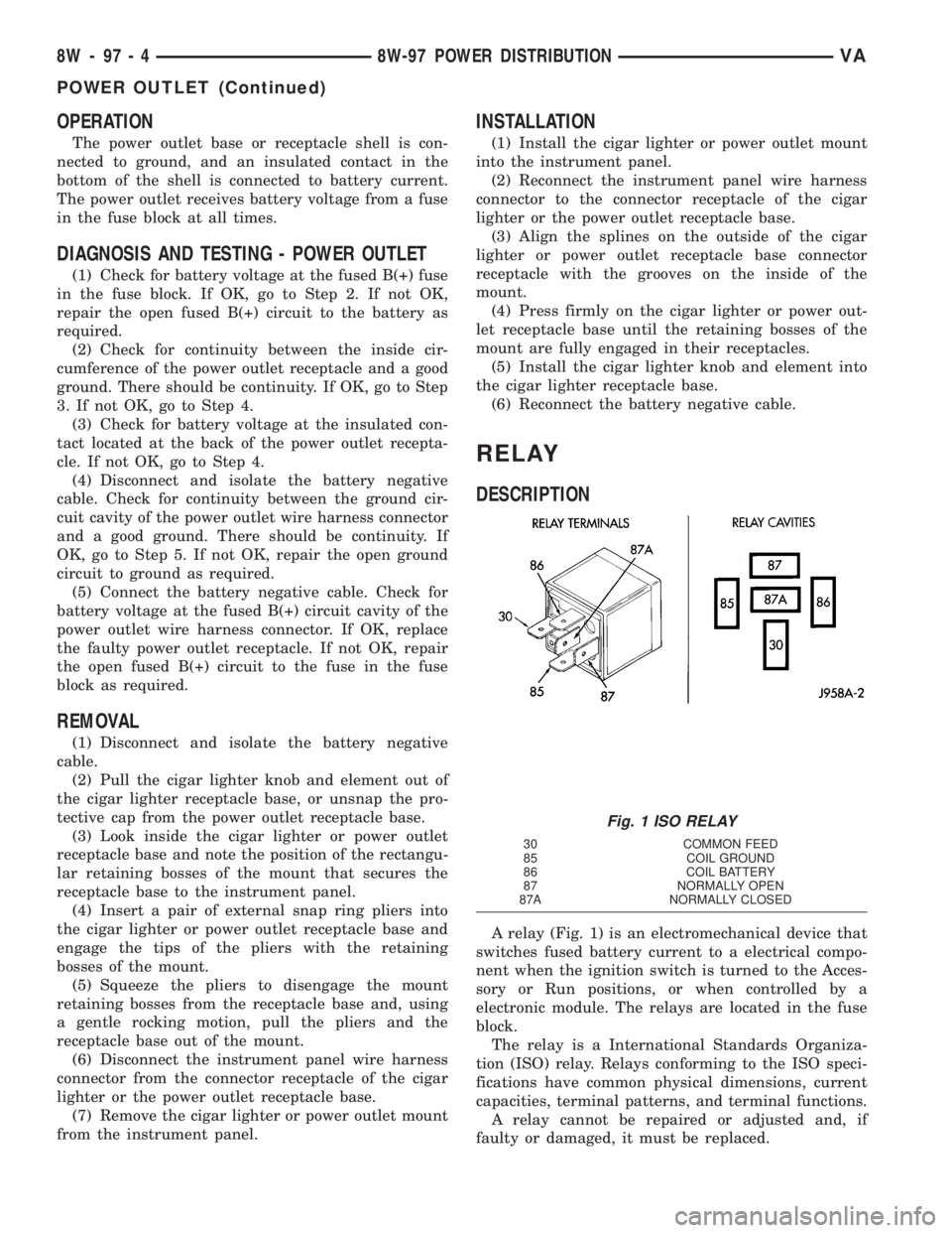
A relay (Fig. 1) is an electromechanical device that
switches fused battery current to a electrical compo-
nent when the ignition switch is turned to the Acces-
sory or Run positions, or when controlled by a
electronic module. The relays are located in the fuse
block.
The relay is a International Standards Organiza-
tion (ISO) relay. Relays conforming to the ISO speci-
fications have common physical dimensions, current
capacities, terminal patterns, and terminal functions.
A relay cannot be repaired or adjusted and, if
faulty or damaged, it must be replaced.
Fig. 1 ISO RELAY
30 COMMON FEED
85 COIL GROUND
86 COIL BATTERY
87 NORMALLY OPEN
87A NORMALLY CLOSED
8W - 97 - 4 8W-97 POWER DISTRIBUTIONVA
POWER OUTLET (Continued)
Page 737 of 1232
OPERATION
The ISO relay consists of an electromagnetic coil, a
resistor and three (two fixed and one movable) elec-
trical contacts. The movable (common feed) relay con-
tact is held against one of the fixed contacts
(normally closed) by spring pressure. When the elec-
tromagnetic coil is energized, it draws the movable
contact away from the normally closed fixed contact,
and holds it against the other (normally open) fixed
contact.
When the electromagnetic coil is de-energized,
spring pressure returns the movable contact to the
normally closed position. The resistor is connected in
parallel with the electromagnetic coil in the relay,
and helps to dissipate voltage spikes that are pro-
duced when the coil is de-energized.
DIAGNOSIS AND TESTING - RELAY
(1) Remove the relay from its mounting location.
(2) A relay in the de-energized position should
have continuity between terminals 87A and 30, and
no continuity between terminals 87 and 30. If OK, go
to Step 3. If not OK, replace the faulty relay.
(3) Resistance between terminals 85 and 86 (elec-
tromagnet) should be 60.7 - 80.3 ohms. If OK, go to
Step 4. If not OK, replace the faulty relay.
(4) Connect a battery to terminals 85 and 86.
There should now be continuity between terminals
30 and 87, and no continuity between terminals 87A
and 30. If OK, perform the Relay Circuit Test that
follows. If not OK, replace the faulty relay.
DIAGNOSIS AND TESTING - RELAY CIRCUIT TEST
(1) The relay common feed terminal cavity (30) of
the fuse block is connected to battery voltage and
should be hot at all times. Check for battery voltage
at the fused B(+) circuit cavity in the fuse block
receptacle for the relay. If OK, go to Step 2. If not
OK, repair the fused B(+) circuit to the fuse block
fuse as required.
(2) The relay normally closed terminal (87A) is
connected to terminal 30 in the de-energized position,
but is not used for this application. Go to Step 3.(3) The relay normally open terminal (87) is con-
nected to the common feed terminal (30) in the ener-
gized position. This terminal supplies battery voltage
to the fused B(+) fuse in the fuse block that feeds the
accessory when the relay is energized by the ignition
switch. There should be continuity between the fuse
block cavity for relay terminal 87 and the fused B(+)
fuse in the fuse block at all times. If OK, go to Step
4. If not OK, repair the open fused B(+) circuit to the
fuse block fuse as required.
(4) The coil ground terminal (85) is connected to
the electromagnet in the relay. It receives battery
feed to energize the relay when the ignition switch is
in the Accessory or Run positions. Turn the ignition
switch to the On position. Check for battery voltage
at the fused ignition switch output (acc/run) circuit
cavity for relay terminal 85 in the fuse block recep-
tacle for the relay. If OK, go to Step 5. If not OK,
repair the open fused ignition switch output (acc/run)
circuit to the ignition switch as required.
(5) The coil battery terminal (86) is connected to
the electromagnet in the relay. The fuse block cavity
for this terminal should have continuity to ground at
all times. If not OK, repair the open ground circuit to
ground as required.
REMOVAL
(1) Disconnect and isolate the negative battery
cable.
(2) Remove the relay by grasping it firmly and
pulling it straight out from its receptacle. A slight
back and fourth rocking motion may help the
removal process.
INSTALLATION
(1) Position the relay to the proper receptacle.
(2) Align the relay terminals with the terminal
cavities in the receptacle.
(3) Push firmly and evenly on the top of the relay
until the terminals are fully seated in the terminal
cavities in the receptacle.
(4) Connect the negative battery cable.
VA8W-97 POWER DISTRIBUTION 8W - 97 - 5
RELAY (Continued)
Page 794 of 1232
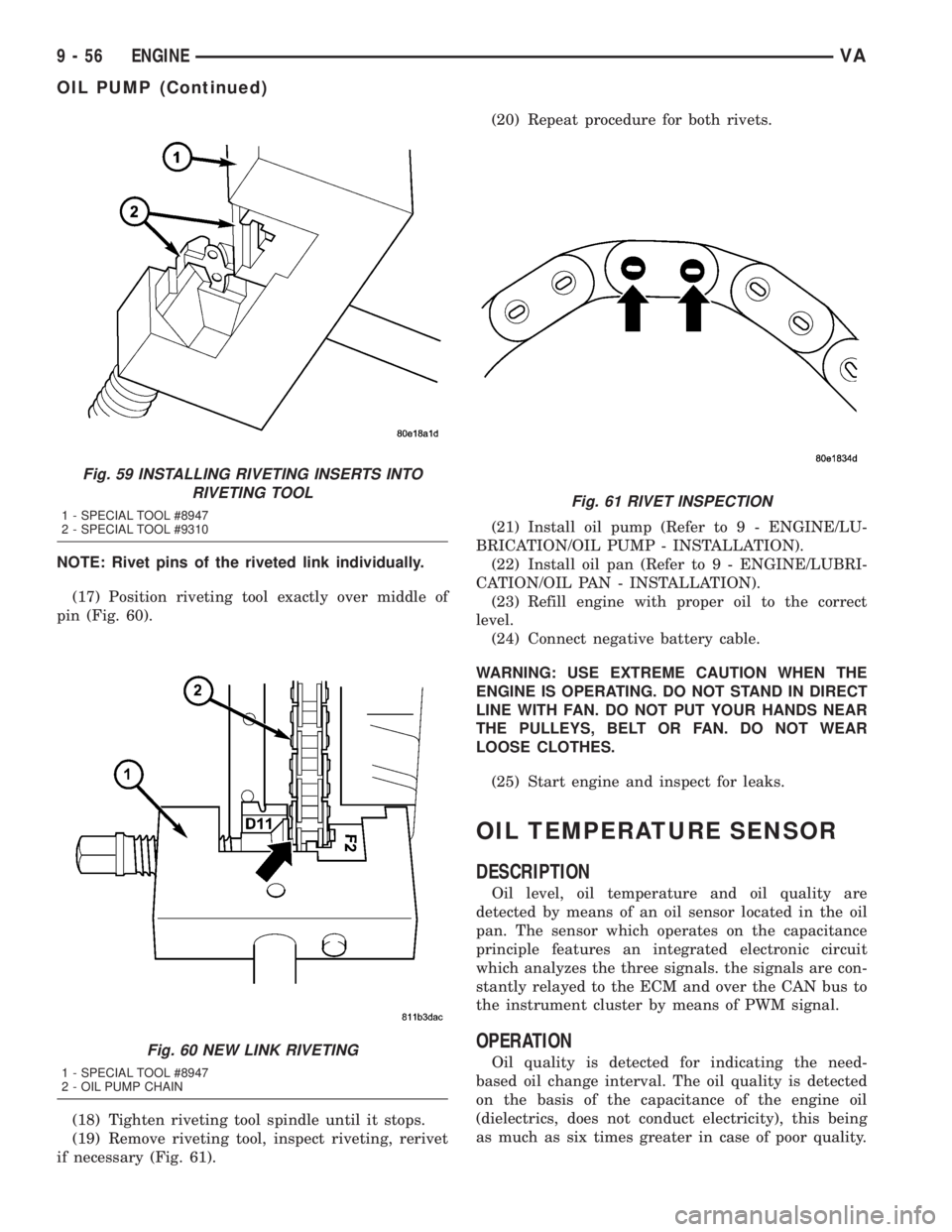
NOTE: Rivet pins of the riveted link individually.
(17) Position riveting tool exactly over middle of
pin (Fig. 60).
(18) Tighten riveting tool spindle until it stops.
(19) Remove riveting tool, inspect riveting, rerivet
if necessary (Fig. 61).(20) Repeat procedure for both rivets.
(21) Install oil pump (Refer to 9 - ENGINE/LU-
BRICATION/OIL PUMP - INSTALLATION).
(22) Install oil pan (Refer to 9 - ENGINE/LUBRI-
CATION/OIL PAN - INSTALLATION).
(23) Refill engine with proper oil to the correct
level.
(24) Connect negative battery cable.
WARNING: USE EXTREME CAUTION WHEN THE
ENGINE IS OPERATING. DO NOT STAND IN DIRECT
LINE WITH FAN. DO NOT PUT YOUR HANDS NEAR
THE PULLEYS, BELT OR FAN. DO NOT WEAR
LOOSE CLOTHES.
(25) Start engine and inspect for leaks.
OIL TEMPERATURE SENSOR
DESCRIPTION
Oil level, oil temperature and oil quality are
detected by means of an oil sensor located in the oil
pan. The sensor which operates on the capacitance
principle features an integrated electronic circuit
which analyzes the three signals. the signals are con-
stantly relayed to the ECM and over the CAN bus to
the instrument cluster by means of PWM signal.
OPERATION
Oil quality is detected for indicating the need-
based oil change interval. The oil quality is detected
on the basis of the capacitance of the engine oil
(dielectrics, does not conduct electricity), this being
as much as six times greater in case of poor quality.
Fig. 59 INSTALLING RIVETING INSERTS INTO
RIVETING TOOL
1 - SPECIAL TOOL #8947
2 - SPECIAL TOOL #9310
Fig. 60 NEW LINK RIVETING
1 - SPECIAL TOOL #8947
2 - OIL PUMP CHAIN
Fig. 61 RIVET INSPECTION
9 - 56 ENGINEVA
OIL PUMP (Continued)
Page 1150 of 1232
CONTROLS - REAR
TABLE OF CONTENTS
page page
BLOWER MOTOR SWITCH
DESCRIPTION.........................22
OPERATION...........................22
DIAGNOSIS AND TESTING................23
REMOVAL.............................23
INSTALLATION.........................23
BLOWER MOTOR RELAY
DESCRIPTION.........................23
OPERATION...........................23
DIAGNOSIS AND TESTING................24
REMOVAL.............................24
INSTALLATION.........................24
CONTROL MODULE
DESCRIPTION.........................24
OPERATION...........................24
DIAGNOSIS AND TESTING................24
REMOVAL.............................24
INSTALLATION.........................25
EVAPORATOR TEMPERATURE SENSOR
DESCRIPTION.........................25
OPERATION...........................26DIAGNOSIS AND TESTING................26
REMOVAL.............................26
INSTALLATION.........................26
SOLENOID VALVE
DESCRIPTION.........................27
OPERATION...........................27
DIAGNOSIS AND TESTING................27
REMOVAL.............................27
INSTALLATION.........................28
TEMPERATURE CONTROL
DESCRIPTION.........................29
OPERATION...........................29
DIAGNOSIS AND TESTING................29
REMOVAL.............................29
INSTALLATION.........................29
TEMPERATURE SENSOR
DESCRIPTION.........................30
OPERATION...........................30
DIAGNOSIS AND TESTING................30
REMOVAL.............................30
INSTALLATION.........................30
BLOWER MOTOR SWITCH
DESCRIPTION
The optional rear A/C unit blower motor is con-
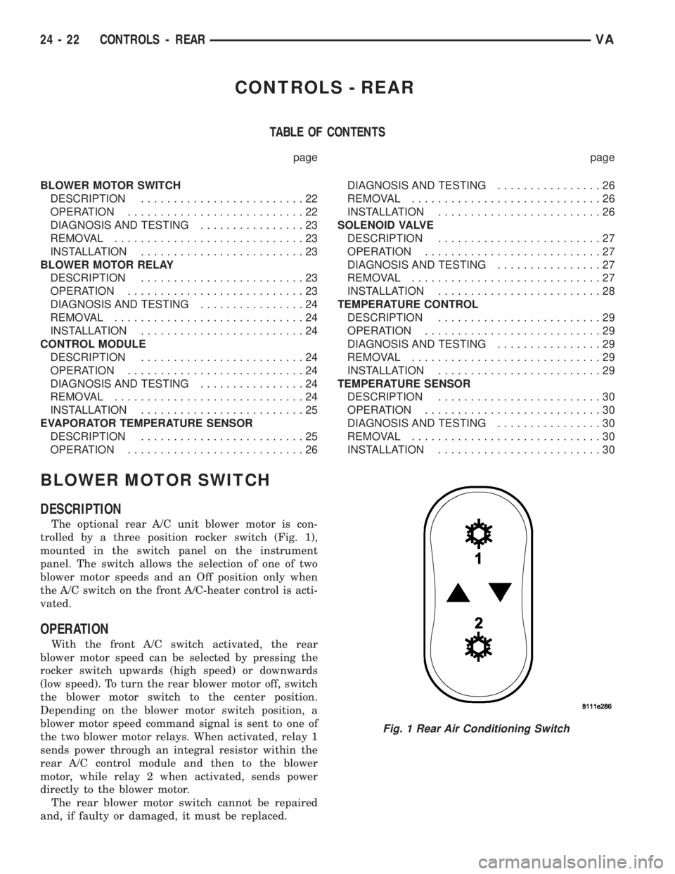
trolled by a three position rocker switch (Fig. 1),
mounted in the switch panel on the instrument
panel. The switch allows the selection of one of two
blower motor speeds and an Off position only when
the A/C switch on the front A/C-heater control is acti-
vated.
OPERATION
With the front A/C switch activated, the rear
blower motor speed can be selected by pressing the
rocker switch upwards (high speed) or downwards
(low speed). To turn the rear blower motor off, switch
the blower motor switch to the center position.
Depending on the blower motor switch position, a
blower motor speed command signal is sent to one of
the two blower motor relays. When activated, relay 1
sends power through an integral resistor within the
rear A/C control module and then to the blower
motor, while relay 2 when activated, sends power
directly to the blower motor.
The rear blower motor switch cannot be repaired
and, if faulty or damaged, it must be replaced.
Fig. 1 Rear Air Conditioning Switch
24 - 22 CONTROLS - REARVA