2005 MERCEDES-BENZ SPRINTER air condition
[x] Cancel search: air conditionPage 1194 of 1232
REFRIGERANT OIL CAPACITIES
Component ml fl oz
Total System Fill410 (425
w/rear A/C)13.9 (14.4
w/rear A/C
Receiver/Drier 30 1.0
Condenser 30 1.0
Front Evaporator 60 2.0
Rear Evaporator 30 1.0
CompressorDrain and measure the oil
from the old compressor -
see text.
SUCTION LINE
REMOVAL
WARNING: REVIEW THE WARNINGS AND CAU-
TIONS IN THE FRONT OF THIS SECTION BEFORE
PERFORMING THE FOLLOWING OPERATION (Refer
to 24 - HEATING & AIR CONDITIONING/PLUMBING -
WARNING) and (Refer to 24 - HEATING & AIR CON-
DITIONING/PLUMBING - CAUTION).
(1) Recover the refrigerant system. (Refer to 24 -
HEATING & AIR CONDITIONING/PLUMBING -
STANDARD PROCEDURE - REFRIGERANT
RECOVERY)
(2) Disconnect and isolate the negative battery
cable.
(3) Remove the routing clip retaining nut and dis-
engage the metal routing clip from the suction line.
(4) Disengage the plastic routing clip located near
the expansion valve from the suction line.
(5) Remove the nut that secures the suction and
liquid line fittings to the stud on the expansion valve
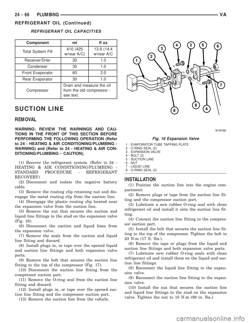
(Fig. 16).
(6) Disconnect the suction and liquid lines from
the expansion valve.
(7) Remove the seals from the suction and liquid
line fitting and discard.
(8) Install plugs in, or tape over the opened liquid
and suction line fittings and both expansion valve
ports.
(9) Remove the bolt that secures the suction line
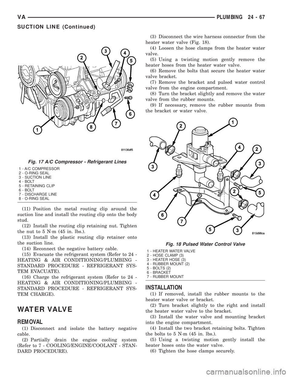
fitting to the top of the compressor (Fig. 17).
(10) Disconnect the suction line fitting from the
compressor suction port.
(11) Remove the O-ring seal from the suction line
fitting and discard.
(12) Install plugs in, or tape over the opened suc-
tion line fitting and the compressor suction port.
(13) Remove the suction line from the vehicle.
INSTALLATION
(1) Position the suction line into the engine com-
partment.
(2) Remove plugs or tape from the suction line fit-
ting and the compressor suction port.
(3) Lubricate a new rubber O-ring seal with clean
refrigerant oil and install it onto the suction line fit-
ting.
(4) Connect the suction line fitting to the compres-
sor suction port.
(5) Install the bolt that secures the suction line fit-
ting to the top of the compressor. Tighten the bolt to
23 N´m (17 ft. lbs.).
(6) Remove the tape or plugs from the liquid and
suction line fittings and both expansion valve ports.
(7) Lubricate new rubber O-ring seals with clean
refrigerant oil and install them on the liquid and suc-
tion line fittings.
(8) Reconnect the liquid line fitting to the expan-
sion valve.
(9) Reconnect the suction line fitting to the expan-
sion valve.
(10) Install the nut that secures the suction line
and liquid line fittings to the stud on the expansion
valve. Tighten the nut to 10 N´m (89 in. lbs.).
Fig. 16 Expansion Valve
1 - EVAPORATOR TUBE TAPPING PLATE
2 - O-RING SEAL (2)
3 - EXPANSION VALVE
4 - BOLT (2)
5 - SUCTION LINE
6 - NUT
7 - LIQUID LINE
8 - O-RING SEAL (2)
24 - 66 PLUMBINGVA
REFRIGERANT OIL (Continued)
Page 1195 of 1232
(11) Position the metal routing clip around the
suction line and install the routing clip onto the body
stud.
(12) Install the routing clip retaining nut. Tighten
the nut to 5 N´m (45 in. lbs.).
(13) Install the plastic routing clip retainer onto
the suction line.
(14) Reconnect the negative battery cable.
(15) Evacuate the refrigerant system (Refer to 24 -
HEATING & AIR CONDITIONING/PLUMBING -
STANDARD PROCEDURE - REFRIGERANT SYS-
TEM EVACUATE).
(16) Charge the refrigerant system (Refer to 24 -
HEATING & AIR CONDITIONING/PLUMBING -
STANDARD PROCEDURE - REFRIGERANT SYS-
TEM CHARGE).
WATER VALVE
REMOVAL
(1) Disconnect and isolate the battery negative
cable.
(2) Partially drain the engine cooling system
(Refer to 7 - COOLING/ENGINE/COOLANT - STAN-
DARD PROCEDURE).(3) Disconnect the wire harness connector from the
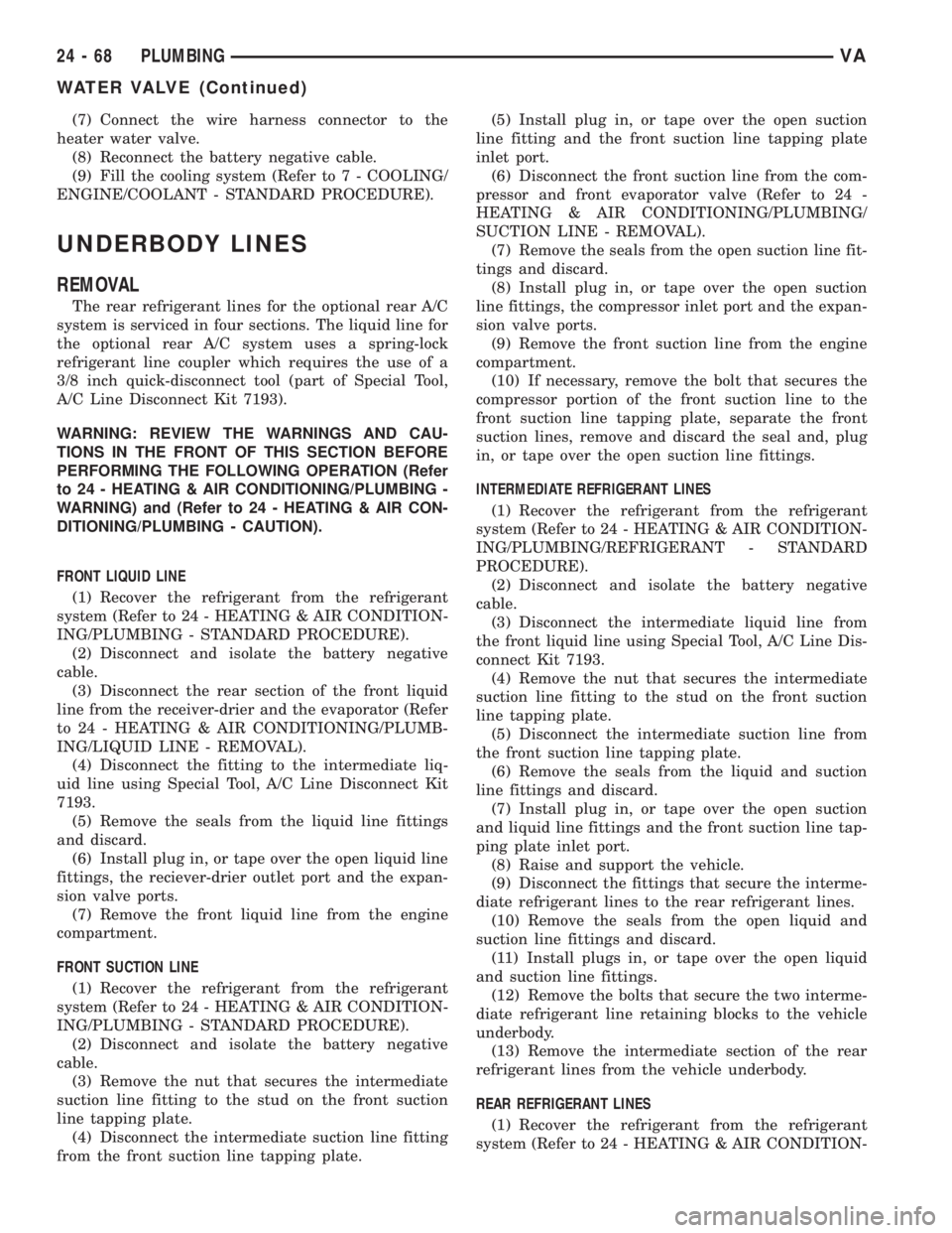
heater water valve (Fig. 18).
(4) Loosen the hose clamps from the heater water
valve.
(5) Using a twisting motion gently remove the
heater hoses from the heater water valve.
(6) Remove the bolts that secure the heater water
valve bracket.
(7) Remove the bracket and pulsed water control
valve from the engine compartment.
(8) Turn the bracket slightly and remove the water
valve from the rubber mounts.
(9) If necessary, remove the rubber mounts from
the bracket or water valve.
INSTALLATION
(1) If removed, install the rubber mounts to the
heater water valve or bracket.
(2) Turn bracket slightly to the right and install
the heater water valve to the bracket.
(3) Install the water valve and mounting bracket
into the engine compartment.
(4) Install the two bracket retaining bolts. Tighten
the bolts to 5 N´m (45 in. lbs.).
(5) Using a twisting motion gently install the
heater hoses onto the water valve.
(6) Tighten the hose clamps securely.
Fig. 17 A/C Compressor - Refrigerant Lines
1 - A/C COMPRESSOR
2 - O-RING SEAL
3 - SUCTION LINE
4 - BOLT
5 - RETAINING CLIP
6 - BOLT
7 - DISCHARGE LINE
8 - O-RING SEAL
Fig. 18 Pulsed Water Control Valve
1 - HEATER WATER VALVE
2 - HOSE CLAMP (3)
3 - HEATER HOSE (3)
4 - RUBBER MOUNT (2)
5 - BOLTS (2)
6 - BRACKET
7 - RUBBER MOUNT
VAPLUMBING 24 - 67
SUCTION LINE (Continued)
Page 1196 of 1232
(7) Connect the wire harness connector to the
heater water valve.
(8) Reconnect the battery negative cable.
(9) Fill the cooling system (Refer to 7 - COOLING/
ENGINE/COOLANT - STANDARD PROCEDURE).
UNDERBODY LINES
REMOVAL
The rear refrigerant lines for the optional rear A/C
system is serviced in four sections. The liquid line for
the optional rear A/C system uses a spring-lock
refrigerant line coupler which requires the use of a
3/8 inch quick-disconnect tool (part of Special Tool,
A/C Line Disconnect Kit 7193).
WARNING: REVIEW THE WARNINGS AND CAU-
TIONS IN THE FRONT OF THIS SECTION BEFORE
PERFORMING THE FOLLOWING OPERATION (Refer
to 24 - HEATING & AIR CONDITIONING/PLUMBING -
WARNING) and (Refer to 24 - HEATING & AIR CON-
DITIONING/PLUMBING - CAUTION).
FRONT LIQUID LINE
(1) Recover the refrigerant from the refrigerant
system (Refer to 24 - HEATING & AIR CONDITION-
ING/PLUMBING - STANDARD PROCEDURE).
(2) Disconnect and isolate the battery negative
cable.
(3) Disconnect the rear section of the front liquid
line from the receiver-drier and the evaporator (Refer
to 24 - HEATING & AIR CONDITIONING/PLUMB-
ING/LIQUID LINE - REMOVAL).
(4) Disconnect the fitting to the intermediate liq-
uid line using Special Tool, A/C Line Disconnect Kit
7193.
(5) Remove the seals from the liquid line fittings
and discard.
(6) Install plug in, or tape over the open liquid line
fittings, the reciever-drier outlet port and the expan-
sion valve ports.
(7) Remove the front liquid line from the engine
compartment.
FRONT SUCTION LINE
(1) Recover the refrigerant from the refrigerant
system (Refer to 24 - HEATING & AIR CONDITION-
ING/PLUMBING - STANDARD PROCEDURE).
(2) Disconnect and isolate the battery negative
cable.
(3) Remove the nut that secures the intermediate
suction line fitting to the stud on the front suction
line tapping plate.
(4) Disconnect the intermediate suction line fitting
from the front suction line tapping plate.(5) Install plug in, or tape over the open suction
line fitting and the front suction line tapping plate
inlet port.
(6) Disconnect the front suction line from the com-
pressor and front evaporator valve (Refer to 24 -
HEATING & AIR CONDITIONING/PLUMBING/
SUCTION LINE - REMOVAL).
(7) Remove the seals from the open suction line fit-
tings and discard.
(8) Install plug in, or tape over the open suction
line fittings, the compressor inlet port and the expan-
sion valve ports.
(9) Remove the front suction line from the engine
compartment.
(10) If necessary, remove the bolt that secures the
compressor portion of the front suction line to the
front suction line tapping plate, separate the front
suction lines, remove and discard the seal and, plug
in, or tape over the open suction line fittings.
INTERMEDIATE REFRIGERANT LINES
(1) Recover the refrigerant from the refrigerant
system (Refer to 24 - HEATING & AIR CONDITION-
ING/PLUMBING/REFRIGERANT - STANDARD
PROCEDURE).
(2) Disconnect and isolate the battery negative
cable.
(3) Disconnect the intermediate liquid line from
the front liquid line using Special Tool, A/C Line Dis-
connect Kit 7193.
(4) Remove the nut that secures the intermediate
suction line fitting to the stud on the front suction
line tapping plate.
(5) Disconnect the intermediate suction line from
the front suction line tapping plate.
(6) Remove the seals from the liquid and suction
line fittings and discard.
(7) Install plug in, or tape over the open suction
and liquid line fittings and the front suction line tap-
ping plate inlet port.
(8) Raise and support the vehicle.
(9) Disconnect the fittings that secure the interme-
diate refrigerant lines to the rear refrigerant lines.
(10) Remove the seals from the open liquid and
suction line fittings and discard.
(11) Install plugs in, or tape over the open liquid
and suction line fittings.
(12) Remove the bolts that secure the two interme-
diate refrigerant line retaining blocks to the vehicle
underbody.
(13) Remove the intermediate section of the rear
refrigerant lines from the vehicle underbody.
REAR REFRIGERANT LINES
(1) Recover the refrigerant from the refrigerant
system (Refer to 24 - HEATING & AIR CONDITION-
24 - 68 PLUMBINGVA
WATER VALVE (Continued)
Page 1197 of 1232
ING/PLUMBING/REFRIGERANT - STANDARD
PROCEDURE).
(2) Disconnect and isolate the battery negative
cable.
(3) Remove the interior trim panel from the right
quarter panel (Refer to 23 - BODY/INTERIOR/
QUARTER TRIM PANEL - REMOVAL).
(4) Disconnect the fittings that secure the rear
refrigerant lines to the sidewall refrigerant lines.
(5) Remove the seals from the open liquid and suc-
tion line fittings and discard.
(6) Install plugs in, or tape over the open liquid
and suction line fittings.
(7) Raise and support the vehicle.
(8) Disconnect the fittings that secure the interme-
diate refrigerant lines to the rear refrigerant lines.
(9) Remove the seals from the open liquid and suc-
tion line fittings and discard.
(10) Install plugs in, or tape over the open liquid
and suction line fittings.
(11) Remove the propeller shaft (Refer to 3 - DIF-
FERENTIAL & DRIVELINE/PROPELLER SHAFT/
PROPELLER SHAFT - REMOVAL).
(12) Remove the seal from the right inner sidewall.
(13) Carefully pull the rubber rear refrigerant
lines out from the sidewall.
(14) Remove the bolts that secure the four rear
refrigerant line retaining blocks to the vehicle under-
body.
(15) Remove the rear section of the rear refriger-
ant lines from the vehicle underbody.
SIDEWALL REFRIGERANT LINES
(1) Recover the refrigerant from the refrigerant
system (Refer to 24 - HEATING & AIR CONDITION-
ING/PLUMBING/REFRIGERANT - STANDARD
PROCEDURE).
(2) Disconnect and isolate the battery negative
cable.
(3) Disconnect the suction line from the rear
expansion valve outlet port (Refer to 24 - HEATING
& AIR CONDITIONING/PLUMBING/REAR EXPAN-
SION VALVE - REMOVAL).
(4) Disconnect the liquid line from rear solenoid
valve inlet port (Refer to 24 - HEATING & AIR CON-
DITIONING/CONTROLS/SOLENOID - REMOVAL).
(5) Remove the seals from the open liquid and suc-
tion line fittings and discard.
(6) Install plugs in, or tape over the open liquid
and suction line fittings and, the rear solenoid and
expansion valve ports.
(7) Remove the interior trim panel from the right
quarter panel (Refer to 23 - BODY/INTERIOR/
QUARTER TRIM PANEL - REMOVAL).
(8) Disconnect the fittings that secure the rear
refrigerant lines to the sidewall refrigerant lines.(9) Remove the seals from the open liquid and suc-
tion line fittings and discard.
(10) Install plugs in, or tape over the open liquid
and suction line fittings.
(11) Remove the bolts that secure the two refriger-
ant line retaining blocks to the vehicle sidewall.
(12) Carefully pull the rubber refrigerant lines out
from the sidewall.
(13) Remove the sidewall section of the rear refrig-
erant lines from the vehicle.
INSTALLATION
FRONT LIQUID LINE
(1) Install the front liquid line into the engine
compartment.
(2) Remove plugs or tape from the liquid line fit-
tings, the reciever-drier outlet port and the expan-
sion valve ports.
(3) Lubricate new rubber o-ring seals with clean
refrigerant oil and install the seals onto the liquid
line fittings.
(4) Connect the quick-disconnect front liquid line
fitting to the intermediate liquid line.
(5) Connect the rear section of the front liquid line
to the receiver-drier and the evaporator (Refer to 24 -
HEATING & AIR CONDITIONING/PLUMBING/
LIQUID LINE - INSTALLATION).
(6) Reconnect the battery negative cable.
(7) Evacuate the refrigerant system (Refer to 24 -
HEATING & AIR CONDITIONING/PLUMBING -
STANDARD PROCEDURE - REFRIGERANT SYS-
TEM EVACUATE).
(8) Charge the refrigerant system (Refer to 24 -
HEATING & AIR CONDITIONING/PLUMBING -
STANDARD PROCEDURE - REFRIGERANT SYS-
TEM CHARGE).
FRONT SUCTION LINE
(1) If the compressor portion of the front suction
line was separated from the front suction line tap-
ping plate, remove plugs or tape from the suction
line fitting, lubricate a new rubber o-ring seal with
clean refrigerant oil and install the seal onto the suc-
tion line fitting and, install the bolt that secures the
compressor portion of the front suction line to the
front suction line tapping plate. Tighten the bolt to 5
N´m (45 in. lbs.).
(2) Install the front suction line into the engine
compartment.
(3) Remove plugs or tape from the suction line fit-
tings, the compressor inlet port and the expansion
valve ports.
(4) Lubricate new rubber o-ring seals with clean
refrigerant oil and install the seals onto the suction
line fittings.
VAPLUMBING 24 - 69
UNDERBODY LINES (Continued)
Page 1198 of 1232
(5) Connect the front suction line to the compres-
sor and front evaporator valve (Refer to 24 - HEAT-
ING & AIR CONDITIONING/PLUMBING/SUCTION
LINE - INSTALLATION).
(6) Remove plugs or tape from the intermediate
suction line fitting and the front suction line tapping
plate inlet port.
(7) Lubricate a new rubber o-ring seal with clean
refrigerant oil and install the seal onto the interme-
diate suction line fitting.
(8) Connect the intermediate suction line fitting to
the front suction line tapping plate.
(9)
Install the nut that secures the intermediate
suction line fitting to the stud on the front suction line
tapping plate. Tighten the nut to 10 N´m (89 in. lbs.).
(10) Reconnect the battery negative cable.
(11) Evacuate the refrigerant system (Refer to 24 -
HEATING & AIR CONDITIONING/PLUMBING -
STANDARD PROCEDURE - REFRIGERANT SYS-
TEM EVACUATE).
(12) Charge the refrigerant system (Refer to 24 -
HEATING & AIR CONDITIONING/PLUMBING -
STANDARD PROCEDURE - REFRIGERANT SYS-
TEM CHARGE).
INTERMEDIATE REFRIGERANT LINES
(1) Raise and support the vehicle.
(2) Install the intermediate section of the rear
refrigerant lines to the vehicle underbody.
(3) Install the bolts that secure the two intermedi-
ate refrigerant line retaining blocks to the vehicle
underbody. Tighten the bolts to 5 N´m (45 in. lbs.).
(4) Remove plugs or tape from the open intermedi-
ate and rear refrigerant line fittings.
(5) Lubricate new rubber o-ring seals with clean
refrigerant oil and install the seals onto the interme-
diate-to-rear refrigerant line fittings.
(6) Connect the fittings that secure the intermedi-
ate refrigerant lines to the rear refrigerant lines.
Tighten the liquid line fitting to 16 N´m (142 in. lbs.).
Tighten the suction line fitting to 30 N´m (22 ft. lbs.).
(7) Lower the vehicle.
(8) Connect the quick-disconnect front liquid line
fitting to the intermediate liquid line.
(9) Remove plugs or tape from the intermediate
suction line fitting and the front suction line tapping
plate inlet port.
(10) Lubricate a new rubber o-ring seal with clean
refrigerant oil and install the seal onto the interme-
diate suction line fitting.
(11) Connect the intermediate suction line fitting
to the front suction line tapping plate.
(12) Install the nut that secures the intermediate
suction line fitting to the stud on the front suction
line tapping plate. Tighten the nut to 10 N´m (89 in.
lbs.).(13) Reconnect the battery negative cable.
(14) Evacuate the refrigerant system (Refer to 24 -
HEATING & AIR CONDITIONING/PLUMBING -
STANDARD PROCEDURE - REFRIGERANT SYS-
TEM EVACUATE).
(15) Charge the refrigerant system (Refer to 24 -
HEATING & AIR CONDITIONING/PLUMBING -
STANDARD PROCEDURE - REFRIGERANT SYS-
TEM CHARGE).
REAR REFRIGERANT LINES
(1) Raise and support the vehicle.
(2) Install the rear section of the rear refrigerant
lines to the vehicle underbody.
(3) Install the bolts that secure the four rear
refrigerant line retaining blocks to the vehicle under-
body. Tighten the bolts to 5 N´m (45 in. lbs.).
(4) Carefully route the rubber rear refrigerant
lines into the right sidewall.
(5) Install the seal into the inner sidewall.
(6) Install the propeller shaft (Refer to 3 - DIF-
FERENTIAL & DRIVELINE/PROPELLER SHAFT/
PROPELLER SHAFT - INSTALLATION).
(7) Remove plugs or tape from the open intermedi-
ate and rear refrigerant line fittings.
(8) Lubricate new rubber o-ring seals with clean
refrigerant oil and install the seals onto the interme-
diate-to-rear refrigerant line fittings.
(9) Connect the fittings that secure the intermedi-
ate refrigerant lines to the rear refrigerant lines.
Tighten the liquid line fitting to 16 N´m (142 in. lbs.).
Tighten the suction line fitting to 30 N´m (22 ft. lbs.).
(10) Lower the vehicle.
(11) Remove plugs or tape from the open sidewall
and rear refrigerant line fittings.
(12) Lubricate new rubber o-ring seals with clean
refrigerant oil and install the seals onto the rear-to-
sidewall refrigerant line fittings.
(13) Connect the fittings that secure the rear
refrigerant lines to the sidewall refrigerant lines.
Tighten the liquid line fitting to 16 N´m (142 in. lbs.).
Tighten the suction line fitting to 30 N´m (22 ft. lbs.).
(14) Install the interior trim panel from the right
quarter panel (Refer to 23 - BODY/INTERIOR/
QUARTER TRIM PANEL - INSTALLATION).
(15) Reconnect the battery negative cable.
(16) Evacuate the refrigerant system (Refer to 24 -
HEATING & AIR CONDITIONING/PLUMBING -
STANDARD PROCEDURE - REFRIGERANT SYS-
TEM EVACUATE).
(17) Charge the refrigerant system (Refer to 24 -
HEATING & AIR CONDITIONING/PLUMBING -
STANDARD PROCEDURE - REFRIGERANT SYS-
TEM CHARGE).
24 - 70 PLUMBINGVA
UNDERBODY LINES (Continued)
Page 1199 of 1232
SIDEWALL REFRIGERANT LINES
(1) Install the sidewall section of the rear refriger-
ant lines to the vehicle.
(2) Carefully route the rubber refrigerant lines
through the sidewall.
(3) Install the bolts that secure the two refrigerant
line retaining blocks to the vehicle sidewall. Tighten
the bolts to 5 N´m (45 in. lbs.).
(4) Remove plugs or tape from the open rear and
sidewall refrigerant line fittings.
(5) Lubricate new rubber o-ring seals with clean
refrigerant oil and install the seals onto the rear-to-
sidewall refrigerant line fittings.
(6) Connect the fittings that secure the rear refrig-
erant lines to the sidewall refrigerant lines. Tighten
the liquid line fitting to 16 N´m (142 in. lbs.). Tighten
the suction line fitting to 30 N´m (22 ft. lbs.).
(7) Install the interior trim panel from the right
quarter panel (Refer to 23 - BODY/INTERIOR/
QUARTER TRIM PANEL - INSTALLATION).
(8) Remove plugs or tape from the open sidewall
liquid and suction line fittings and, the rear solenoid
and expansion valve ports.(9) Lubricate new rubber o-ring seals with clean
refrigerant oil and install the seals onto the sidewall
refrigerant line fittings.
(10) Connect the liquid line to the rear solenoid
valve inlet port (Refer to 24 - HEATING & AIR CON-
DITIONING/CONTROLS/SOLENOID - INSTALLA-
TION).
(11) Connect the suction line to the rear expansion
valve outlet port and reinstall the rear A/C evapora-
tor panel and duct (Refer to 24 - HEATING & AIR
CONDITIONING/PLUMBING/REAR EXPANSION
VALVE - INSTALLATION).
(12) Connect the battery negative cable.
(13) Evacuate the refrigerant system (Refer to 24 -
HEATING & AIR CONDITIONING/PLUMBING -
STANDARD PROCEDURE - REFRIGERANT SYS-
TEM EVACUATE).
(14) Charge the refrigerant system (Refer to 24 -
HEATING & AIR CONDITIONING/PLUMBING -
STANDARD PROCEDURE - REFRIGERANT SYS-
TEM CHARGE).
VAPLUMBING 24 - 71
UNDERBODY LINES (Continued)
Page 1201 of 1232
SYMPTOMS DIAGNOSIS TABLE
Symptom Possible Causes
Smell of diesel fuel. Check heater system integration in vehicle's fuel system. Check fuel
lines for leakage, kinks or obstructions. If OK, Inspect the inlet muffler,
drain as necessary. Re-test the unit and re-inspect. Inspect the exhaust
tube and heater unit for the presence of external fuel. If a volume is
observed on the unit or in the exhaust tube or after draining and testing.
Remove heater unit from vehicle and repair or replace components as
required.
Heater does not achieve full load
operation.Check heater operation with DRBIIITscan tool and replace components
as required.
Continuous white smoke from heater
exhaust during combustion operation.Check heater operation with DRBIIITscan tool and replace components
as required. White smoke is typical in extreme weather conditions.
Heater can not be switched off. Check heater operation with DRBIIITscan tool and replace components
as required.
Heater does not operate. Diagnosis cabin heater control module using the DRBIIITscan tool and
the procedures listed in Vehicle Performance under Cabin Heater
Diagnosis in Group 18.
Loss of coolant (Leakage) or heater
develops smoke during combustion
operation and exhaust has an
extremely sweet smell.Inspect coolant hoses for leakage, kinks or loose hose connection.
Inspect the exhaust tube assembly for continuous flow, if OK there is an
internal heater leak and unit should be inspected and components
should be replaced as required.
Loss of fuel (dripping). Check heater system integration in vehicles fuel system. Check fuel line
connection for leakage. If OK there is an internal leak and unit should
be inspected and replaced as required.
EXHAUST TUBE
REMOVAL
WARNING: THERE IS A POTENTIAL DANGER OF
SKIN BURNS AS THE HEATER AND ITS COMPO-
NENTS MAY BE VERY HOT. MAKE SURE THE
HEATER IS ALLOWED TO COOL DOWN BEFORE
ANY SERVICE WORK ON THE CABIN HEATER SYS-
TEM IS ATTEMPTED.
(1) Raise and support the vehicle while taking note
of the location of the flexible exhaust tube section.
(2) Remove the exhaust clamp at the flexible pipe
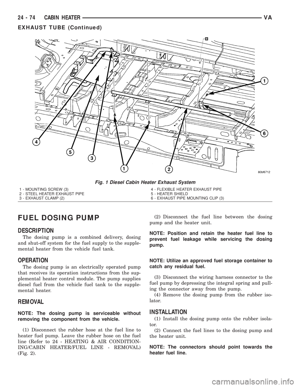
and steel pipe connection (Fig. 1).
(3) Remove the clamp at the flexible pipe connec-
tion and the supplemental heater housing (if
required).
(4) Remove the three screws holding the exhaust
pipe to the body.(5) Remove the steel exhaust pipe from the vehi-
cle.
(6) Remove the flexible exhaust pipe from the
vehicle (if required).INSTALLATION
(1) Install the flexible exhaust pipe to the heater
unit. Tighten mounting clamp securely.
(2) Position the steel exhaust pipe to the flexible
exhaust and install and tighten the mounting clamp
securely.
(3) Install the three exhaust pipe screws, adjust
pipe placement as needed and tighten the screws
securely.
(4) Install the clamp to connect the steel exhaust
pipe to the flexible exhaust pipe and tighten clamp
securely.
(5) Check exhaust pipe exhaust end placement and
make any final adjustments.
(6) Lower the vehicle.
VACABIN HEATER 24 - 73
CABIN HEATER (Continued)
Page 1202 of 1232
FUEL DOSING PUMP
DESCRIPTION
The dosing pump is a combined delivery, dosing
and shut-off system for the fuel supply to the supple-
mental heater from the vehicle fuel tank.
OPERATION
The dosing pump is an electrically operated pump
that receives its operation instructions from the sup-
plemental heater control module. The pump supplies
diesel fuel from the vehicle fuel tank to the supple-
mental heater.
REMOVAL
NOTE: The dosing pump is serviceable without
removing the component from the vehicle.
(1) Disconnect the rubber hose at the fuel line to
heater fuel pump. Leave the rubber hose on the fuel
line (Refer to 24 - HEATING & AIR CONDITION-
ING/CABIN HEATER/FUEL LINE - REMOVAL)
(Fig. 2).(2) Disconnect the fuel line between the dosing
pump and the heater unit.
NOTE: Position and retain the heater fuel line to
prevent fuel leakage while servicing the dosing
pump.
NOTE: Utilize an approved fuel storage container to
catch any residual fuel.
(3) Disconnect the wiring harness connector to the
fuel pump by depressing the integral spring and pull-
ing the connector away from the pump.
(4) Remove the dosing pump from the rubber iso-
lator.INSTALLATION
(1) Install the dosing pump onto the rubber isola-
tor.
(2) Connect the fuel lines to the dosing pump and
the heater unit.
NOTE: The connectors should point towards the
heater fuel line.
Fig. 1 Diesel Cabin Heater Exhaust System
1 - MOUNTING SCREW (3)
2 - STEEL HEATER EXHAUST PIPE
3 - EXHAUST CLAMP (2)4 - FLEXIBLE HEATER EXHAUST PIPE
5 - HEATER SHIELD
6 - EXHAUST PIPE MOUNTING CLIP (3)
24 - 74 CABIN HEATERVA
EXHAUST TUBE (Continued)