Page 267 of 356

265 Practical hints
Where will I find ...?
1Vehicle jack
2Wheel bolt wrench
3Screwdriver
4Interchangeable slot
Screwdriver3 is placed inside the wheel-
bolt wrench handle.Vehicle jack
Please also observe the safety guidelines
in the “Flat tire” section (
�page 284)
when using the jack.
Vehicle with CD-changer*
To access the vehicle tool kit, swing the
CD-changer out of the panel.
1Screw
2CD-changer
�
Turn screw1 counterclockwise.
�
Swing the CD-changer2 out of the
panel.
Warning!
G
The jack is designed exclusively for jacking
up the vehicle at the jack take-up brackets
built into both sides of the vehicle. To help
avoid personal injury, use the jack only to lift
the vehicle during a wheel change. Never
get beneath the vehicle while it is supported
by the jack. Keep hands and feet away from
the area under the lifted vehicle. Always
firmly set parking brake and block wheels
before raising vehicle with jack.
Do not disengage parking brake while the
vehicle is raised. Be certain that the jack is
always vertical (plumb line) when in use, es-
pecially on hills. Always try to use the jack
on level surface.
Make sure that the jack arm is fully seated
in the jack take-up bracket. Always lower
the vehicle onto sufficient capacity jack-
stands before working under the vehicle.
Page 268 of 356

Use the spare wheel only temporarily,
while observing the following restrictions:�
Do not exceed vehicle speed of
50 mph (80 k")
266 Practical hintsWhere will I find ...?Spare wheel (space-saver tire)
Use the spare wheel only temporarily,
while observing the following restrictions:�
Do not exceed vehicle speed of
50 mph (80 km / h).
�
Drive to the nearest repair facility to
have the flat tire repaired or replaced
as appropriate.
�
Do not operate vehicle with more than
one spare wheel mounted.Removing spare wheel
The spare wheel is located behind the rear
bumper.
1Cover
�
Hold left and right side of cover1 and
pull away from bumper.2Screw
3Spare wheel carrier
4Lever
�
Turn screw2 counterclockwise using
the wrench (
�page 265).
Screw2 remains in spare wheel
carrier3.
�
Lift spare wheel carrier slightly and
push lever4 to the right using screw-
driver (
�page 264).
�
Swing spare wheel carrier3 down and
pull it out from under the bumper.
Warning!
G
The dimensions of the spare wheel are dif-
ferent from those of the road wheels. As a
result, the vehicle handling characteristics
change when driving with a mounted spare
wheel.iPlease comply with the instructions for
“Mounting the spare wheel”
(�page 284).
Warning!
G
Exercise care when removing or installing
spare wheel to prevent personal injury.
Page 270 of 356
268 Practical hintsUnlocking / locking in an emergencyUnlocking the vehicle
If you are unable to unlock the driver’s
door using the remote control, open the
door using the folding key.Remote control with folding key
1Release button
�
Press release button1 on the remote
control.
The key folds out.Unlocking the driver’s door
1Unlocking
�
Insert the key into the driver’s door
lock until it stops.
�
Turn the key counterclockwise to
position1.
The driver’s door is unlocked.
iUnlocking the driver’s door with the
folding key will trigger the anti-theft
alarm system.
To cancel the alarm, do one of the
following:�
Press buttonŒ or‹ on the
remote control.
�
Insert the key in the steering lock.
Page 271 of 356
269 Practical hints
Unlocking / locking in an emergency
Locking the vehicle
If you are unable to lock the vehicle with
the remote control, lock it with the folding
key as follows:�
Close the passenger doors and the lift-
gate.
�
Press the upper part of the central
locking switch in the cockpit
(�page 93).
�
Check to see whether the locking
knobs on the passenger doors have
moved down. If necessary push them
down manually.
�
Lock the liftgate if necessary from in-
side (
�page 91).
Except for the driver’s door, the vehicle
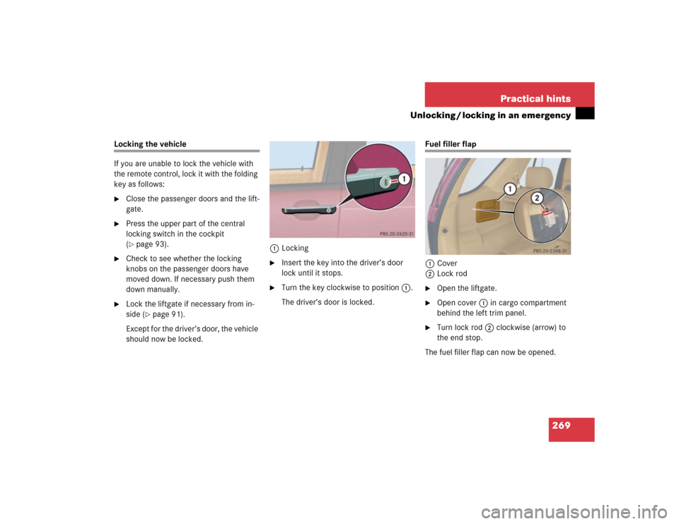
should now be locked.1Locking
�
Insert the key into the driver’s door
lock until it stops.
�
Turn the key clockwise to position1.
The driver’s door is locked.
Fuel filler flap
1Cover
2Lock rod�
Open the liftgate.
�
Open cover1 in cargo compartment
behind the left trim panel.
�
Turn lock rod2 clockwise (arrow) to
the end stop.
The fuel filler flap can now be opened.
Page 273 of 356
271 Practical hints
Opening / closing in an emergency
�Opening / closing in an emergency
Power tilt / sliding sunroof*
You can open or close the tilt / sliding
sunroof manually should an electrical
malfunction occur.
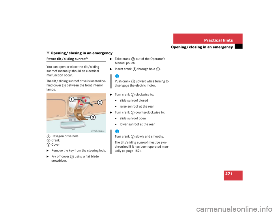
The tilt / sliding sunroof drive is located be-
hind cover3 between the front interior
lamps.
1Hexagon drive hole
2Crank
3Cover�
Remove the key from the steering lock.
�
Pry off cover3 using a flat blade
srewdriver.
�
Take crank2 out of the Operator’s
Manual pouch.
�
Insert crank2 through hole1.
�
Turn crank2 clockwise to:�
slide sunroof closed
�
raise sunroof at the rear
�
Turn crank2 counterclockwise to:�
slide sunroof open
�
lower sunroof at the rear
iPush crank2 upward while turning to
disengage the electric motor.iTurn crank2 slowly and smoothy.
The tilt / sliding sunroof must be syn-
chronized if it has been operated man-
ually (
�page 152).
Page 280 of 356
�
Turn housing cover1")
278 Practical hintsReplacing bulbsHigh beam halogen bulb (vehicles with
halogen bulbs: high beam and high
beam flasher; vehicles with Xenon*
headlamps: high beam flasher only)�
Turn housing cover1 counterclock-
wise and remove it.
�
Pull electrical connector2 off.
�
Unclip the retainer spring on the bulb
socket and take out the bulb.
�
Insert the new bulb so that its socket
locates in the recess of the lamp hous-
ing.
�
Clip on the retainer spring.
�
Plug electrical connector2 onto the
bulb.
�
Align housing cover1 and turn it
clockwise.Parking / standing lamp bulb
�
Turn housing cover1 counterclock-
wise and remove it.
�
Pull out bulb socket3 with the bulb.
�
Press gently onto the bulb and turn
counterclockwise out of bulb
socket3.
�
Press the new bulb gently into bulb
socket3 and turn clockwise until it
engages.
�
Press bulb socket3 back into the
lamp.
�
Align housing cover1 and turn it
clockwise.Turn signal bulb / side marker bulb
1Bulb socket
�
Twist bulb socket1 counterclockwise
and pull out.
�
Push bulb into socket, turn counter-
clockwise and remove.
�
Insert new bulb in socket, push in and
twist clockwise.
�
Reinstall the bulb socket1.
Page 281 of 356
279 Practical hints
Replacing bulbs
Front fog lamp
1Front fog lamp�
Use a suitable object (e.g. screwdriver)
to press on the release lever behind the
front panel.
Front fog lamp1 releases.
�
Pull front fog lamp1 out of the
bumper.2Bulb socket of front fog lamp bulb
3Tabs
�
Turn bulb socket2 with the bulb
counterclockwise and remove it.
�
Insert new bulb socket2 with the bulb
into the lamp and turn it clockwise.
�
Reinstall front fog lamp1 into the
bumper.
Let tabs3 engage in the bumper.
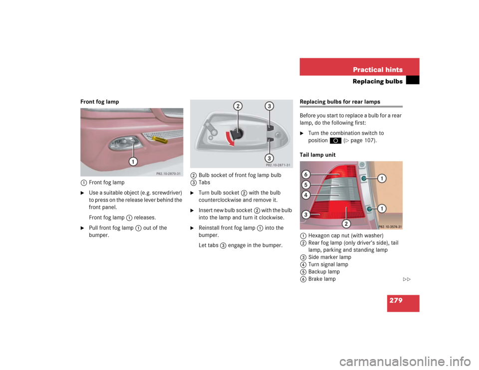
Replacing bulbs for rear lamps
Before you start to replace a bulb for a rear
lamp, do the following first:�
Turn the combination switch to
positionD (
�page 107).
Tail lamp unit
1Hexagon cap nut (with washer)
2Rear fog lamp (only driver’s side), tail
lamp, parking and standing lamp
3Side marker lamp
4Turn signal lamp
5Backup lamp
6Brake lamp
��
Page 282 of 356

280 Practical hintsReplacing bulbs7Tab
8Bulb socket for rear side marker lamp
bulb
�
Open the liftgate.
�
Remove hexagon cap nuts1 with
washers on them.
�
Remove tail lamp unit.
�
Press tabs7 together.
�
Remove the bulb carrier.
�
Press gently onto the respective bulb
and turn counterclockwise out of its
bulb socket.
�
Press the new bulb gently into its bulb
socket and turn clockwise until it en-
gages.
�
Reinstall the bulb carrier.
Let tabs7 engage.
�
Insert the tail lamp unit in the body,
lower edge first.
Let the tail lamp unit engage.
�
Retighten hexagon cap nuts1 with
washers on them.Rear side marker
�
Open the liftgate.
�
Remove hexagon cap nuts1 with
washers on them.
�
Remove tail lamp unit.
�
Turn bulb socket8 with the bulb
counterclockwise and remove it.
�
Pull the bulb out of bulb socket8.
�
Press the new bulb into bulb socket8.
�
Insert bulb socket8 back into the
lamp and turn it clockwise.
�
Insert the tail lamp unit in the body,
lower edge first.
Let the tail lamp unit engage.
�
Retighten hexagon cap nuts1 with
washers on them.
��