Page 158 of 356

156 Controls in detailDriving systemsParktronic* system (Parking assist)
The Parktronic system is an electronic and
designed to assist the driver during park-
ing maneuvers. It visually and audibly indi-
cates the relative distance between the
vehicle and an obstacle.
The Parktronic system is automatically
activated when you switch on the ignition.
The Parktronic system deactivates at
speeds over approximately 10 mph
(15 km / h). At lower speeds the Parktronic
system turns on again.The Parktronic system monitors the sur-
roundings of your vehicle with six sensors
in the front bumper and four sensors in the
rear bumper.
1Sensors located in front bumperWarning!
G
The Parktronic is a supplemental system. It
is not intended to, nor does it replace, the
need for extreme care. The responsibility
during parking and other critical maneuvers
always rests with the driver.
Special attention must be paid to objects
with smooth surfaces or low silhouettes
(e.g. trailer couplings, painted posts, or road
curbs). Such objects may not be detected by
the system and can damage the vehicle.
The operational function of the Parktronic
system can be affected by dirty sensors, es-
pecially at times of snow and ice. See
“Cleaning the Parktronic system sensors”
(�page 243).
Interference caused by other ultrasonic sig-
nals (e.g. working jackhammers, car wash,
or the air brakes of trucks) can cause the
system to send erratic indications, and
should be taken into consideration.
Warning!
G
Make sure that no persons or animals are in
the area in which you are maneuvering. You
could otherwise injure them.
Page 213 of 356

211 Operation
Driving instructions
�
Inspect frame, oil pan, brake hoses,
etc., as well as vehicle underbody for
possible damage.
�
Check tires for possible damage, clean
all exterior lamps, and conduct a brake
test.
�
Check for brush or branches caught in
the undercarriage.
They could increase the possibility of a
fire, as well as cut fuel and / or brake
lines, puncture rubber bellows of the
axles or drive shafts.
�
After continued operation in mud,
sand, water or other dirty conditions
clean the brake discs, wheels, brake
pads and check and clean axle joints.
Trailer towing Trailer hitches
�
Only install a trailer hitch receiver ap-
proved for your vehicle.
For information on availability and in-
stallation, see an authorized
Mercedes-Benz Light Truck Center.
�
The bumpers on your vehicle are not
designed for use with clamp-type hitch-
es.
Do not attach rental hitches or other
bumper-type hitches to them.
�
To reduce the possibility of damage, re-
move the hitch ball adaptor from the
receiver when not in use.
Warning!
G
Failure to use proper equipment and driving
technique can result in a loss of vehicle con-
trol when towing a trailer.
Improper towing or failure to follow the in-
structions contained in this guide can result
in serious injury. Follow the guidelines be-
low carefully to assure safe trailer operation.
Ask an authorized Mercedes-Benz Light
Truck Center should you require an explana-
tion of information contained in this guide.
Page 215 of 356

213 Operation
Driving instructions
Checking weights of vehicle and trailer�
To assure that the tow vehicle and trail-
er are in compliance with the maximum
permissible weight limits have the load-
ed rig (tow vehicle including driver, pas-
sengers and cargo, trailer fully loaded)
weighed on a commercial scale.
�
Check the vehicle’s front and rear
Gross Axle Weight (GAW), the GTW and
TW.
The values as measured must not be
exceeded, according to the weight list-
ed under “Vehicle and trailer weight
and ratings”.Attaching a trailer
Observe maximum permitted trailer
dimensions (width and length).
Most states and all Canadian provinces
require
�
safety chains between your tow vehicle
and the trailer.
The chains should be crisscrossed un-
der the trailer tongue. They must be at-
tached to the hitch receiver, and not to
the vehicle’s bumper or axle.
Make sure to leave enough slack in the
chains to permit turning corners.
�
a separate brake system at various
trailer weights.
�
a break-away switch on trailers with a
separate brake system.
The switch activates the trailer brakes
in the possible event that the trailer
might separate from the tow vehicle.
!Do not connect a trailer brake system
(if trailer is so equipped) directly to the
vehicle’s hydraulic brake system, as
your vehicle is equipped with antilock
brakes. If you do, neither the vehicle’s
brakes nor the trailer’s brakes will func-
tion properly.iThe provided vehicle electrical wiring
harness for trailer towing has a brake
signal wire (color orange) for hook-up
to a brake controller.
You should consider using a trailer
sway control system. For further infor-
mation see an authorized
Mercedes-Benz Light Truck Center.
Page 268 of 356

266 Practical hintsWhere will I find ...?Spare wheel (space-saver tire)
Use the spare wheel only temporarily,
while observing the following restrictions:�
Do not exceed vehicle speed of
50 mph (80 km / h).
�
Drive to the nearest repair facility to
have the flat tire repaired or replaced
as appropriate.
�
Do not operate vehicle with more than
one spare wheel mounted.Removing spare wheel
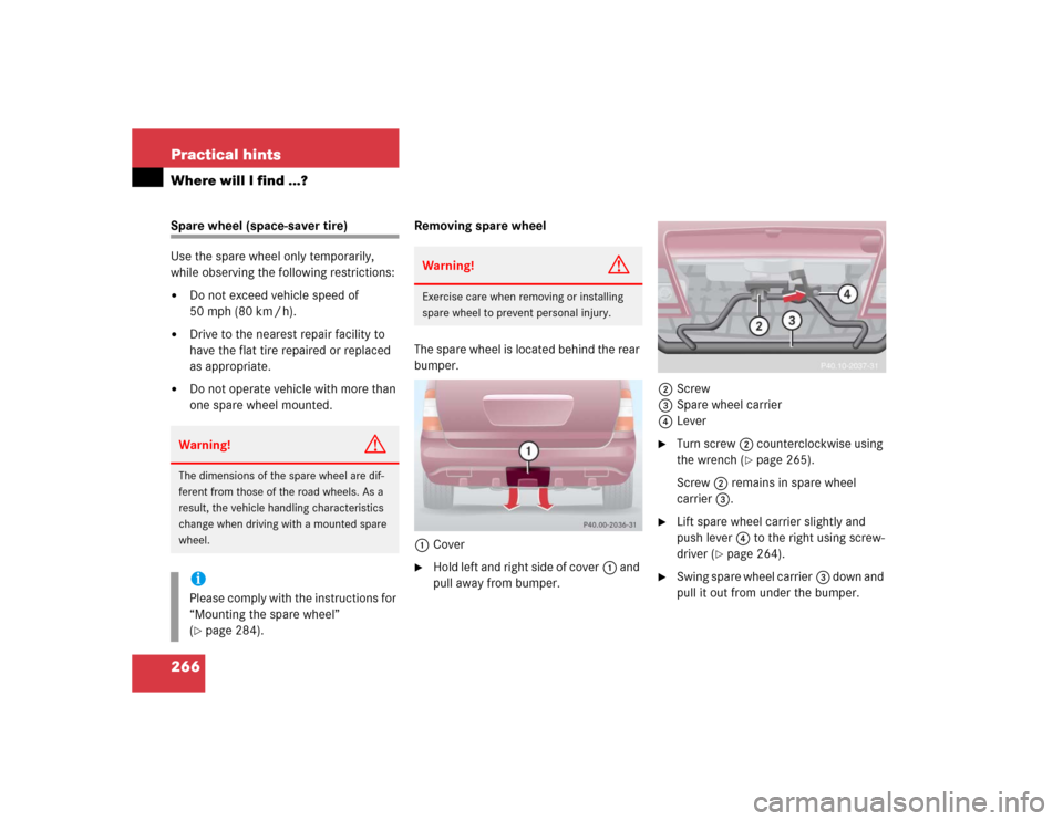
The spare wheel is located behind the rear
bumper.
1Cover
�
Hold left and right side of cover1 and
pull away from bumper.2Screw
3Spare wheel carrier
4Lever
�
Turn screw2 counterclockwise using
the wrench (
�page 265).
Screw2 remains in spare wheel
carrier3.
�
Lift spare wheel carrier slightly and
push lever4 to the right using screw-
driver (
�page 264).
�
Swing spare wheel carrier3 down and
pull it out from under the bumper.
Warning!
G
The dimensions of the spare wheel are dif-
ferent from those of the road wheels. As a
result, the vehicle handling characteristics
change when driving with a mounted spare
wheel.iPlease comply with the instructions for
“Mounting the spare wheel”
(�page 284).
Warning!
G
Exercise care when removing or installing
spare wheel to prevent personal injury.
Page 269 of 356
267 Practical hints
Where will I find ...?
5Bayonet lock�
Turn the bayonet lock5 90° to the
left.
�
Pull off bayonet lock5.
�
Remove the spare wheel cover and the
spare wheel.
�
Store bayonet lock5 and spare wheel
cover in cargo compartment.
�
Replace the spare wheel carrier and se-
cure it in place.
�
Install cover1 to the bumper.
!When storing the space-saver spare
wheel in its holder, secure it using the
bayonet lock.
Page 281 of 356
279 Practical hints
Replacing bulbs
Front fog lamp
1Front fog lamp�
Use a suitable object (e.g. screwdriver)
to press on the release lever behind the
front panel.
Front fog lamp1 releases.
�
Pull front fog lamp1 out of the
bumper.2Bulb socket of front fog lamp bulb
3Tabs
�
Turn bulb socket2 with the bulb
counterclockwise and remove it.
�
Insert new bulb socket2 with the bulb
into the lamp and turn it clockwise.
�
Reinstall front fog lamp1 into the
bumper.
Let tabs3 engage in the bumper.
Replacing bulbs for rear lamps
Before you start to replace a bulb for a rear
lamp, do the following first:�
Turn the combination switch to
positionD (
�page 107).
Tail lamp unit
1Hexagon cap nut (with washer)
2Rear fog lamp (only driver’s side), tail
lamp, parking and standing lamp
3Side marker lamp
4Turn signal lamp
5Backup lamp
6Brake lamp
��
Page 297 of 356

295 Practical hints
Towing the vehicle
Front towing eye
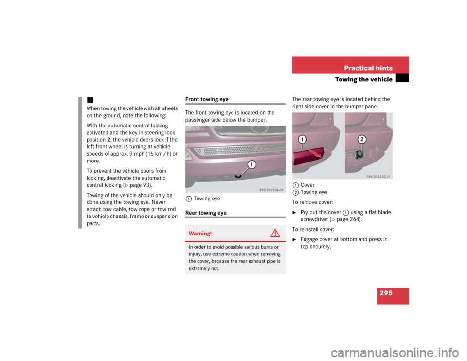
The front towing eye is located on the
passenger side below the bumper.
1Towing eyeRear towing eyeThe rear towing eye is located behind the
right side cover in the bumper panel.
1Cover
2Towing eye
To remove cover:
�
Pry out the cover1 using a flat blade
screwdriver (
�page 264).
To reinstall cover:
�
Engage cover at bottom and press in
top securely.
!When towing the vehicle with all wheels
on the ground, note the following:
With the automatic central locking
activated and the key in steering lock
position2, the vehicle doors lock if the
left front wheel is turning at vehicle
speeds of approx. 9 mph (15 km / h) or
more.
To prevent the vehicle doors from
locking, deactivate the automatic
central locking (
�page 93).
Towing of the vehicle should only be
done using the towing eye. Never
attach tow cable, tow rope or tow rod
to vehicle chassis, frame or suspension
parts.
Warning!
G
In order to avoid possible serious burns or
injury, use extreme caution when removing
the cover, because the rear exhaust pipe is
extremely hot.