Page 503 of 969
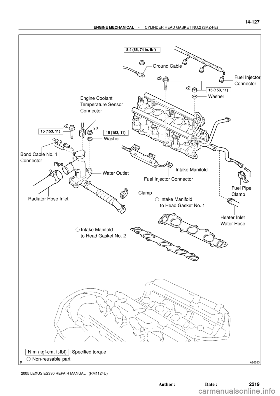
A86583� Non-reusable part
: Specified torqueN´m (kgf´cm, ft´lbf)� Intake Manifold
to Head Gasket No. 2� Intake Manifold
to Head Gasket No. 1
Radiator Hose InletWater Outlet
Heater Inlet
Water Hose Intake Manifold Ground Cable
Washer
8.4 (86, 74 in.Vlbf)
x2x9
x2
Washer
15 (153, 11)
15 (153, 11)
Fuel Pipe
Clamp
15 (153, 11)
Fuel Injector
Connector
Clamp
Fuel Injector Connector
x2
Engine Coolant
Temperature Sensor
Connector
Bond Cable No. 1
Connector
Pipe
- ENGINE MECHANICALCYLINDER HEAD GASKET NO.2 (3MZ-FE)
14-127
2219 Author�: Date�:
2005 LEXUS ES330 REPAIR MANUAL (RM1124U)
Page 509 of 969

14-133
2225 Author�: Date�:
2005 LEXUS ES330 REPAIR MANUAL (RM1124U)
REPLACEMENT
1. DISCHARGE FUEL SYSTEM PRESSURE (See page 11-")
141JJ-01
A86574
- ENGINE MECHANICALCYLINDER HEAD GASKET NO.2 (3MZ-FE)
14-133
2225 Author�: Date�:
2005 LEXUS ES330 REPAIR MANUAL (RM1124U)
REPLACEMENT
1. DISCHARGE FUEL SYSTEM PRESSURE (See page 11-1)
2. DISCONNECT BATTERY NEGATIVE TERMINAL
3. DRAIN ENGINE COOLANT (See page 16-9)
4. DRAIN ENGINE OIL (See page 17-20)
5. REMOVE FRONT WHEEL RH
6. REMOVE RADIATOR LOWER AIR DEFLECTOR (See page 19-5)
7. REMOVE FRONT SUSPENSION UPPER BRACE CENTER (W/O TEMS) (See page 10-1 1)
8. REMOVE V-BANK COVER SUB-ASSY (See page 10-1 1)
9. REMOVE AIR CLEANER INLET ASSY (See page 19-5)
10. REMOVE AIR CLEANER CAP SUB-ASSY (See page 10-1 1)
11. REMOVE AIR CLEANER CASE (See page 19-5)
12. REMOVE EMISSION CONTROL VALVE SET (See page 11-13)
13. REMOVE INTAKE AIR SURGE TANK (See page 11-13)
14. REMOVE INTAKE MANIFOLD (See page 10-16)
15. REMOVE WATER OUTLET (See page 10-16)
16. REMOVE FRONT FENDER APRON SEAL RH
17. REMOVE V (COOLER COMPRESSOR TO CRANKSHAFT PULLEY) BELT NO.1
(See page 14-5)
18. REMOVE VANE PUMP V BELT (See page 14-5)
19. REMOVE ENGINE MOVING CONTROL ROD (See page 14-79)
20. REMOVE ENGINE MOUNTING STAY NO.2 RH (See page 14-79)
21. REMOVE GENERATOR BRACKET NO.2 (See page 14-79)
22. REMOVE CRANKSHAFT PULLEY (See page 14-79)
SST 09213-54015 (91651-60855), 09330-00021, 09950-50013 (09951-05010, 09952-05010,
09953-05020, 09954-05031)
23. REMOVE TIMING BELT NO.1 COVER
24. REMOVE TIMING BELT NO.2 COVER (See page 14-79)
25. REMOVE ENGINE MOUNTING BRACKET RH (See page 14-79)
26. REMOVE TIMING BELT GUIDE NO.2
27. REMOVE TIMING BELT (See page 14-79)
28. REMOVE TIMING BELT IDLER SUB-ASSY NO.2
29. REMOVE CAMSHAFT TIMING PULLEY (See page 14-93)
SST 09960-10010 (09962-01000, 09963-01000), 09249-63010
30. REMOVE TIMING BELT NO.3 COVER (See page 14-93)
31. REMOVE MANIFOLD STAY NO.2 (See page 14-29)
32. SEPARATE EXHAUST PIPE ASSY FRONT (See page 15-2)
33. REMOVE OIL LEVEL GAGE GUIDE
(a) Remove the bolt which secures the oil level gage guide
from the cylinder head LH.
(b) Pull out the oil level gage guide and oil level gage together
from the cylinder block.
(c) Remove the O-ring from the oil level gage guide.
Page 565 of 969

(b)
Deep Socket
Wrench 19
10-8- ENGINE CONTROL SYSTEMENGINE COOLANT TEMPERATURE
SENSOR (3MZ-FE)
2013 Author�: Date�:
2005 LEXUS ES330 REPAIR MANUAL (RM1124U)
ENGINE COOLANT TEMP")
100J3-02
A86247
(a)
(b)
Deep Socket
Wrench 19
10-8- ENGINE CONTROL SYSTEMENGINE COOLANT TEMPERATURE
SENSOR (3MZ-FE)
2013 Author�: Date�:
2005 LEXUS ES330 REPAIR MANUAL (RM1124U)
ENGINE COOLANT TEMPERATURE SENSOR (3MZ-FE)
REPLACEMENT
1. DISCONNECT ENGINE WIRE NO. 3 (BATTERY NEGATIVE TERMINAL)
2. REMOVE RADIATOR LOWER AIR DEFLECTOR (See page 19-5)
3. DRAIN ENGINE COOLANT (See page 16-9)
4. REMOVE ENGINE COOLANT TEMPERATURE
SENSOR
(a) Disconnect the engine coolant temperature sensor con-
nector.
(b) Using a deep socket wrench 19, remove the engine cool-
ant temperature sensor and gasket.
5. INSTALL ENGINE COOLANT TEMPERATURE SENSOR
(a) Using a deep socket wrench 19, install a new gasket and the engine coolant temperature sensor.
Torque: 20 NVm (200 kgfVcm, 14 ftVlbf)
(b) Connect the engine coolant temperature sensor connector.
6. CONNECT ENGINE WIRE NO. 3 (BATTERY NEGATIVE TERMINAL)
Torque: 5.4 NVm (55 kgfVcm, 48 in.Vlbf)
7. ADD ENGINE COOLANT (See page 16-9)
8. CHECK FOR ENGINE COOLANT LEAKS (See page 16-1)
9. INSTALL RADIATOR LOWER AIR DEFLECTOR
10. SYSTEM INITIALIZATION (See page 19-15)
Page 568 of 969
(a)
(a)
(b) 2 Retainers
Socket Hexagon
Wrench 5
A86252
(a)
(b)
(d)
(e)
(b)
(b)
(b)
(c)
(d)
(e)
(f)
A86253
(a)
(c) (b)
- ENGINE CONTROL SYSTEMTHROTTLE BODY ASSY (3MZ-FE)
10-1")
100J5-01
A86250
A86251
(a)(a)
(a)
(b) 2 Retainers
Socket Hexagon
Wrench 5
A86252
(a)
(b)
(d)
(e)
(b)
(b)
(b)
(c)
(d)
(e)
(f)
A86253
(a)
(c) (b)
- ENGINE CONTROL SYSTEMTHROTTLE BODY ASSY (3MZ-FE)
10-1 1
2016 Author�: Date�:
2005 LEXUS ES330 REPAIR MANUAL (RM1124U)
REPLACEMENT
1. DISCONNECT ENGINE WIRE NO. 3 (BATTERY NEGATIVE TERMINAL)
2. REMOVE RADIATOR LOWER AIR DEFLECTOR (See page 19-5)
3. DRAIN ENGINE COOLANT (See page 19-5)
4. REMOVE FRONT SUSPENSION UPPER BRACE
CENTER (W/O TEMS)
(a) Remove the 4 nuts, then remove the front suspension up-
per brace center and 4 spacers.
(b) Temporarily tighten the 4 nuts.
5. REMOVE V-BANK COVER SUB-ASSY
(a) Using a socket hexagon wrench 5, remove the 3 nuts.
(b) Unfasten the 2 retainers, then remove the V-bank cover.
6. REMOVE AIR CLEANER CAP SUB-ASSY
(a) Disconnect the mass air flow meter connector.
(b) Disconnect the 4 vacuum hoses.
(c) Disconnect the ventilation hose No. 2.
(d) Disconnect the fuel vapor feed hose from the 2 hose
clamps.
(e) Loosen the 2 air cleaner cap bolts.
(f) Loosen the air cleaner hose clamp bolt, then remove the
air cleaner cap.
(g) Remove the air cleaner filter element.
7. REMOVE THROTTLE BODY ASSY
(a) Disconnect the throttle motor connector.
(b) Disconnect the water by-pass hose No. 2.
(c) Disconnect the water by-pass hose No. 3.
Page 569 of 969

(d)
(d)
(d) 10-12
- ENGINE CONTROL SYSTEMTHROTTLE BODY ASSY (3MZ-FE)
2017 Author�: Date�:
2005 LEXUS ES330 REPAIR MANUAL (RM1124U)
(d) Remove the 4 bolts, then remove the throttle body.
(")
A86254
(d)
(d)
(d)
(d) 10-12
- ENGINE CONTROL SYSTEMTHROTTLE BODY ASSY (3MZ-FE)
2017 Author�: Date�:
2005 LEXUS ES330 REPAIR MANUAL (RM1124U)
(d) Remove the 4 bolts, then remove the throttle body.
(e) Remove the gasket from the intake air connector.
8. INSTALL THROTTLE BODY ASSY
(a) Install a new gasket to the intake air connector.
(b) Install the throttle body with the 4 bolts.
Torque: 11 NVm (112 kgfVcm, 8 ftVlbf)
(c) Connect the water by-pass hose No. 3.
(d) Connect the water by-pass hose No. 2.
(e) Connect the throttle motor connector.
9. INSTALL AIR CLEANER CAP SUB-ASSY
Torque: 5.0 NVm (51 kgfVcm, 44 in.Vlbf)
10. CHECK CONNECTION OF VACUUM HOSE (See page 14-29)
11. CONNECT ENGINE WIRE NO. 3 (BATTERY NEGATIVE TERMINAL)
Torque: 5.4 NVm (55 kgfVcm, 48 in.Vlbf)
12. ADD ENGINE COOLANT (See page 16-9)
13. CHECK FOR ENGINE COOLANT LEAKS (See page 16-1)
14. INSTALL V-BANK COVER SUB-ASSY
(a) Fit the 2 retainers, then install the V-bank cover.
(b) Using a socket hexagon wrench 5, tighten the 3 nuts.
Torque: 7.9 NVm (81 kgfVcm, 70 in.Vlbf)
15. INSTALL FRONT SUSPENSION UPPER BRACE CENTER (W/O TEMS)
Torque: 80 NVm (816 kgfVcm, 59 ftVlbf)
16. INSTALL RADIATOR LOWER AIR DEFLECTOR
17. SYSTEM INITIALIZATION (See page 19-15)
Page 572 of 969
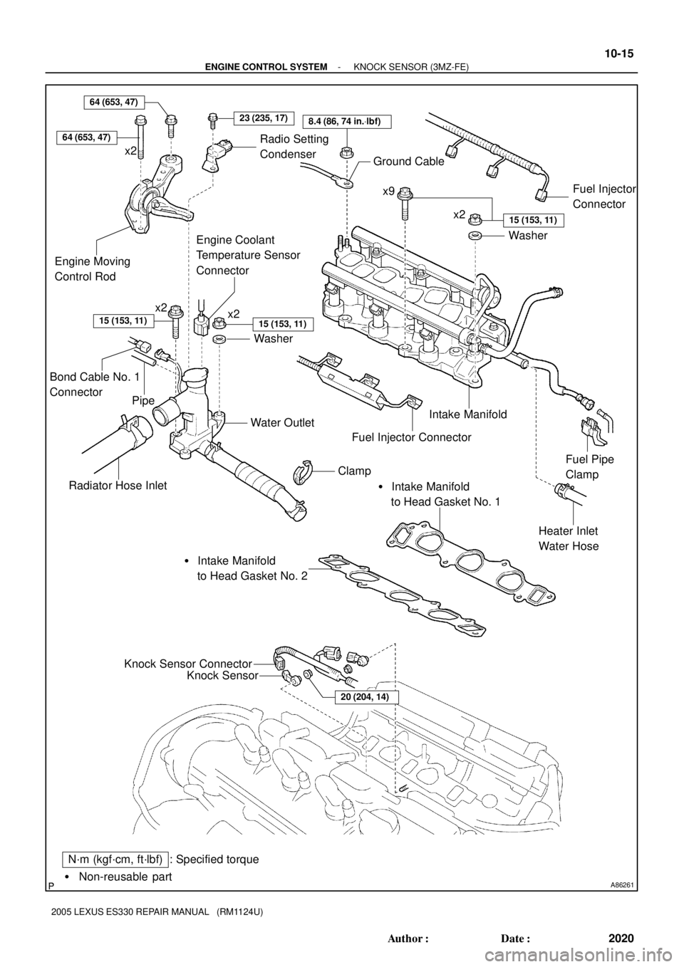
A86261� Non-reusable part
: Specified torqueN´m (kgf´cm, ft´lbf)Knock Sensor
Knock Sensor Connector
20 (204, 14)
� Intake Manifold
to Head Gasket No. 2� Intake Manifold
to Head Gasket No. 1
Radiator Hose InletWater Outlet
Heater Inlet
Water Hose Intake Manifold Ground Cable
Washer
8.4 (86, 74 in.Vlbf)
x2x9
x2
Washer
15 (153, 11)
15 (153, 11)
Fuel Pipe
Clamp
Engine Moving
Control Rod
23 (235, 17)
15 (153, 11)
x2
Fuel Injector
Connector
Clamp
Fuel Injector Connector
64 (653, 47)
x2
Engine Coolant
Temperature Sensor
Connector
Radio Setting
Condenser
64 (653, 47)
Bond Cable No. 1
Connector
Pipe
- ENGINE CONTROL SYSTEMKNOCK SENSOR (3MZ-FE)
10-15
2020 Author�: Date�:
2005 LEXUS ES330 REPAIR MANUAL (RM1124U)
Page 574 of 969
A86265
(c)
(d)
(d)
(d)
(d)
(d)(d)
A862661 2
3 4
75
68
9 10
11
A86267
(a)
(b)
(c)
- ENGINE CONTROL SYSTEMKNOCK SENSOR (3MZ-FE)
10-17
2022 Author�: Date�:
2005 LEXUS ES330 REPAIR MANUAL (RM1124U)
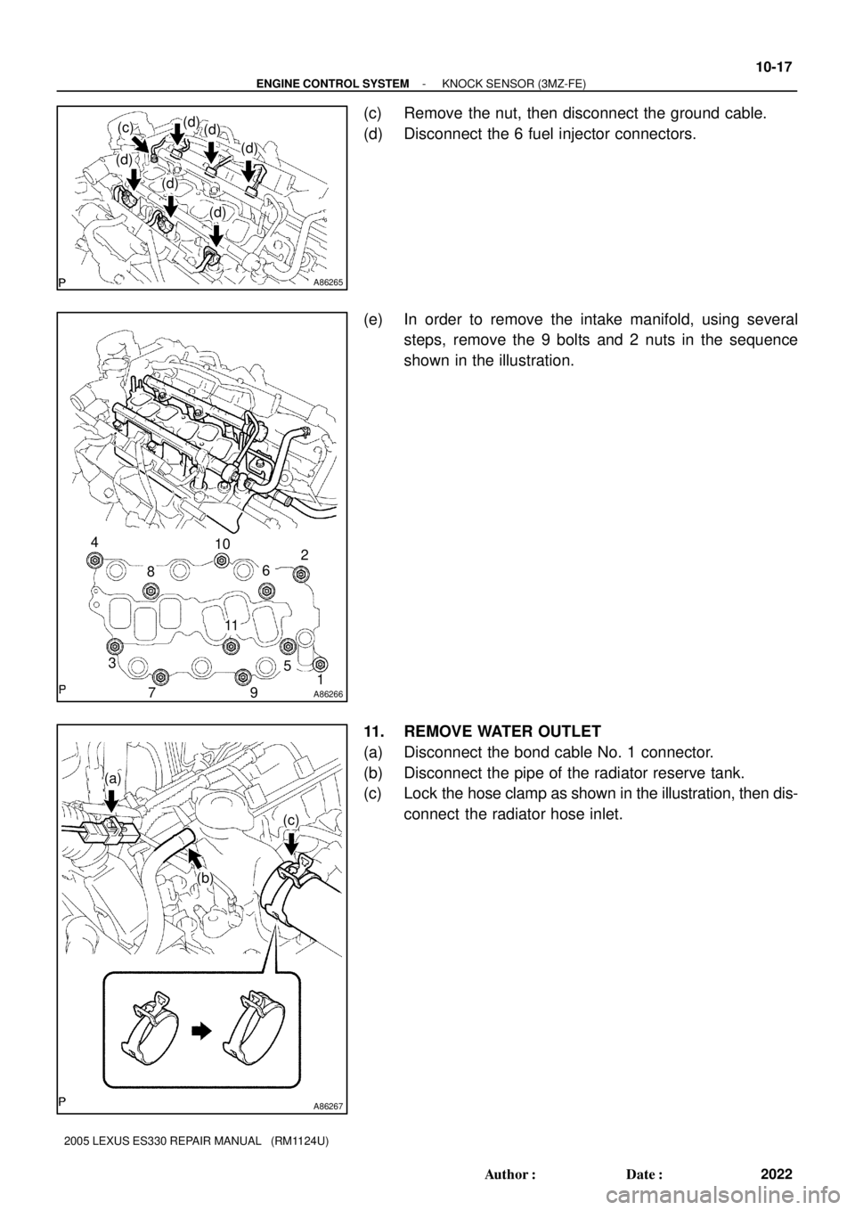
(c) Remove the nut, then disconnect the ground cable.
(d) Disconnect the 6 fuel injector connectors.
(e) In order to remove the intake manifold, using several
steps, remove the 9 bolts and 2 nuts in the sequence
shown in the illustration.
11. REMOVE WATER OUTLET
(a) Disconnect the bond cable No. 1 connector.
(b) Disconnect the pipe of the radiator reserve tank.
(c) Lock the hose clamp as shown in the illustration, then dis-
connect the radiator hose inlet.
Page 575 of 969

(e)
(f)
(f)
(f)
(f)
(g)
A79749
(a)
(b)
(a)
(b)
A79750
Upper
Engine
Front0 to 5� 10-18
- ENGINE CONTROL SYSTEMKNOCK SENSOR (3MZ-FE)
2023 Author�: Date�:
2005 LEXUS ES330 REPAIR MANUAL (RM")
A86268
(d)
(e)
(f)
(f)
(f)
(f)
(g)
A79749
(a)
(b)
(a)
(b)
A79750
Upper
Engine
Front0 to 5� 10-18
- ENGINE CONTROL SYSTEMKNOCK SENSOR (3MZ-FE)
2023 Author�: Date�:
2005 LEXUS ES330 REPAIR MANUAL (RM1124U)
(d) Disconnect the engine coolant temperature sensor con-
nector.
(e) Remove the clamp.
(f) Remove the 2 bolts, 2 nuts and 2 washers.
(g) Lock the hose clamp as shown in the illustration. Then re-
move the water outlet together with water by-pass hose
No. 1.
(h) Remove the 2 gaskets from the 2 cylinder heads.
12. REMOVE KNOCK SENSOR
(a) Disconnect the 2 knock sensor connectors.
(b) Remove the 2 nuts, then remove the 2 knock sensors.
13. INSTALL KNOCK SENSOR
(a) Install the 2 knock sensors with the 2 nuts as shown in the
illustration.
Torque: 20 NVm (204 kgfVcm, 14 ftVlbf)
(b) Connect the 2 knock sensor connectors.
14. INSTALL WATER OUTLET
(a) Install 2 new gaskets to the 2 cylinder heads.
(b) Install the water outlet together with water by-pass hose No. 1, then unlock the hose clamp.
(c) Tighten the 2 bolts, 2 nuts and 2 washers.
Torque: 15 NVm (153 kgfVcm, 11 ftVlbf)
(d) Install the clamp.
(e) Connect the engine coolant temperature sensor connector.
(f) Connect the bond cable No. 3 connector.
(g) Connect the pipe of the radiator reserve tank.
(h) Connect the radiator hose inlet, then unlock the hose clamp.