Page 267 of 969

F41707
F09717
R12236
(A) 32-22
- BRAKEBRAKE MASTER CYLINDER SUB-ASSY
2456 Author�: Date�:
2005 LEXUS ES330 REPAIR MANUAL (RM1124U)
(d) Push in the piston and remove the piston stop")
C69097
R12236
(A)
F41707
F09717
R12236
(A) 32-22
- BRAKEBRAKE MASTER CYLINDER SUB-ASSY
2456 Author�: Date�:
2005 LEXUS ES330 REPAIR MANUAL (RM1124U)
(d) Push in the piston and remove the piston stopper bolt and
gasket.
(e) Remove the No.1 piston sub-assy, pulling straight out not
at an angle.
NOTICE:
If pulled out at an angle, there is a possibility that the cylin-
der bore could be damaged.
(f) Place a waste cloth and 2 wooden blocks on the work
table and lightly edges until the No.2 piston sub-assy
drops out of the cylinder.
HINT:
Make sure the distance (A) from the rag the top of the blocks
is at least 100 mm (3.94 in.).
NOTICE:
If pulled out at an angle, there is a possibility that the cylin-
der bore could be damaged.
9. REMOVE BRAKE MASTER CYLINDER KIT (W/ VSC)
(a) Place master cylinder in vise.
(b) Remove the O-ring.
(c) Push in the piston and remove the snap ring with snap
ring pliers.
NOTICE:
If pulled out at an angle, there is a possibility that the cylin-
der bore could be damaged.
(d) Push in the piston with a screwdriver, and remove the
straight pin by turning over the cylinder body.
HINT:
Tape the screwdriver tip before use.
(e) Remove the No.1 piston sub-assy, pulling straight out not
at an angle.
NOTICE:
If pulled out at an angle, there is a possibility that the cylin-
der bore could be damaged.
(f) Place a waste cloth and 2 wooden blocks on the work
table and lightly edges until the No.2 piston sub-assy
drops out of the cylinder.
HINT:
Make sure the distance (A) from the rag the top of the blocks
is at least 100 mm (3.94 in.).
NOTICE:
If pulled out at an angle, there is a possibility that the cylin-
der bore could be damaged.
Page 268 of 969

10. INSPECT MASTER CYLINDER BODY
(a) Check the cylinder bore for rust or scori")
C69097
F40004
- BRAKEBRAKE MASTER CYLINDER SUB-ASSY
32-23
2457 Author�: Date�:
2005 LEXUS ES330 REPAIR MANUAL (RM1124U)
10. INSPECT MASTER CYLINDER BODY
(a) Check the cylinder bore for rust or scoring.
11. INSTALL BRAKE MASTER CYLINDER KIT (W/O VSC)
(a) Place master cylinder in vise.
(b) Apply the lithium soap base glycol grease on new No.1
and No.2 piston sub-assy.
(c) Install the No.2 and No.1 piston sub-assy.
NOTICE:
�If the piston is inserted at an angle, there is a possibil-
ity that the cylinder bore could be damaged.
�Be careful not to damage the rubber lips on the pis-
tons.
(d) Push in the piston and install a new gasket and a new pis-
ton stopper bolt.
Torque: 10 NVm (100 kgfVcm, 7 ftVlbf)
(e) Push in the piston and install the snap ring with snap ring
pliers.
(f) Apply the lithium soap base glycol grease on a new O-
ring and install the O-ring to the master cylinder.
12. INSTALL BRAKE MASTER CYLINDER KIT (W/ VSC)
(a) Place master cylinder in vise.
(b) Apply the lithium soap base glycol grease on new No.1
and No.2 piston sub-assy.
(c) Install the No.2 and No.1 piston sub-assy.
NOTICE:
�If the piston is inserted at an angle, there is a possibil-
ity that the cylinder bore could be damaged.
�Be careful not to damage the rubber lips on the pis-
tons.
Page 272 of 969
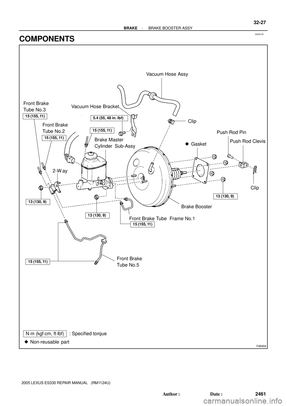
320DZ-05
F46404
Vacuum Hose Assy
Clip
Brake Master
Cylinder Sub-AssyGasket �Push Rod Pin
Push Rod Clevis
Clip
Brake Booster
Front Brake
Tube No.5Front Brake Tube Frame No.1
� Non-reusable part
NVm (kgfVcm, ftVlbf): Specified torque
15 (155, 11)
13 (130, 9)
5.4 (55, 48 in.Vlbf)
13 (130, 9)
15 (155, 11)
13 (130, 9)
Vacuum Hose Bracket
15 (155, 11)
2-W ay
15 (155, 11)
Front Brake
Tube No.2
15 (155, 11)
Front Brake
Tube No.3
- BRAKEBRAKE BOOSTER ASSY
32-27
2461 Author�: Date�:
2005 LEXUS ES330 REPAIR MANUAL (RM1124U)
COMPONENTS
Page 274 of 969

13. REMOVE BRAKE BOOSTER GASKET
14. INSTALL BRAKE BOOSTER GASKET
(a) Install a new")
BR3753
F40996
F40995
- BRAKEBRAKE BOOSTER ASSY
32-29
2463 Author�: Date�:
2005 LEXUS ES330 REPAIR MANUAL (RM1124U)
13. REMOVE BRAKE BOOSTER GASKET
14. INSTALL BRAKE BOOSTER GASKET
(a) Install a new brake booster gasket to the brake booster.
15. INSTALL BRAKE BOOSTER ASSY
(a) Install the brake booster with the 4 nuts.
Torque: 13 NVm (130 kgfVcm, 9 ftVlbf)
16. INSTALL FRONT BRAKE TUBE NO.5
(a) Using SST and install the front brake tube No.5.
Torque: 15 NVm (155 kgfVcm, 11 ftVlbf)
SST 09023-00101
17. INSTALL BRAKE MASTER CYLINDER PUSH ROD CLEVIS
(a) Install the push rod clevis and lock nut.
18. INSTALL PUSH ROD PIN
(a) Install the push rod pin and clip.
HINT:
Apply the lithium soap base glycol grease to the part indicate by arrow (see page 32-27).
19. INSTALL BRAKE PEDAL RETURN SPRING
20. INSTALL INSTRUMENT PANEL INSERT SUB-ASSY LOWER LH (SEE PAGE 71-1 1)
21. INSTALL INSTRUMENT PANEL SUB-ASSY UPPER (SEE PAGE 71-1 1)
22. INSTALL FRONT DOOR SCUFF PLATE LH (SEE PAGE 71-1 1)
23. INSTALL VACUUM HOSE ASSY
(a) Install the vacuum hose and vacuum hose bracket to the
body with a bolt.
Torque: 5.4 NVm (55 kgfVcm, 48 in.Vlbf)
(b) Connect the vacuum hose to the brake booster with the
clip.
24. INSPECT AND ADJUST BRAKE BOOSTER PUSH ROD (SEE PAGE 32-21)
SST 09737-00013, 09737-00020
25. INSTALL BRAKE MASTER CYLINDER SUB-ASSY (SEE PAGE 32-21)
SST 09023-00101
26. FILL RESERVOIR WITH BRAKE FLUID
Page 276 of 969
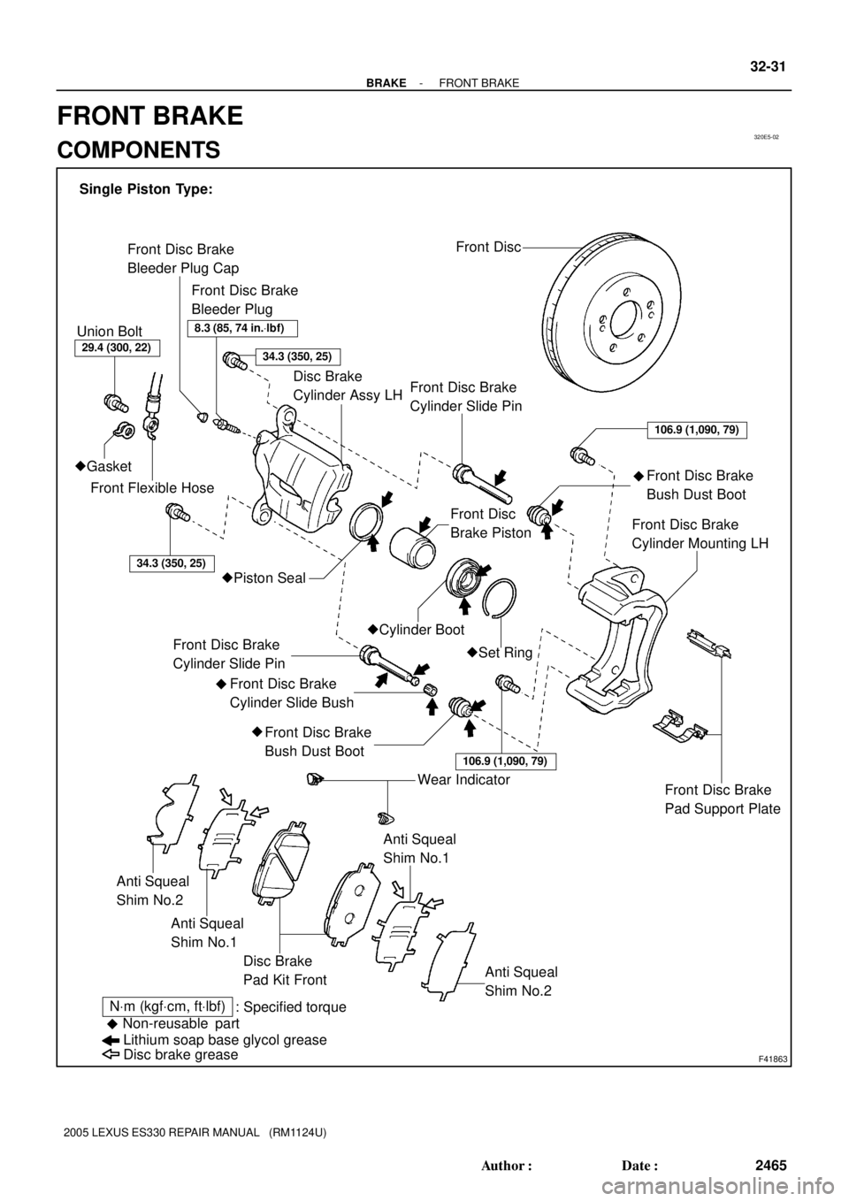
320E5-02
F41863
Front Disc
Front Disc Brake
Bleeder Plug
Front Flexible Hose Union Bolt
�Gasket
Front Disc Brake
Bleeder Plug Cap
Disc Brake
Cylinder Assy LH
�Set Ring
�Cylinder BootFront Disc
Brake Piston
�Piston Seal
Front Disc Brake
Cylinder Slide Pin
Front Disc Brake
Cylinder Slide Bush
Front Disc Brake
Bush Dust Boot
Front Disc Brake
Bush Dust Boot
Front Disc Brake
Cylinder Slide Pin
Front Disc Brake
Cylinder Mounting LH
Front Disc Brake
Pad Support Plate
Disc brake grease Lithium soap base glycol grease
Non-reusable part
�
NVm (kgfVcm, ftVlbf)
: Specified torque Single Piston Type:
�
�
�
Anti Squeal
Shim No.1
Disc Brake
Pad Kit Front Anti Squeal
Shim No.1
Anti Squeal
Shim No.2
Anti Squeal
Shim No.2
Wear Indicator
8.3 (85, 74 in.Vlbf)
29.4 (300, 22)34.3 (350, 25)
34.3 (350, 25)
106.9 (1,090, 79)
106.9 (1,090, 79)
- BRAKEFRONT BRAKE
32-31
2465 Author�: Date�:
2005 LEXUS ES330 REPAIR MANUAL (RM1124U)
FRONT BRAKE
COMPONENTS
Page 277 of 969
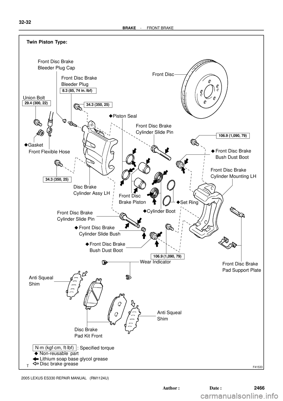
F41533Disc brake grease Lithium soap base glycol grease
Non-reusable part
�
NVm (kgfVcm, ftVlbf)
: Specified torque Front Disc Brake
Bleeder Plug
Front Flexible Hose Union Bolt
�Gasket
Front Disc Brake
Bleeder Plug Cap
Front Disc Brake
Cylinder Slide Pin
Front Disc Brake
Cylinder Slide Bush
Front Disc Brake
Bush Dust Boot
Front Disc Brake
Bush Dust Boot
Front Disc Brake
Cylinder Slide Pin
Front Disc Brake
Cylinder Mounting LH
Front Disc Brake
Pad Support Plate
Front Disc
Anti Squeal
Shim
Disc Brake
Pad Kit Front
Twin Piston Type:
�Set Ring
�Cylinder Boot Front Disc
Brake Piston
�Piston Seal
��
� Disc Brake
Cylinder Assy LH
Anti Squeal
ShimWear Indicator
106.9 (1,090, 79)
106.9 (1,090, 79)
34.3 (350, 25)
8.3 (85, 74 in.Vlbf)
29.4 (300, 22)
34.3 (350, 25)
32-32
- BRAKEFRONT BRAKE
2466 Author�: Date�:
2005 LEXUS ES330 REPAIR MANUAL (RM1124U)
Page 278 of 969

OVERHAUL
HINT:
Overhaul the RH side by the same procedures with LH side.
1. REMOV")
320E6-04
F41534
F41535
F41536
- BRAKEFRONT BRAKE
32-33
2467 Author�: Date�:
2005 LEXUS ES330 REPAIR MANUAL (RM1124U)
OVERHAUL
HINT:
Overhaul the RH side by the same procedures with LH side.
1. REMOVE FRONT WHEEL
2. DRAIN BRAKE FLUID
NOTICE:
Wash the brake fluid off immediately if it comes into contact with any painted surfaces.
3. DISCONNECT FRONT FLEXIBLE HOSE
(a) Remove the union bolt and a gasket from the disc brake cylinder, then disconnect the flexible hose
from the disc brake cylinder.
4. REMOVE DISC BRAKE CYLINDER ASSY LH
(a) Remove the 2 bolts and disc brake cylinder.
5. REMOVE DISC BRAKE PAD KIT FRONT (PAD ONLY)
(a) Remove the 2 brake pads with anti
squeal shims.
6. REMOVE ANTI SQUEAL SHIM KIT FRONT
(a) Remove the 2 anti squeal shims from 2 brake pads.
(b) Using a screwdriver, remove the wear indicator from 2
brake pads.
7. REMOVE FRONT DISC BRAKE PAD SUPPORT PLATE
(a) Remove the upper side front disc brake pad support plate.
8. REMOVE FRONT DISC BRAKE PAD SUPPORT PLATE
(a) Remove the bottom side front disc brake pad support plate.
9. REMOVE FRONT DISC BRAKE CYLINDER SLIDE PIN
(a) Remove the 2 cylinder slide pins from the disc brake cylin-
der mounting.
Page 284 of 969

(2) Install the wear indicator to the 2 brake pads.
NOTICE:
�When replac")
F41866
Anti Squeal
Shim
Wear Indicator
- BRAKEFRONT BRAKE
32-39
2473 Author�: Date�:
2005 LEXUS ES330 REPAIR MANUAL (RM1124U)
(2) Install the wear indicator to the 2 brake pads.
NOTICE:
�When replacing worn pads, the anti squeal shims
must be replaced together with the pads.
�Install the shims and pad wear indicator correctly of
which positions and directions.
(b) Install the anti squeal shim kit front (Twin piston Type).
(1) Apply the anti squeal shim with pad grease, and
install the anti squeal shim to each pad.
(2) Install the wear indicator to the 2 brake pads.
NOTICE:
�When replacing worn pads, the anti squeal shims
must be replaced together with the pads.
�Install the shims and pad wear indicator correctly of
which positions and directions.
38. INSTALL DISC BRAKE PAD KIT FRONT (PAD ONLY)
(a) Install the 2 disc brake pads with the pad wear indicator facing upward.
NOTICE:
There should be no oil or grease on the friction surface of the pads and the disc.
39. INSTALL DISC BRAKE CYLINDER ASSY LH
(a) Install the disc brake cylinder with the 2 bolts.
Torque: 34.3 NVm (350 kgfVcm, 25 ftVlbf)
40. CONNECT FRONT FLEXIBLE HOSE
(a) Connect a new gasket and flexible hose with the union bolt.
Torque: 29.4 NVm (300 kgfVcm, 22 ftVlbf)
HINT:
Install the flexible hose lock securely in the lock hold of the disc brake cylinder.
41. FILL RESERVOIR WITH BRAKE FLUID
42. BLEED MASTER CYLINDER (SEE PAGE 32-4)
SST 09023-00101
43. BLEED BRAKE LINE (SEE PAGE 32-4)
44. CHECK FLUID LEVEL IN RESERVOIR (SEE PAGE 32-4)
45. CHECK BRAKE FLUID LEAKAGE
46. INSTALL FRONT WHEEL
Torque: 103 NVm (1,050 kgfVcm, 76 ftVlbf)