Page 500 of 969
14-124
- ENGINE MECHANICALCYLINDER HEAD GASKET (3MZ-FE)
2216 Author�: Date�:
2005 LEXUS ES330 REPAIR MANUAL (RM1124U)
68. INSTALL V (COOLER COMPRESSOR TO CRANKSHAFT PULLEY) BELT NO.1
(See page 14-5)
69. INSPECT DRIVE BELT DEFLECTION AND TENSION (See page 14-1)
70. INSTALL WATER OUTLET (See page 10-16)
71. INSTALL INTAKE MANIFOLD (See page 10-16)
72. INSTALL INTAKE AIR SURGE TANK (See page 11-13)
73. INSTALL EMISSION CONTROL VALVE SET (See page 11-13)
74. INSTALL AIR CLEANER CAP SUB-ASSY (See page 10-1 1)
75. CHECK CONNECTION OF VACUUM HOSE (See page 14-29)
76. INSTALL V-BANK COVER SUB-ASSY (See page 10-1 1)
77. INSTALL FRONT SUSPENSION UPPER BRACE CENTER (W/O TEMS) (See page 10-1 1)
78. INSTALL FRONT WHEEL RH (See page 14-5)
79. ADD ENGINE OIL (See page 17-20)
80. ADD ENGINE COOLANT (See page 16-9)
81. CHECK FOR ENGINE OIL LEAKS
82. CHECK FOR ENGINE COOLANT LEAKS (See page 16-1)
83. INSPECT FOR FUEL LEAKS
84. CHECK FOR EXHAUST GAS LEAKS
85. INSPECT IGNITION TIMING (See page 14-1)
SST 09843-18040
86. INSPECT ENGINE IDLE SPEED (See page 14-1)
87. INSPECT COMPRESSION (See page 14-1)
SST 09992-00500
88. INSPECT CO/HC (See page 14-1)
89. SYSTEM INITIALIZATION (See page 19-15)
Page 509 of 969
141JJ-01
A86574
- ENGINE MECHANICALCYLINDER HEAD GASKET NO.2 (3MZ-FE)
14-133
2225 Author�: Date�:
2005 LEXUS ES330 REPAIR MANUAL (RM1124U)
REPLACEMENT
1. DISCHARGE FUEL SYSTEM PRESSURE (See page 11-1)
2. DISCONNECT BATTERY NEGATIVE TERMINAL
3. DRAIN ENGINE COOLANT (See page 16-9)
4. DRAIN ENGINE OIL (See page 17-20)
5. REMOVE FRONT WHEEL RH
6. REMOVE RADIATOR LOWER AIR DEFLECTOR (See page 19-5)
7. REMOVE FRONT SUSPENSION UPPER BRACE CENTER (W/O TEMS) (See page 10-1 1)
8. REMOVE V-BANK COVER SUB-ASSY (See page 10-1 1)
9. REMOVE AIR CLEANER INLET ASSY (See page 19-5)
10. REMOVE AIR CLEANER CAP SUB-ASSY (See page 10-1 1)
11. REMOVE AIR CLEANER CASE (See page 19-5)
12. REMOVE EMISSION CONTROL VALVE SET (See page 11-13)
13. REMOVE INTAKE AIR SURGE TANK (See page 11-13)
14. REMOVE INTAKE MANIFOLD (See page 10-16)
15. REMOVE WATER OUTLET (See page 10-16)
16. REMOVE FRONT FENDER APRON SEAL RH
17. REMOVE V (COOLER COMPRESSOR TO CRANKSHAFT PULLEY) BELT NO.1
(See page 14-5)
18. REMOVE VANE PUMP V BELT (See page 14-5)
19. REMOVE ENGINE MOVING CONTROL ROD (See page 14-79)
20. REMOVE ENGINE MOUNTING STAY NO.2 RH (See page 14-79)
21. REMOVE GENERATOR BRACKET NO.2 (See page 14-79)
22. REMOVE CRANKSHAFT PULLEY (See page 14-79)
SST 09213-54015 (91651-60855), 09330-00021, 09950-50013 (09951-05010, 09952-05010,
09953-05020, 09954-05031)
23. REMOVE TIMING BELT NO.1 COVER
24. REMOVE TIMING BELT NO.2 COVER (See page 14-79)
25. REMOVE ENGINE MOUNTING BRACKET RH (See page 14-79)
26. REMOVE TIMING BELT GUIDE NO.2
27. REMOVE TIMING BELT (See page 14-79)
28. REMOVE TIMING BELT IDLER SUB-ASSY NO.2
29. REMOVE CAMSHAFT TIMING PULLEY (See page 14-93)
SST 09960-10010 (09962-01000, 09963-01000), 09249-63010
30. REMOVE TIMING BELT NO.3 COVER (See page 14-93)
31. REMOVE MANIFOLD STAY NO.2 (See page 14-29)
32. SEPARATE EXHAUST PIPE ASSY FRONT (See page 15-2)
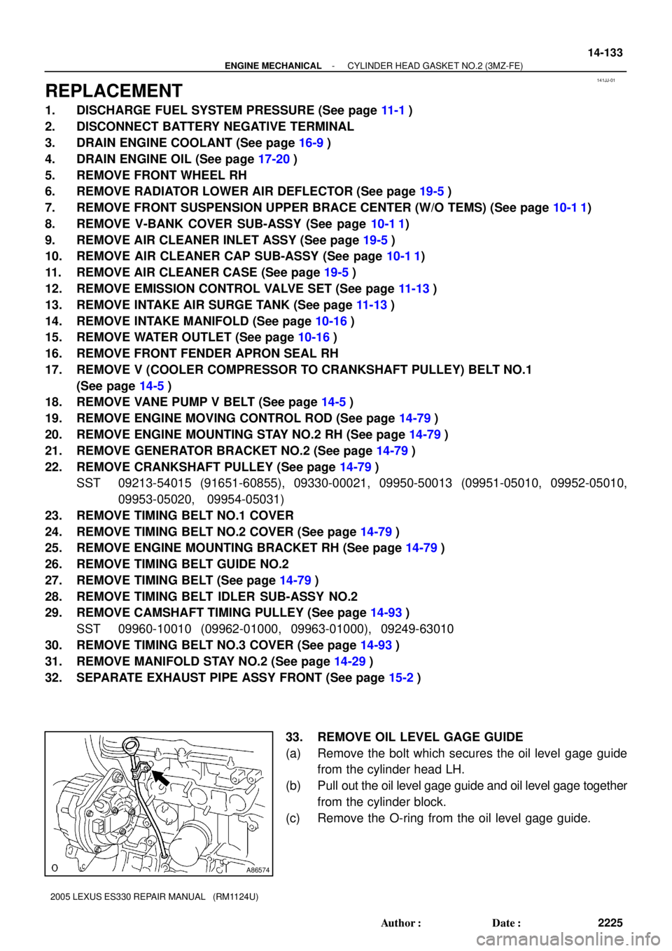
33. REMOVE OIL LEVEL GAGE GUIDE
(a) Remove the bolt which secures the oil level gage guide
from the cylinder head LH.
(b) Pull out the oil level gage guide and oil level gage together
from the cylinder block.
(c) Remove the O-ring from the oil level gage guide.
Page 513 of 969
- ENGINE MECHANICALCYLINDER HEAD GASKET NO.2 (3MZ-FE)
14-137
2229 Author�: Date�:
2005 LEXUS ES330 REPAIR MANUAL (RM1124U)
85. CHECK FOR EXHAUST GAS LEAKS
86. INSPECT IGNITION TIMING (See page 14-1)
SST 09843-18040
87. INSPECT ENGINE IDLE SPEED (See page 14-1)
88. INSPECT COMPRESSION (See page 14-1)
SST 09992-00500
89. INSPECT CO/HC (See page 14-1)
90. SYSTEM INITIALIZATION (See page 19-15)
Page 558 of 969
100IZ-01
A86347DLC3
Hand-held Tester
A86347DLC3
Hand-held Tester
- ENGINE CONTROL SYSTEMSFI SYSTEM (3MZ-FE)
10-1
2006 Author�: Date�:
2005 LEXUS ES330 REPAIR MANUAL (RM1124U)
SFI SYSTEM (3MZ-FE)
ON-VEHICLE INSPECTION
1. INSPECT CAMSHAFT TIMING OIL CONTROL VALVE
ASSY
(a) Check the operation.
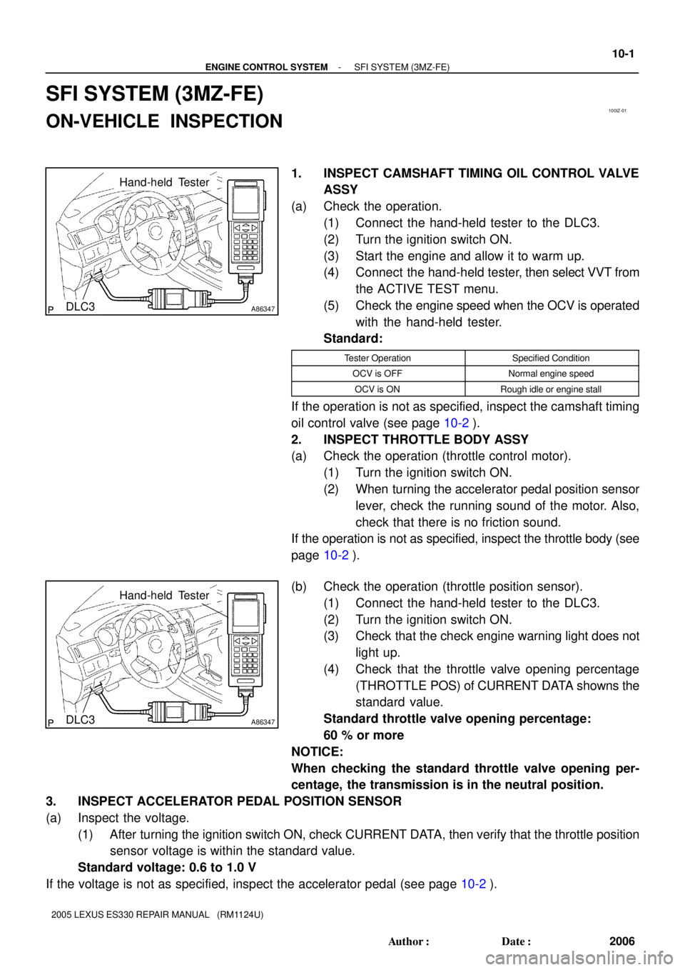
(1) Connect the hand-held tester to the DLC3.
(2) Turn the ignition switch ON.
(3) Start the engine and allow it to warm up.
(4) Connect the hand-held tester, then select VVT from
the ACTIVE TEST menu.
(5) Check the engine speed when the OCV is operated
with the hand-held tester.
Standard:
Tester OperationSpecified Condition
OCV is OFFNormal engine speed
OCV is ONRough idle or engine stall
If the operation is not as specified, inspect the camshaft timing
oil control valve (see page 10-2).
2. INSPECT THROTTLE BODY ASSY
(a) Check the operation (throttle control motor).
(1) Turn the ignition switch ON.
(2) When turning the accelerator pedal position sensor
lever, check the running sound of the motor. Also,
check that there is no friction sound.
If the operation is not as specified, inspect the throttle body (see
page 10-2).
(b) Check the operation (throttle position sensor).
(1) Connect the hand-held tester to the DLC3.
(2) Turn the ignition switch ON.
(3) Check that the check engine warning light does not
light up.
(4) Check that the throttle valve opening percentage
(THROTTLE POS) of CURRENT DATA showns the
standard value.
Standard throttle valve opening percentage:
60 % or more
NOTICE:
When checking the standard throttle valve opening per-
centage, the transmission is in the neutral position.
3. INSPECT ACCELERATOR PEDAL POSITION SENSOR
(a) Inspect the voltage.
(1) After turning the ignition switch ON, check CURRENT DATA, then verify that the throttle position
sensor voltage is within the standard value.
Standard voltage: 0.6 to 1.0 V
If the voltage is not as specified, inspect the accelerator pedal (see page 10-2).
Page 559 of 969

100J0-01
A86282
Ohmmeter
A86283Battery Spool Valve
A84676Battery Voltmeter
Air 10-2
- ENGINE CONTROL SYSTEMSFI SYSTEM (3MZ-FE)
2007 Author�: Date�:
2005 LEXUS ES330 REPAIR MANUAL (RM1124U)
INSPECTION
1. INSPECT CAMSHAFT TIMING OIL CONTROL VALVE
ASSY
(a) Inspect the resistance.
(1) Using an ohmmeter, measure the resistance be-
tween the terminals.
Standard:
Tester ConnectionSpecified Condition
1 (-) - 2 (+)6.9 to 7.9 W at 20�C (68�F)
If the resistance is not as specified, replace the camshaft timing
oil control valve.
(b) Check the operation.
(1) Connect the positive (+) lead from the battery to ter-
minal 2 (+) and negative (-) lead to terminal 1 (-),
then check the movement of the spool valve.
NOTICE:
Confirm that the spool valve moves freely and does not get
stuck in any position.
HINT:
Bad returning of the spool valve resulted from catching foreign
objects causes subtle pressure leak to the advanced direction.
In that case, DTC can be detected.
2. INSPECT MASS AIR FLOW METER
(a) Check the operation.
(1) Apply battery voltage across terminals 1 (+B) and 2
(E2G).
(2) Using voltmeter, connect the positive (+) tester
probe to terminal 3 (VC), and negative (-) tester
probe to terminal 2 (E2G).
(3) Blow air into the mass air flow sensor, then check
that the voltage fluctuates.
If the operation is not as specified, replace the mass air flow
sensor.
Page 560 of 969

A84677
Ohmmeter
-20 0 20406080
(-4) (32) (68)(104)(140)(176)
Temperature �C (�F) 30
0.2 0.515 10 20
Resistance kW
A84678
Ohmmeter
-20 0 20406080
(-4) (32) (68)(104)(140)(176)
Temperature �C (�F) 30
0.2 0.515 10 20
Resistance kW
- ENGINE CONTROL SYSTEMSFI SYSTEM (3MZ-FE)
10-3
2008 Author�: Date�:
2005 LEXUS ES330 REPAIR MANUAL (RM1124U)
(b) Inspect the resistance.
(1) Using an ohmmeter, measure the resistance be-
tween the terminals.
Standard:
Tester ConnectionSpecified Condition
4 (THA) - 5 (E2)13.6 to 18.4 kW at -20�C (-4�F)
4 (THA) - 5 (E2)2.21 to 2.69 kW at 20�C (68�F)
4 (THA) - 5 (E2)0.493 to 0.667 kW at 60�C (140�F)
If the resistance is not as specified, replace the mass air flow
sensor.
3. INSPECT ENGINE COOLANT TEMPERATURE
SENSOR
(a) Inspect the resistance.
(1) Using an ohmmeter, measure the resistance be-
tween the terminals.
Standard:
Tester ConnectionSpecified Condition
1 (E2) - 2 (THW)2.32 to 2.59 kW at 20�C (68�F)
1 (E2) - 2 (THW)0.310 to 0.326 kW at 80�C (176�F)
NOTICE:
When checking the engine coolant temperature sensor in
water, be careful not to allow water to intrude into the termi-
nals. Then dry the engine coolant temperature sensor after
checking.
If the resistance is not as specified, replace the engine coolant
temperature sensor.
Page 561 of 969

A86281
Ohmmeter
A84680
Ohmmeter
A86284
Ohmmeter 10-4
- ENGINE CONTROL SYSTEMSFI SYSTEM (3MZ-FE)
2009 Author�: Date�:
2005 LEXUS ES330 REPAIR MANUAL (RM1124U)
4. INSPECT THROTTLE BODY ASSY
(a) Inspect the resistance.
(1) Using an ohmmeter, measure the resistance be-
tween the terminals.
Standard:
Tester ConnectionSpecified Condition
1 (M-) - 2 (M+)0.3 to 100 W at 20�C (68�F)
3 (E2) - 5 (VC)1.2 to 3.2 kW at 20�C (68�F)
If the resistance is not as specified, replace the throttle body.
5. INSPECT KNOCK SENSOR
(a) Inspect the resistance.
(1) Using an ohmmeter, measure the resistance be-
tween the terminals.
Standard:
Tester ConnectionSpecified Condition
1 (Output)- 2 (Ground)120 to 280 W at 20�C (68�F)
If the resistance is not specified, replace the knock sensor.
6. INSPECT ACCELERATOR PEDAL ASSY (NORMAL
PEDAL)
(a) Inspect the resistance.
(1) Using an ohmmeter, measure the resistance be-
tween the terminals.
Standard:
Tester ConnectionSpecified Condition
2 (VPA2) - 3 (EP1)5.0 kW or less
1 (EP2) - 5 (VPA1)5.0 kW or less
3 (EP1) - 6 (VCP1)2.25 to 4.75 kW
1 (EP2) - 4 (VCP2)2.25 to 4.75 kW
If the resistance is not specified, replace the accelerator pedal.
Page 562 of 969

A86285
Ohmmeter
A84683
OhmmeterBattery
A84683
OhmmeterBattery
- ENGINE CONTROL SYSTEMSFI SYSTEM (3MZ-FE)
10-5
2010 Author�: Date�:
2005 LEXUS ES330 REPAIR MANUAL (RM1124U)
7. INSPECT ACCELERATOR & BRAKE PEDAL ASSY
(POWER PEDAL)
(a) Inspect the resistance.
(1) Using an ohmmeter, measure the resistance be-
tween the terminals.
Standard:
Tester ConnectionSpecified Condition
3 (EP1) - 5 (VPA1)5.0 kW or less
1 (EP2) - 2 (VPA2)5.0 kW or less
3 (EP1) - 6 (VCP1)2.25 to 4.75 kW
1 (EP2) - 4 (VCP2)2.25 to 4.75 kW
If the resistance is not specified, replace the accelerator &
brake pedal.
8. INSPECT MAIN RELAY
(a) Inspect the resistance.
(1) Using an ohmmeter, measure the resistance be-
tween the terminals.
Standard:
Tester ConnectionSpecified Condition
3 - 510 kW or higher
3 - 5Below 1W
(Apply battery voltage to terminals 1 and 2
If the result is not as specified, replace the main relay.
9. INSPECT CIRCUIT OPENING RELAY
(a) Inspect the resistance.
(1) Using an ohmmeter, measure the resistance be-
tween the terminals.
Standard:
Tester ConnectionSpecified Condition
3 - 510 kW or higher
3 - 5Below 1W
(Apply battery voltage to terminals 1 and 2
If the result is not as specified, replace the circuit opening relay.