Page 697 of 969

18-1
2326 Author�: Date�:
2005 LEXUS ES330 REPAIR MANUAL (RM1124U)
IGNITION SYSTEM (3MZ-FE)
ON-VEHICLE INSPECTION
NOTICE:
ºColdº and ºHotº in this se")
1809A-01
- IGNITIONIGNITION SYSTEM (3MZ-FE)
18-1
2326 Author�: Date�:
2005 LEXUS ES330 REPAIR MANUAL (RM1124U)
IGNITION SYSTEM (3MZ-FE)
ON-VEHICLE INSPECTION
NOTICE:
ºColdº and ºHotº in this section mean temperature of the coils themselves. ºColdº is from -10�C
(14�F) to 50�C (122�F) and ºHotº is from 50�C (122�F) to 100�C (212�F).
1. INSPECT IGNITION COIL AND SPARK TEST
(a) Check the DTCs.
NOTICE:
If a DTC is present, perform troubleshooting in accordance with a procedure for that DTC.
(b) Check that a spark occurs.
(1) Remove the 6 ignition coils (see page 18-7).
(2) Using a spark plug wrench 16 mm, remove the 6 spark plugs.
Torque: 25 NVm (250 kgfVcm, 18 ftVlbf)
(3) Install the spark plugs to each ignition coil, then connect the ignition coil connectors.
(4) Disconnect the 6 fuel injector connectors.
(5) Ground the spark plugs.
(6) Check that the spark plug occurs at each spark plug while the engine is being cranked.
NOTICE:
�Be sure to ground the spark plugs when checking.
�Replace the ignition coil if physical impact is felt.
�Do not crank the engine for more than 2 seconds.
If a spark does not occur, perform the following test.
1 SPARK TEST
NG
2 CHECK CONNECTION OF IGNITION COIL CONNECTOR
NG CONNECT SECURELY
OK
3 REPLACE IT WITH NORMAL IGNITION COIL AND PERFORM SPARK TEST AGAIN
OK REPLACE IGNITION COIL ASSY
(See page 18-7)
NG
4 CHECK POWER SUPPLY TO IGNITION COIL
(a) Turn the ignition switch ON.
(b) Check that there is battery voltage at the ignition coil positive (+) terminal.
NG CHECK WIRE HARNESS (BETWEEN IGNITION
(START) SWITCH ASSY AND IGNITION COIL
ASSY)
OK
Page 701 of 969

(b)
A78529
LH Bank:
(a)
(b)
- IGNITIONVVT SENSOR (3MZ-FE)
18-5
2330 Author�: Date�:
2005 LEXUS ES330 REPAIR MANUAL (RM1124U)
VVT SENSOR (3MZ-FE)
REPLACEMENT
1. DISCONNEC")
1809C-01
A79541
RH Bank:
(a)
(b)
A78529
LH Bank:
(a)
(b)
- IGNITIONVVT SENSOR (3MZ-FE)
18-5
2330 Author�: Date�:
2005 LEXUS ES330 REPAIR MANUAL (RM1124U)
VVT SENSOR (3MZ-FE)
REPLACEMENT
1. DISCONNECT ENGINE WIRE NO. 3 (BATTERY NEGATIVE TERMINAL)
2. REMOVE RADIATOR LOWER AIR DEFLECTOR (See page 19-5)
3. REMOVE AIR CLEANER INLET ASSY (See page 19-5)
4. REMOVE AIR CLEANER ASSY (See page 19-5)
5. REMOVE VVT SENSOR
(a) Remove the 2 VVT sensor connectors.
(b) Remove the 2 bolts, then remove the 2 VVT sensors.
HINT:
The VVT sensor is installed with the bolt.
6. INSTALL VVT SENSOR
(a) Apply a light coat of engine oil to the O-ring on each VVT sensor.
(b) Install the 2 VVT sensors with the 2 bolts.
Torque: 8.0 NVm (80 kgfVcm, 71 in.Vlbf)
NOTICE:
Be careful not to twist the O-ring.
(c) Connect the 2 VVT sensor connectors.
7. INSTALL AIR CLEANER ASSY (See page 19-5)
8. INSTALL AIR CLEANER INLET ASSY (See page 19-5)
9. INSTALL RADIATOR LOWER AIR DEFLECTOR
10. CHECK CONNECTION OF VACUUM HOSE (See page 14-29)
11. CONNECT ENGINE WIRE NO. 3 (BATTERY NEGATIVE TERMINAL)
Torque: 5.4 NVm (55 kgfVcm, 48 in.Vlbf)
12. CHECK FOR ENGINE OIL LEAKS
13. SYSTEM INITIALIZATION (See page 19-15)
Page 702 of 969
1809D-01
A86232
A86233
A79763
(a)
(b) 18-6
- IGNITIONCRANKSHAFT POSITION SENSOR (3MZ-FE)
2331 Author�: Date�:
2005 LEXUS ES330 REPAIR MANUAL (RM1124U)
CRANKSHAFT POSITION SENSOR (3MZ-FE)
REPLACEMENT
1. DISCONNECT ENGINE WIRE NO. 3 (BATTERY NEGATIVE TERMINAL)
2. REMOVE ENGINE UNDER COVER NO.1
(a) Remove the 3 clips and 5 screws, then remove the engine
under cover No. 1.
3. REMOVE FRONT FENDER APRON SEAL RH
(a) Remove the clip and 2 bolts, then remove the front fender
apron seal.
4. REMOVE CRANKSHAFT POSITION SENSOR
(a) Remove the crankshaft position sensor connector.
(b) Remove the bolt, then remove the crankshaft position
sensor.
5. INSTALL CRANKSHAFT POSITION SENSOR
Torque: 8.0 NVm (80 kgfVcm, 71 in.Vlbf)
6. INSTALL FRONT FENDER APRON SEAL RH
7. INSTALL ENGINE UNDER COVER NO.1
8. CONNECT ENGINE WIRE NO. 3 (BATTERY NEGATIVE TERMINAL)
Torque: 5.4 NVm (55 kgfVcm, 48 in.Vlbf)
9. SYSTEM INITIALIZATION (See page 19-15)
Page 703 of 969
(b)
(b)
(b)(a)
(a)
RH Bank:
A86235
(a)
(b)(b)
(b)
(a)
(a)LH Bank:
- IGNITIONIGNITION COIL ASSY (3MZ-FE)
18-7
2332 Author�: Date�:
2005 LEXUS ES330 REPAIR MANUAL (RM1124U)
IGNITION")
1809E-02
A86234
(a)(b)
(b)
(b)(a)
(a)
RH Bank:
A86235
(a)
(b)(b)
(b)
(a)
(a)LH Bank:
- IGNITIONIGNITION COIL ASSY (3MZ-FE)
18-7
2332 Author�: Date�:
2005 LEXUS ES330 REPAIR MANUAL (RM1124U)
IGNITION COIL ASSY (3MZ-FE)
REPLACEMENT
1. DISCONNECT ENGINE WIRE NO. 3 (BATTERY NEGATIVE TERMINAL)
2. DRAIN ENGINE COOLANT (RH BANK) (See page 10-1 1)
3. REMOVE FRONT SUSPENSION UPPER BRACE CENTER (W/O TEMS, RH BANK)
(See page 16-9)
4. REMOVE V-BANK COVER SUB-ASSY (See page 16-9)
5. REMOVE AIR CLEANER CAP SUB-ASSY (RH BANK) (See page 16-9)
6. REMOVE EMISSION CONTROL VALVE SET (RH BANK) (See page 11-13)
7. REMOVE INTAKE AIR SURGE TANK (RH BANK) (See page 11-13)
8. REMOVE IGNITION COIL ASSY
(a) Disconnect the 6 connectors.
(b) Remove the 6 bolts, then remove the 6 ignition coils.
HINT:
The ignition coil is installed with the bolt.
9. INSTALL IGNITION COIL ASSY
Torque: 8.0 NVm (80 kgfVcm, 71 in.Vlbf)
10. INSTALL INTAKE AIR SURGE TANK (RH BANK) (See page 11-13)
11. INSTALL EMISSION CONTROL VALVE SET (RH BANK) (See page 11-13)
12. INSTALL AIR CLEANER CAP SUB-ASSY (RH BANK) (See page 16-9)
13. CHECK CONNECTION OF VACUUM HOSE (RH BANK) (See page 14-29)
14. CONNECT ENGINE WIRE NO. 3 (BATTERY NEGATIVE TERMINAL)
Torque: 5.4 NVm (55 kgfVcm, 48 in.Vlbf)
15. ADD ENGINE COOLANT (RH BANK) (See page 10-1 1)
16. CHECK FOR ENGINE COOLANT LEAKS (RH BANK) (See page 16-1)
17. INSTALL V-BANK COVER SUB-ASSY (See page 16-9)
18. INSTALL FRONT SUSPENSION UPPER BRACE CENTER (W/O TEMS, RH BANK)
(See page 16-9)
19. SYSTEM INITIALIZATION (See page 19-15)
Page 706 of 969
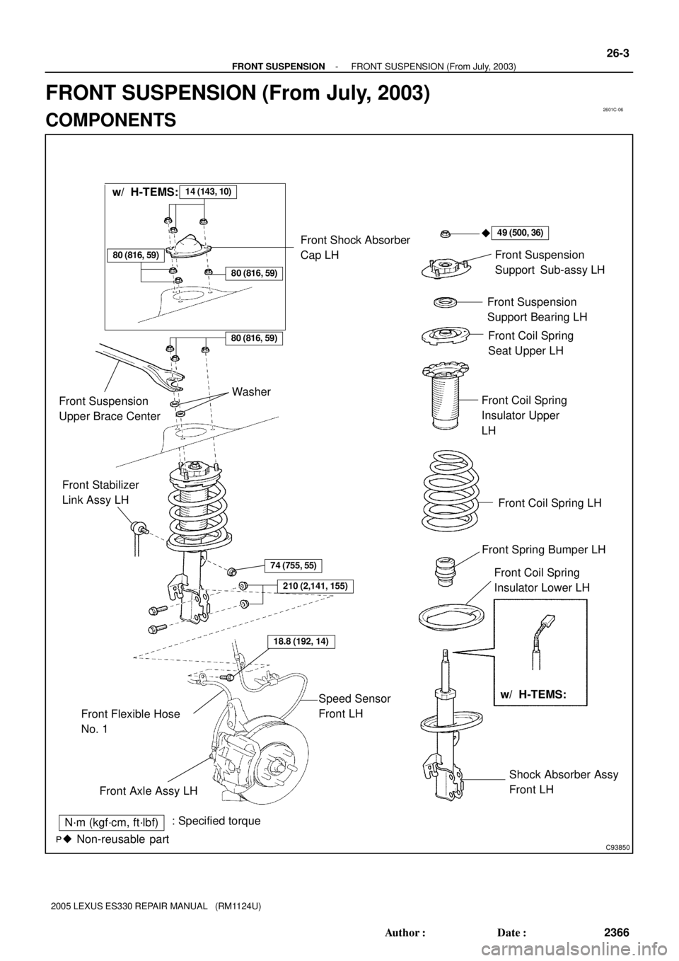
2601C-06
C93850
N´m (kgf´cm, ft´lbf): Specified torque
� Non-reusable part�
Front Suspension
Support Sub-assy LH
Front Suspension
Support Bearing LH
Front Coil Spring
Seat Upper LH
Front Coil Spring
Insulator Upper
LH
Front Coil Spring LH
Front Spring Bumper LH
Front Coil Spring
Insulator Lower LH
Shock Absorber Assy
Front LH Front Stabilizer
Link Assy LH
Front Flexible Hose
No. 1
74 (755, 55)
Speed Sensor
Front LH
Front Axle Assy LH
49 (500, 36)
18.8 (192, 14)
14 (143, 10)
80 (816, 59)
w/ H-TEMS: w/ H-TEMS:
Front Shock Absorber
Cap LH
80 (816, 59)
80 (816, 59)
Front Suspension
Upper Brace CenterWasher
210 (2,141, 155)
- FRONT SUSPENSIONFRONT SUSPENSION (From July, 2003)
26-3
2366 Author�: Date�:
2005 LEXUS ES330 REPAIR MANUAL (RM1124U)
FRONT SUSPENSION (From July, 2003)
COMPONENTS
Page 707 of 969
C93097
74 (755, 55)
Front Stabilizer
Link Assy RH
Stabilizer Bar FrontFront Stabilizer Bracket No. 1 RH
Front Stabilizer Bar Bush No. 1
Front Stabilizer Bracket No. 1 LH
Front Stabilizer Link Assy LH
Rack & Pinion Power
Steering Gear Assy
Speed Sensor
Front LH
Front Frame Assy
Front Lower Arm
Bush Stopper
Lower Ball Joint
Assy Front LH
Front Suspension
Arm Sub-assy
Lower No. 1 LHFront Brake
Caliper Assy
Front Axle Assy LH �Cotter Pin
19 (194, 14)
�Cotter Pin
N´m (kgf´cm, ft´lbf): Specified torque
� Non-reusable part
Front Disc
74 (755, 55)
74 (755, 55)
206 (2,101, 152)
294 (2,998, 217)
49 (500, 36)
87 (887, 64)
123 (1,254 91)
200 (2,039, 148)
200 (2,039, 148)
75 (765, 55)
70 (714, 52)
70 (714, 52)
8.0 (82, 71 in.Vlbf)
106.9 (1,090, 79)
106.9 (1,090, 79)
19 (194, 14)
�
210 (2,141, 155)
95 (969, 70)
Transverse Engine
Engine Mounting
Insulator
26-4
- FRONT SUSPENSIONFRONT SUSPENSION (From July, 2003)
2367 Author�: Date�:
2005 LEXUS ES330 REPAIR MANUAL (RM1124U)
Page 708 of 969

26-5
2368 Author�: Date�:
2005 LEXUS ES330 REPAIR MANUAL (RM1124U)
FRO")
2605T-05
C91608
B Front:A
C91609
C Rear:
D
SA3213
A
DB
Front
C
F40165
- FRONT SUSPENSIONFRONT WHEEL ALIGNMENT (From July, 2003)
26-5
2368 Author�: Date�:
2005 LEXUS ES330 REPAIR MANUAL (RM1124U)
FRONT WHEEL ALIGNMENT (From July, 2003)
ADJUSTMENT
1. INSPECT TIRE (See page 26-5)
2. MEASURE VEHICLE HEIGHT
Vehicle height:
FrontA - B: 120 mm (4.72 in.)
RearD - C: 52 mm (2.05 in.)
Measuring points:
A: Ground clearance of front wheel center
B: Ground clearance of lower suspension arm No. 2 set bolt
center
C: Ground clearance of strut rod set bolt center
D: Ground clearance of rear wheel center
NOTICE:
Before inspecting the wheel alignment, adjust the vehicle
height to the specified value.
HINT:
Bounce the vehicle at the corners up and down to stabilize the
suspension and inspect the vehicle height.
3. INSPECT TOE-IN
Toe-in:
Toe-in
(total)A + B: 0° ± 12' (0° ± 0.2°)
C - D: 0 ± 2 mm (0 ± 0.08 in.)
If the toe-in is not within the specified value, adjust it at the rack
ends.
4. ADJUST TOE-IN
(a) Remove the rack boot set clips.
(b) Loosen the tie rod end lock nuts.
(c) Turn the right and left rack ends by an equal amount to
adjust the toe-in.
HINT:
Try to adjust the toe-in to the center of the specified value.
(d) Make sure that the lengths of the right and left rack ends
are the same.
(e) Torque the tie rod end lock nuts.
Torque: 74 N´m (755 kgf´cm, 55 ft´lbf)
(f) Place the boots on the seats and install the clips.
HINT:
Make sure that the boots are not twisted.
(g) Perform VSC system calibration. (See page 05-471)
Page 710 of 969

C93869
1
2
Bolt
Adjusting
ValueSet BoltAdjusting Bolt90105-17008 90105-17009 90105-17010 90105-17011
121212121 Dot
2 Dots3 Dots
15'
30'
45'
1�00'
1�15'
1�30'
- FRONT SUSPENSIONFRONT WHEEL ALIGNMENT (From July, 2003)
26-7
2370 Author�: Date�:
2005 LEXUS ES330 REPAIR MANUAL (RM1124U)
(e) Adjust the camber by pushing or pulling the lower side of
the shock absorber in the direction in which the camber
adjustment is required.
(f) Tighten the nuts.
Torque: 210 NVm (2,141 kgfVcm, 155 ftVlbf)
NOTICE:
When installing the nuts, keep the bolts from rotating and
then torque the nut.
(g) Install the front wheel.
Torque: 103 N´m (1,050 kgf´cm, 76 ft´lbf)
(h) Check the camber.
HINT:
�Try to adjust the camber to the center of the specified val-
ue.
�Adjusting value for the set bolts is 6' to 30' (0.1° to 0.5°).
If the camber is not within the specified valve, estimate how
much additional camber adjustment will be required, and select
the camber adjusting bolt.
NOTICE:
Tighten the adjusting bolt with a new nut.
(i) Do the steps mentioned above again. At step (b), replace
1 or 2 selected bolts.
HINT:
When replacing the 2 bolts, replace 1 bolt for each time.


Front Stabilizer
Link Assy RH
Stabilizer Bar FrontFront Stabilizer Bracket No. 1 RH
Front Stabilizer Bar Bush No. 1
Front Stabilizer Bracket No. 1 LH
Front Stabilizer Link Assy LH")