Page 714 of 969

(g) Install a new f")
F40162
F40169
OutsideOutside
F40140
C93871
C93102
SST
- FRONT SUSPENSIONFRONT SHOCK ABSORBER WITH COIL SPRING
26-1 1
2374 Author�: Date�:
2005 LEXUS ES330 REPAIR MANUAL (RM1124U)
(g) Install a new front suspension support bearing LH.
(h) Install the front suspension support sub-assy LH with the
mark facing to the outside of the vehicle.
(i) Temporarily tighten the new lock nut.
9. INSTALL FRONT SHOCK ABSORBER WITH COIL
SPRING
(a) Install the front shock absorber with coil spring as shown
in the illustration.
(b) Install the 3 nuts to the upper side of front shock absorber
with coil spring.
Torque: 80 NVm (816 kgfVcm, 59 ftVlbf)
NOTICE:
Be careful not to drop the 2 washers in the case that there
is front suspension upper brace center.
(c) Install the 2 bolts and 2 nuts to the lower side of front
shock absorber with coil spring.
Torque: 210 NVm (2,141 kgfVcm, 155 ftVlbf)
NOTICE:
When installing bolt, stop the bolt from rotating and torque
the nut.
(d) w/ H-TEMS:
Using SST, fully tighten the lock nut.
SST 09817-33190
Torque: 49 NVm (500 kgfVcm, 36 ftVlbf)
(e) w/o H-TEMS:
Fully tighten the lock nut.
Torque: 49 NVm (500 kgfVcm, 36 ftVlbf)
Page 715 of 969
C65925
C91030
F40136
26-12
- FRONT SUSPENSIONFRONT SHOCK ABSORBER WITH COIL SPRING
2375 Author�: Date�:
2005 LEXUS ES330 REPAIR MANUAL (RM1124U)
(f) Install the front flexible hose No. 1 and speed sensor front
LH with the bolt.
Torque: 18.8 NVm (192 kgfVcm, 14 ftVlbf)
10. INSTALL FRONT SHOCK ABSORBER CAP LH
(H-TEMS SUSPENSION)
(a) Install the front shock absorber cap LH with the 3 nuts.
Torque: 14 NVm (143 kgfVcm, 10 ftVlbf)
(b) Disconnect the connector, install the harness clamp.
11. INSTALL FRONT STABILIZER LINK ASSY LH
(a) Install the front stabilizer link assy LH with the nut.
Torque: 74 NVm (755 kgfVcm, 55 ftVlbf)
HINT:
If the ball joint turns together with the nut, use a hexagon (6 mm)
wrench to hold the stud.
12. INSTALL FRONT WHEEL
Torque: 103 NVm (1,050 kgfVcm, 76 ftVlbf)
13. INSPECT AND ADJUST FRONT WHEEL ALIGNMENT (See page 26-5)
Page 718 of 969
C91606
F02227
C83387
- FRONT SUSPENSIONFRONT SUSPENSION ARM SUB-ASSY LOWER NO.1
LH (From July, 2003)26-15
2378 Author�: Date�:
2005 LEXUS ES330 REPAIR MANUAL (RM1124U)
4. INSTALL FRONT SUSPENSION ARM SUB- ASSY
LOWER NO.1 LH
(a) Install the front lower arm bush stopper to the front sus-
pension arm sub-assy lower No. 1 LH.
(b) Install the front suspension arm sub-assy lower No. 1 LH
with the 2 bolts to the front side.
Torque: 200 NVm (2,039 kgfVcm, 148 ftVlbf)
(c) Install the front suspension arm sub-assy lower No. 1 LH
with the bolt and nut to the rear side.
Torque: 206 NVm (2,101 kgfVcm, 152 ftVlbf)
5. INSTALL TRANSVERSE ENGINE ENGINE MOUNTING
INSULATOR
(a) Install the transverse engine engine mounting insulator
with the 3 nuts.
Torque: 87 NVm (887 kgfVcm, 64 ftVlbf)
6. INSTALL ENGINE ASSEMBLY WITH TRANSAXLE (See page 14-29)
Page 719 of 969

LOWER BALL JOINT ASSY FRONT LH
REPLACEMENT
HINT:
CONPONENTS: See")
2601I-09
ZX1712
26-16
- FRONT SUSPENSIONLOWER BALL JOINT ASSY FRONT LH
2379 Author�: Date�:
2005 LEXUS ES330 REPAIR MANUAL (RM1124U)
LOWER BALL JOINT ASSY FRONT LH
REPLACEMENT
HINT:
CONPONENTS: See page 26-3.
1. REMOVE FRONT WHEEL
2. REMOVE FRONT AXLE HUB LH NUT (See page 30-8)
SST 09930-00010
3. DISCONNECT SPEED SENSOR FRONT LH (See page 30-8)
4. DISCONNECT FRONT DISC BRAKE CALIPER ASSY LH (See page 30-19)
5. REMOVE FRONT DISC
6. DISCONNECT TIE ROD ASSY LH (See page 30-8)
SST 09628-6201 1
7. DISCONNECT FRONT SUSPENSION ARM SUB-ASSY LOWER NO.1 LH (See page 30-8)
8. REMOVE FRONT AXLE ASSY LH (See page 30-19)
9. REMOVE LOWER BALL JOINT ASSY FRONT LH (See page 30-19)
SST 09628-6201 1
10. INSPECT LOWER BALL JOINT ASSY FRONT LH
(a) As shown in the illustration, flip the ball joint stud back and
forth 5 times, before installing the nut.
(b) Using a torque wrench, turn the nut continuously at a rate
of 3 - 5 seconds per 1 turn and take the torque reading
on the 5th turn.
Turning torque:
0.98 - 3.43 N´m (10 - 35 kgf´cm, 8.7 - 30 in.´lbf)
11. INSTALL LOWER BALL JOINT ASSY FRONT LH (See page 30-19)
12. INSTALL FRONT AXLE ASSY LH (See page 30-19)
13. INSTALL FRONT SUSPENSION ARM SUB-ASSY LOWER NO.1 LH (See page 30-8)
14. INSTALL TIE ROD ASSY LH (See page 30-8)
15. INSTALL FRONT DISC
16. INSTALL FRONT DISC BRAKE CALIPER ASSY LH (See page 30-19)
17. INSTALL SPEED SENSOR FRONT LH (See page 30-8)
18. INSTALL FRONT AXLE HUB LH NUT (See page 30-8)
19. INSTALL FRONT WHEEL
Torque: 103 NVm (1,050 kgfVcm, 76 ftVlbf)
20. INSPECT AND ADJUST FRONT WHEEL ALIGNMENT (See page 26-5)
21. CHECK ABS SPEED SENSOR SIGNAL
w/ VSC (See page 05-471)
w/o VSC (See page 05-420)
Page 721 of 969

12. REMOVE STABILIZER BAR FRONT
13. REMOVE")
C66721
C81547F40197
Inner side
Rear
side
C91607
26-18
- FRONT SUSPENSIONSTABILIZER BAR FRONT
2381 Author�: Date�:
2005 LEXUS ES330 REPAIR MANUAL (RM1124U)
12. REMOVE STABILIZER BAR FRONT
13. REMOVE FRONT STABILIZER BAR BUSH NO.1
14. INSPECT FRONT STABILIZER LINK ASSY LH
(a) As shown in the illustration, flip the ball joint stud back and
forth 5 times, before installing the nut.
(b) Using a torque wrench, turn the nut continuously at a rate
of 2 - 4 seconds per 1 turn and take the torque reading
on the 5th turn.
Turning torque:
0.05 - 1.96 N´m (0.5 - 20 kgf´cm, 0.4 - 17.4 in.´lbf)
15. INSTALL FRONT STABILIZER BAR BUSH NO.1
HINT:
Install the bushing to the inner side of the bushing stopper on
the stabilizer bar.
16. INSTALL STABILIZER BAR FRONT
17. INSTALL RACK & PINION POWER STEERING GEAR ASSY (See page 51-21)
18. INSTALL STEERING INTERMEDIATE SHAFT SUB-ASSY (See page 51-21)
19. INSTALL PRESSURE FEED TUBE ASSY (See page 51-21)
SST 09023-00101
20. INSTALL STEERING GEAR OUTLET RETURN TUBE (See page 51-21)
SST 09023-00101
21. INSTALL TIE ROD ASSY LH (See page 30-8)
22. INSTALL TIE ROD ASSY RH
HINT:
Install the RH side by the same procedures with the LH side.
23. INSTALL FRONT STABILIZER BRACKET NO.1 LH
(a) Install the 2 front stabilizer brackets No. 1 LH with the 2
bolts.
Torque: 19 NVm (194 kgfVcm, 14 ftVlbf)
Page 722 of 969
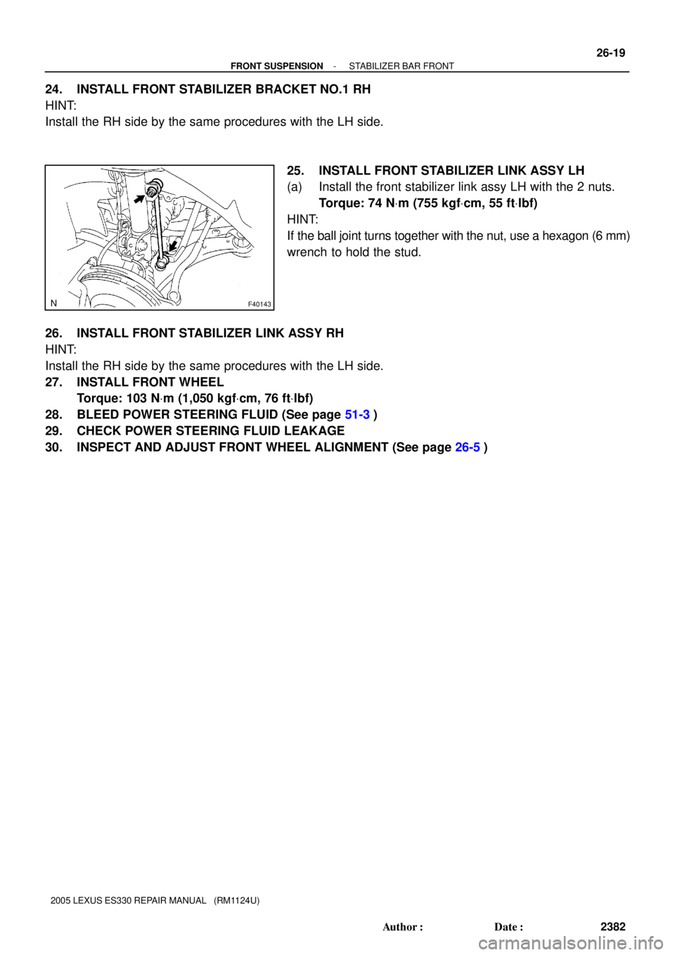
F40143
- FRONT SUSPENSIONSTABILIZER BAR FRONT
26-19
2382 Author�: Date�:
2005 LEXUS ES330 REPAIR MANUAL (RM1124U)
24. INSTALL FRONT STABILIZER BRACKET NO.1 RH
HINT:
Install the RH side by the same procedures with the LH side.
25. INSTALL FRONT STABILIZER LINK ASSY LH
(a) Install the front stabilizer link assy LH with the 2 nuts.
Torque: 74 NVm (755 kgfVcm, 55 ftVlbf)
HINT:
If the ball joint turns together with the nut, use a hexagon (6 mm)
wrench to hold the stud.
26. INSTALL FRONT STABILIZER LINK ASSY RH
HINT:
Install the RH side by the same procedures with the LH side.
27. INSTALL FRONT WHEEL
Torque: 103 NVm (1,050 kgfVcm, 76 ftVlbf)
28. BLEED POWER STEERING FLUID (See page 51-3)
29. CHECK POWER STEERING FLUID LEAKAGE
30. INSPECT AND ADJUST FRONT WHEEL ALIGNMENT (See page 26-5)
Page 728 of 969
F41590
51-6
- POWER STEERINGPOWER STEERING SYSTEM
2581 Author�: Date�:
(j) Disconnect the SST.
SST 09640- 10010 (09641- 01010, 09641- 01020,
09641-01030)
(k) Connect the pressure feed tube assy to the rack & pinion
power steering gear assy (See page 51-21).
(l) Bleed the power steering system.
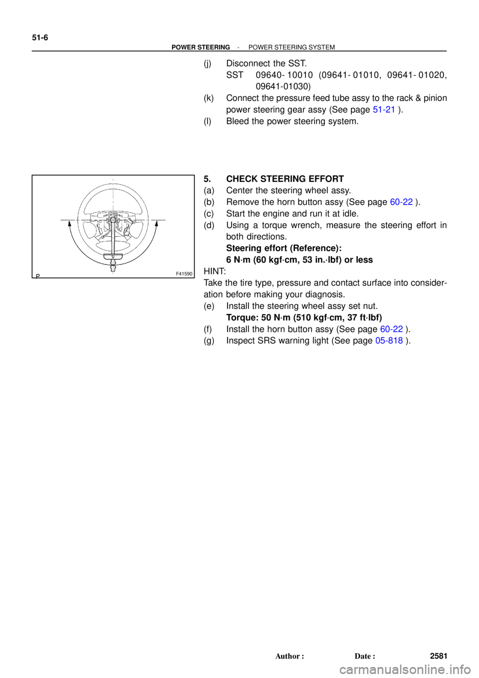
5. CHECK STEERING EFFORT
(a) Center the steering wheel assy.
(b) Remove the horn button assy (See page 60-22).
(c) Start the engine and run it at idle.
(d) Using a torque wrench, measure the steering effort in
both directions.
Steering effort (Reference):
6 N´m (60 kgf´cm, 53 in.´lbf) or less
HINT:
Take the tire type, pressure and contact surface into consider-
ation before making your diagnosis.
(e) Install the steering wheel assy set nut.
Torque: 50 N´m (510 kgf´cm, 37 ft´lbf)
(f) Install the horn button assy (See page 60-22).
(g) Inspect SRS warning light (See page 05-818).
Page 729 of 969
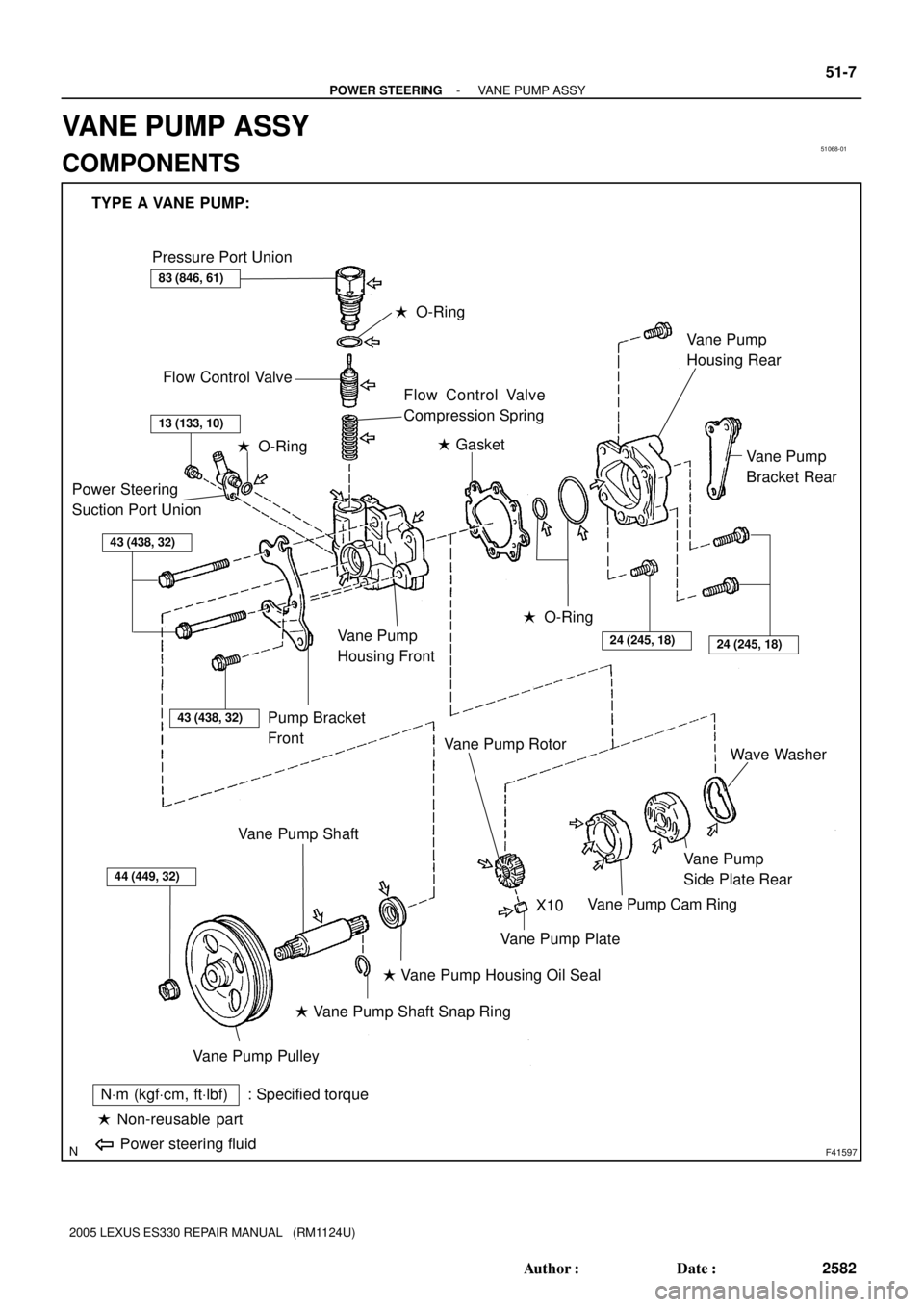
51068-01
F41597
TYPE A VANE PUMP:
Pressure Port Union
Flow Control Valve
� O-Ring
Flow Control Valve
Compression Spring
Power Steering
Suction Port Union
43 (438, 32)
Pump Bracket
Front
Vane Pump
Housing Front
� O-Ring� Gasket
� O-Ring
24 (245, 18)24 (245, 18)
Vane Pump
Bracket Rear Vane Pump
Housing Rear
44 (449, 32)
Vane Pump Pulley
Vane Pump Shaft
� Vane Pump Shaft Snap Ring
� Vane Pump Housing Oil Seal
Vane Pump Plate
Vane Pump Rotor
Vane Pump Cam Ring
Vane Pump
Side Plate RearWave Washer
� Non-reusable part
NVm (kgfVcm, ftVlbf) : Specified torque
Power steering fluid
X10
83 (846, 61)
13 (133, 10)
43 (438, 32)
- POWER STEERINGVANE PUMP ASSY
51-7
2582 Author�: Date�:
2005 LEXUS ES330 REPAIR MANUAL (RM1124U)
VANE PUMP ASSY
COMPONENTS