Page 633 of 969

120BV-02
A91017
Nylon Tube Fuel Tube Joint
O-ring
Tube Joint Clip Fuel Suction Plate
A79488
Tube Joint Clip
A79489
A79491
Cover
Tube Joint Clip
12-20
- EMISSION CONTROLVAPOR PRESSURE SENSOR ASSY (3MZ-FE)
2081 Author�: Date�:
2005 LEXUS ES330 REPAIR MANUAL (RM1124U)
VAPOR PRESSURE SENSOR ASSY (3MZ-FE)
REPLACEMENT
1. DISCHARGE FUEL SYSTEM PRESSURE (See page 11-1)
2. DISCONNECT ENGINE WIRE NO. 3 (BATTERY NEGATIVE TERMINAL)
3. REMOVE REAR SEAT CUSHION ASSY (See page 72-39)
4. REMOVE REAR FLOOR SERVICE HOLE COVER (See page 11-20)
5. DISCONNECT FUEL PUMP TUBE SUB-ASSY
(a) Remove the tube joint clip, then pull out the fuel pump
tube.
NOTICE:
�Check around the quick connector for dirt or mud be-
fore this operation. Remove the dirt if necessary.
�Be careful of mud because the quick connector has
an O-ring which seals the pipe and quick connector
that can be contaminated.
�Do not use any tools in this operation.
�Do not bend or twist the nylon tube. Protect the quick
connector by covering it with a vinyl or plastic bag.
�When the pipe and quick connector are stuck, push
and pull the quick connector to release. Pull the quick
connector carefully.
6. REMOVE FUEL TANK VENT TUBE SET PLATE
(a) Remove the 8 bolts, then remove the fuel tank vent tube
set plate.
7. REMOVE VAPOR PRESSURE SENSOR ASSY
(a) Remove the cover.
(b) Remove the tube joint clip, then pull out the vapor pres-
sure sensor.
Page 634 of 969

12-21
2082 Author�: Date�:
2005 LEXUS ES330 REPAIR MANUAL (RM1124U)
8. INST")
A86272
Cover
Tube Joint Clip
A79489Mark
A81595
Tube Joint ClipCollar
- EMISSION CONTROLVAPOR PRESSURE SENSOR ASSY (3MZ-FE)
12-21
2082 Author�: Date�:
2005 LEXUS ES330 REPAIR MANUAL (RM1124U)
8. INSTALL VAPOR PRESSURE SENSOR ASSY
(a) Install the vapor pressure sensor with the tube joint clip.
NOTICE:
�Check the connected part for scratch or foreign ob-
jects.
�Check that the vapor pressure sensor is inserted se-
curely.
�Check that the tube joint clip is on the collar of the va-
por pressure sensor.
�After installing the tube joint clip, check that the vapor
pressure sensor has not been pulled off.
(b) Install the cover.
9. INSTALL FUEL TANK VENT TUBE SET PLATE
(a) Align the mark of the fuel tank vent tube set plate with the
fuel suction tube w/ pump & gauge.
(b) Install the fuel tank vent tube set plate with the 8 bolts.
Torque: 5.9 NVm (60 kgfVcm, 52 in.Vlbf)
10. CONNECT FUEL PUMP TUBE SUB-ASSY
(a) Install the fuel pump tube with the tube joint clip.
NOTICE:
�Check the connected part for scratch or foreign ob-
jects.
�Check that the fuel tube joint is inserted securely.
�Check that the tube joint clip is on the collar of the fuel
tube joint.
�After installing the tube joint clip, check that the fuel
tube joint has not been pulled off.
11. CONNECT ENGINE WIRE NO. 3 (BATTERY NEGATIVE TERMINAL)
Torque: 5.4 NVm (55 kgfVcm, 48 in.Vlbf)
12. CHECK FOR FUEL LEAKS (See page 11-5)
13. INSTALL REAR FLOOR SERVICE HOLE COVER (See page 11-20)
14. INSTALL REAR SEAT CUSHION ASSY
15. SYSTEM INITIALIZATION (See page 19-15)
Page 645 of 969
150B7-01
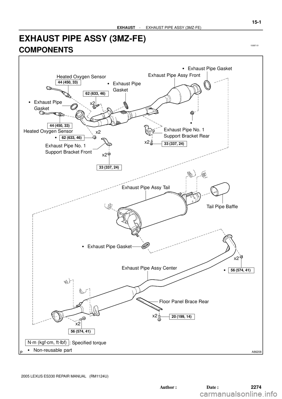
A86208
N´m (kgf´cm, ft´lbf)
: Specified torque
� Non-reusable part � Exhaust Pipe
Gasket
44 (450, 33)
Heated Oxygen Sensor
44 (450, 33)
Heated Oxygen Sensor
�
�
62 (633, 46)
Exhaust Pipe No. 1
Support Bracket Front
33 (337, 24)
Exhaust Pipe No. 1
Support Bracket Rear
33 (337, 24)
x2
x2
x2
Exhaust Pipe Assy Tail
Tail Pipe Baffle
Exhaust Pipe Assy Center
x2
x2
x2
20 (199, 14)
x2
56 (574, 41)
Floor Panel Brace Rear
� Exhaust Pipe Gasket� Exhaust Pipe Gasket
� Exhaust Pipe
Gasket
Exhaust Pipe Assy Front
�56 (574, 41)
62 (633, 46)
- EXHAUSTEXHAUST PIPE ASSY (3MZ-FE)
15-1
2274 Author�: Date�:
2005 LEXUS ES330 REPAIR MANUAL (RM1124U)
EXHAUST PIPE ASSY (3MZ-FE)
COMPONENTS
Page 646 of 969
150B8-01
A86209
A86210
(a)
(b)
(a)
(b)
(b)
A86211
Plastic-faced Hammer
15-2
- EXHAUSTEXHAUST PIPE ASSY (3MZ-FE)
2275 Author�: Date�:
2005 LEXUS ES330 REPAIR MANUAL (RM1124U)
Removal & Installation and Disassembly & Reassembly
1. DISCONNECT ENGINE WIRE NO. 3 (BATTERY NEGATIVE TERMINAL)
2. REMOVE HEATED OXYGEN SENSOR (See page 12-24)
SST 09224-00010
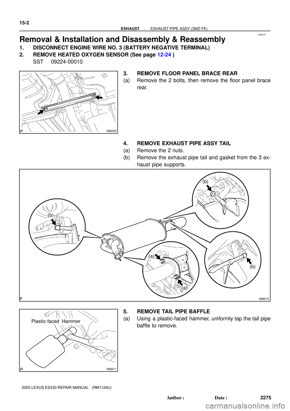
3. REMOVE FLOOR PANEL BRACE REAR
(a) Remove the 2 bolts, then remove the floor panel brace
rear.
4. REMOVE EXHAUST PIPE ASSY TAIL
(a) Remove the 2 nuts.
(b) Remove the exhaust pipe tail and gasket from the 3 ex-
haust pipe supports.
5. REMOVE TAIL PIPE BAFFLE
(a) Using a plastic-faced hammer, uniformly tap the tail pipe
baffle to remove.
Page 649 of 969
A86216
Keyway
KeyPlastic-faced
Hammer
- EXHAUSTEXHAUST PIPE ASSY (3MZ-FE)
15-5
2278 Author�: Date�:
2005 LEXUS ES330 REPAIR MANUAL (RM1124U)
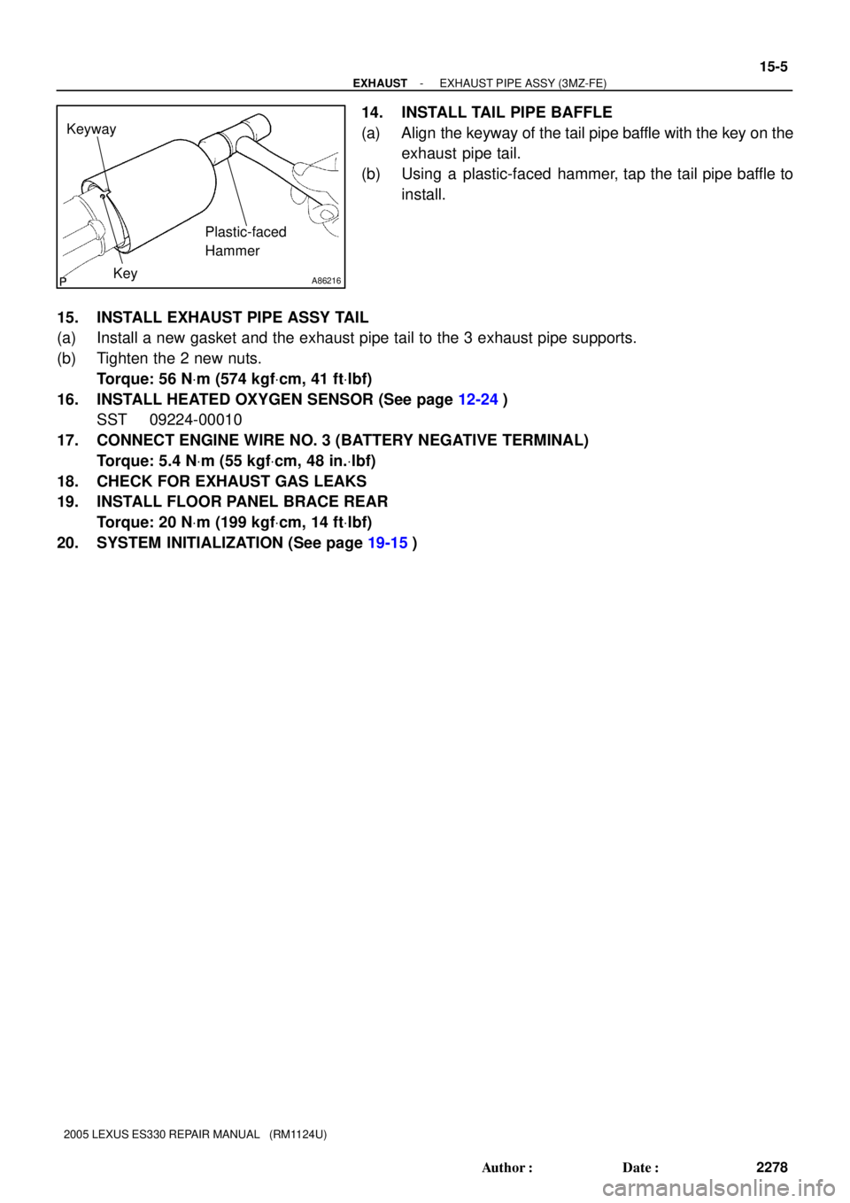
14. INSTALL TAIL PIPE BAFFLE
(a) Align the keyway of the tail pipe baffle with the key on the
exhaust pipe tail.
(b) Using a plastic-faced hammer, tap the tail pipe baffle to
install.
15. INSTALL EXHAUST PIPE ASSY TAIL
(a) Install a new gasket and the exhaust pipe tail to the 3 exhaust pipe supports.
(b) Tighten the 2 new nuts.
Torque: 56 NVm (574 kgfVcm, 41 ftVlbf)
16. INSTALL HEATED OXYGEN SENSOR (See page 12-24)
SST 09224-00010
17. CONNECT ENGINE WIRE NO. 3 (BATTERY NEGATIVE TERMINAL)
Torque: 5.4 NVm (55 kgfVcm, 48 in.Vlbf)
18. CHECK FOR EXHAUST GAS LEAKS
19. INSTALL FLOOR PANEL BRACE REAR
Torque: 20 NVm (199 kgfVcm, 14 ftVlbf)
20. SYSTEM INITIALIZATION (See page 19-15)
Page 818 of 969
 Disconnect the 3 connectors.
(b) Disconnect the airbag connector.
(c) Rem")
C90687
C90688Matchmarks
- STEERING COLUMNSTEERING COLUMN ASSY
50-9
2570 Author�: Date�:
15. REMOVE TURN SIGNAL SWITCH ASSY
(a) Disconnect the 3 connectors.
(b) Disconnect the airbag connector.
(c) Remove the 3 screws and turn signal switch assy.
16. REMOVE INSTRUMENT PANEL FINISH PLATE(See page 71-1 1)
17. DISCONNECT FLOOR SHIFT PARKING LOCK CABLE
ASSY
(a) Place the ignition switch lock cylinder assy at the key ACC
position.
(b) Remove the cable cap claw from the key interlock and pull
out the floor shift parking lock cable assy.
18. DISCONNECT STEERING SLIDING YOKE SUB-ASSY
(a) Place the matchmarks on the steering sliding yoke sub-
assy and intermediate shaft sub-assy.
(b) Remove the bolt and disconnect the steering sliding yoke
sub-assy .
19. REMOVE STEERING COLUMN HOLE COVER SUB-ASSY NO.2
(a) Remove the hose clamp.
(b) Remove the steering column hole cover sub-assy No.2.
20. REMOVE STEERING COLUMN ASSY
(a) Disconnect the connectors and wire harness clamps.
(b) Disconnect the driver side junction block.
Page 822 of 969
 Install the steering column assy with the 2 nuts and bolt.
Torque: 21 NVm")
C90690
C90688
Matchmarks
- STEERING COLUMNSTEERING COLUMN ASSY
50-13
2574 Author�: Date�:
37. INSTALL STEERING COLUMN ASSY
(a) Install the steering column assy with the 2 nuts and bolt.
Torque: 21 NVm (214 kgfVcm, 15 ftVlbf)
(b) Connect the driver side junction block.
(c) Connect the connectors and wire harness clamps.
38. CONNECT STEERING SLIDING YOKE SUB-ASSY
(a) Align the matchmarks on the steering sliding yoke sub-
assy and steering intermediate shaft sub-assy.
(b) Connect the steering sliding yoke sub-assy with the bolt.
Torque: 35 NVm (360 kgfVcm, 26 ftVlbf)
39. CONNECT FLOOR SHIFT PARKING LOCK CABLE ASSY
(a) Place the ignition switch lock cylinder assy at the key ACC position.
(b) Install the floor shift parking lock cable assy.
40. INSPECT CHECK KEY INTERLOCK OPERATION(See page 40-31)
41. INSTALL INSTRUMENT PANEL FINISH PLATE(See page 71-1 1)
42. INSTALL TURN SIGNAL SWITCH ASSY
(a) Install the turn signal switch assy with the 3 screws.
(b) Connect the airbag connector.
(c) Connect the 3 connectors.
43. INSPECT SPIRAL CABLE SUB-ASSY(See page 60-31)
44. INSTALL STEERING COLUMN COVER
(a) Install the steering column cover with the 3 screws.
45. INSTALL STEERING COLUMN COVER LWR NO.2
46. INSTALL HEATER TO FOOT DUCT NO.3(See page 71-1 1)
47. INSTALL INSTRUMENT PANEL INSERT SUB-ASSY LOWER LH
48. INSTALL INSTRUMENT PANEL SUB-ASSY UPPER
49. INSTALL FRONT DOOR SCUFF PLATE LH
50. PLACE FRONT WHEELS FACING STRAIGHT AHEAD
Page 849 of 969
REAR BUCKLE EASE OF USE IMPROVEMENT ± BO011-05 Revised November 9, 2005
Page 3 of 9
9. Remove the rear seat shoulder belt cover.
Using a screwdriver, disengage the 12 claws and remove the 3 rear seat shoulder
belt covers.
HINT:
Tape the screwdriver tip before use.
: Claw
10. Remove the package tray trim panel assembly.
A. Remove the 2 bolts and release the floor anchors of the seat belts.
Repair
Procedure
(Continued)