Page 603 of 969
11-23
2051 Author�: Date�:
2005 LEXUS ES330 REPAIR MANUAL (RM1124U)
15. INSTALL FUEL")
A65038
New O-ring
A65040
O-ring
A86272
Cover
Tube Joint Clip
- FUELFUEL SUCTION W/ PUMP & GAUGE TUBE
ASSY (3MZ-FE)11-23
2051 Author�: Date�:
2005 LEXUS ES330 REPAIR MANUAL (RM1124U)
15. INSTALL FUEL PRESSURE REGULATOR ASSY
(a) Apply a light coat of spindle oil or gasoline to a new O-
ring, then install it to the fuel pressure regulator.
(b) Push in the fuel pressure regulator to the fuel tank fuel fil-
ter.
16. INSTALL FUEL PUMP FILTER
(a) Install the fuel pump filter with a new clip.
17. INSTALL FUEL PUMP
(a) Apply a light coat of gasoline or spindle oil to the O-ring
on the fuel pump.
(b) Push in the fuel pump to the fuel tank fuel filter.
18. INSTALL FUEL PUMP HARNESS
19. INSTALL FUEL SUCTION PLATE SUB-ASSY
20. INSTALL FUEL SENDER GAUGE ASSY
21. INSTALL FUEL PUMP CUSHION RUBBER
22. INSTALL FUEL SUCTION SUPPORT NO.2
23. INSTALL VAPOR PRESSURE SENSOR ASSY
(a) Install the vapor pressure sensor with the tube joint clip.
NOTICE:
�Check the connected part for scratch or foreign ob-
jects.
�Check that the vapor pressure sensor is inserted se-
curely.
�Check that the tube joint clip is on the collar of the va-
por pressure sensor.
�After installing the tube joint clip, check that the vapor
pressure sensor has not been pulled off.
(b) Install the cover.
Page 604 of 969

2052 Author�: Date�:
2005 LEXUS ES330 REPAIR MANUAL (RM1124U)
24. INSTALL FUE")
A79489Mark
A81595
Tube Joint ClipCollar
A79487
New Butyl Tape
11-24- FUELFUEL SUCTION W/ PUMP & GAUGE TUBE
ASSY (3MZ-FE)
2052 Author�: Date�:
2005 LEXUS ES330 REPAIR MANUAL (RM1124U)
24. INSTALL FUEL SUCTION W/ PUMP & GAUGE TUBE
ASSY
(a) Install a new gasket to the fuel suction tube w/ pump &
gauge.
(b) Install the fuel suction tube w/ pump & gauge to the fuel
tank.
NOTICE:
�Do not damage the fuel pump filter.
�Do not bend the arm of the fuel sender gauge.
(c) Align the mark of the fuel tank vent tube set plate with the
fuel suction tube w/ pump & gauge.
(d) Install the fuel tank bent tube set plate with the 8 bolts.
Torque: 5.9 NVm (60 kgfVcm, 52 in.Vlbf)
(e) Install the fuel pump tube with the tube joint clip.
NOTICE:
�Check the connected part for scratch or foreign ob-
jects.
�Check that the fuel tube joint is inserted securely.
�Check that the tube joint clip is on the collar of the fuel
tube joint.
�After installing the tube joint clip, check that the fuel
tube joint has not been pulled off.
25. CONNECT ENGINE WIRE NO. 3 (BATTERY NEGATIVE TERMINAL)
Torque: 5.4 NVm (55 kgfVcm, 48 in.Vlbf)
26. CHECK FOR FUEL LEAKS (See page 11-5)
27. INSTALL REAR FLOOR SERVICE HOLE COVER
(a) Connect the fuel pump connector.
(b) Connect the vapor pressure sensor connector.
(c) Using new butyl tape, install the rear floor service hole
cover.
28. INSTALL REAR SEAT CUSHION ASSY
29. SYSTEM INITIALIZATION (See page 19-15)
Page 614 of 969
120C0-01
A86341
Ventilation Valve Sub-assy
EVAP Service Port
Heated Oxygen Sensor
(Bank 1 Sensor 2)
Air Fuel Ratio Sensor
(Bank 1 Sensor 1) Vacuum Surge Tank
VSV for EVAP
Heated Oxygen Sensor
(Bank 2 Sensor 2)
Air Fuel Ratio Sensor
(Bank 2 Sensor 1)
Fuel Tank Cap Assy
Charcoal Canister Filter
Sub-assy Charcoal Canister Assy
Vapor Pressure Sensor Assy
VSV for CCV
- EMISSION CONTROLEMISSION CONTROL SYSTEM (3MZ-FE)
12-1
2062 Author�: Date�:
2005 LEXUS ES330 REPAIR MANUAL (RM1124U)
EMISSION CONTROL SYSTEM (3MZ-FE)
LOCATION
Page 615 of 969
A86342
EVAP
Service Port Vacuum
Surge TankVSV
for EVAP
Fuel Tank Cap
Assy
Vapor Pressure Sensor
Assy
Fuel Tank Assy
Charcoal Canister Assy
VSV for CCVCharcoal Canister Filter
Sub-assyAir Fuel Ratio Sensor
(Bank 1 Sensor 1)
Heated Oxygen Sensor
(Bank 1 Sensor 2)
Heated Oxygen Sensor
(Bank 2 Sensor 2)
Air Fuel Ratio Sensor
(Bank 2 Sensor 1) Air Cleaner Assy
Ventilation Valve Assy
Vent Line
Air Inlet Line Purge Line
12-2
- EMISSION CONTROLEMISSION CONTROL SYSTEM (3MZ-FE)
2063 Author�: Date�:
2005 LEXUS ES330 REPAIR MANUAL (RM1124U)
Page 621 of 969

2069 Author�: Date�:
2005 LEXUS ES330 REPAIR MANUAL (RM1124U)
(8) Remove the vinyl or plastic bag from the fuel")
A86352
Air
A86344
VoltmeterE10 12-8
- EMISSION CONTROLEMISSION CONTROL SYSTEM (3MZ-FE)
2069 Author�: Date�:
2005 LEXUS ES330 REPAIR MANUAL (RM1124U)
(8) Remove the vinyl or plastic bag from the fuel tank
to filler pipe port, then check that the pressure
drops.
If the pressure does not drop, replace the fuel tank.
(9) Drain fuel from the fuel tank.
(10) Reinstall the fuel tank vent hose to the fuel tank (see
page 11-28).
(11) Reinstall the fuel tank (see page 11-28).
7. CHECK AIR INLET LINE
(a) Disconnect the fuel tank vent hose (see page 12-18).
(b) Check that there is ventilation in fuel tank vent hose.
If necessary, replace the charcoal canister filter.
(c) Reconnect the fuel tank vent hose (see page 12-18).
8. INSPECT VAPOR PRESSURE SENSOR
(a) Inspect the voltage (power source).
(1) Turn the ignition switch ON.
(2) Using a voltmeter, measure the voltage between
the terminals of the ECM.
Voltage:
Tester ConnectionSpecified Condition
VC (E10-18) - E2 (E10-28)4.5 to 5.5 V
CAUTION:
Connect the test leads from the back side of the ECM con-
nector to the terminals.
(3) Turn the ignition switch OFF.
Page 631 of 969
120BW-01
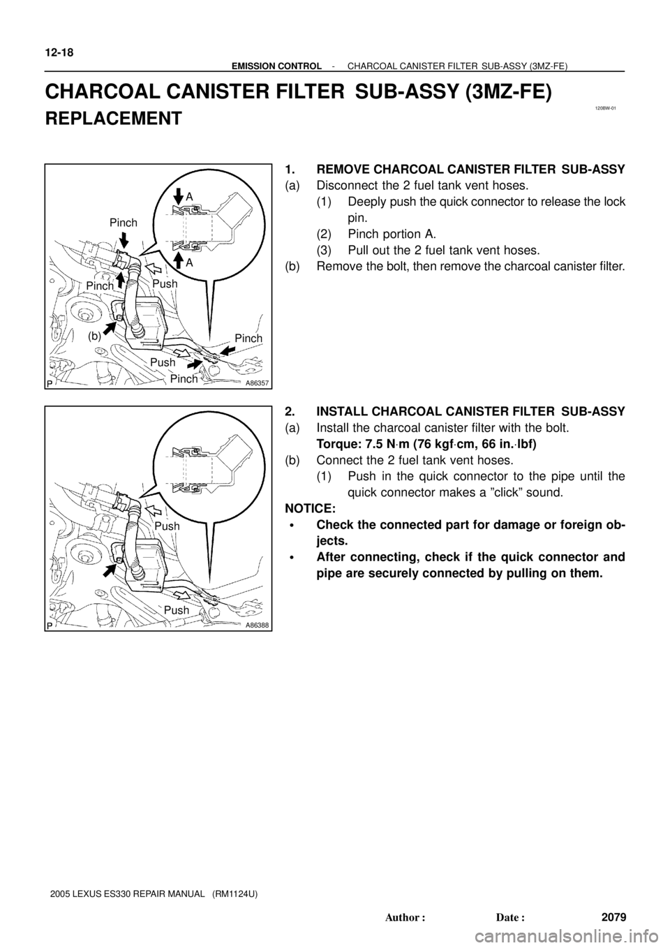
A86357
A A
Push
Pinch
Pinch
PushPinch
Pinch
(b)
A86388
Push
Push 12-18
- EMISSION CONTROLCHARCOAL CANISTER FILTER SUB-ASSY (3MZ-FE)
2079 Author�: Date�:
2005 LEXUS ES330 REPAIR MANUAL (RM1124U)
CHARCOAL CANISTER FILTER SUB-ASSY (3MZ-FE)
REPLACEMENT
1. REMOVE CHARCOAL CANISTER FILTER SUB-ASSY
(a) Disconnect the 2 fuel tank vent hoses.
(1) Deeply push the quick connector to release the lock
pin.
(2) Pinch portion A.
(3) Pull out the 2 fuel tank vent hoses.
(b) Remove the bolt, then remove the charcoal canister filter.
2. INSTALL CHARCOAL CANISTER FILTER SUB-ASSY
(a) Install the charcoal canister filter with the bolt.
Torque: 7.5 NVm (76 kgfVcm, 66 in.Vlbf)
(b) Connect the 2 fuel tank vent hoses.
(1) Push in the quick connector to the pipe until the
quick connector makes a ºclickº sound.
NOTICE:
�Check the connected part for damage or foreign ob-
jects.
�After connecting, check if the quick connector and
pipe are securely connected by pulling on them.
Page 640 of 969

13-3
2088 Author�: Date�:
2005 LEXUS ES330 REPAIR MANUAL")
A86225
Air
E
Filter
A86226
Battery E
FAir
A86227
Ohmmeter
A86228
Ohmmeter
Body
A86229
Air
E
Filter
- INTAKEINTAKE AIR CONTROL SYSTEM (3MZ-FE)
13-3
2088 Author�: Date�:
2005 LEXUS ES330 REPAIR MANUAL (RM1124U)
(d) Check the operation.
(1) Check that air flows from port E to the filter.
(2) Apply battery voltage across the terminals.
(3) Check that air flows from port E to F.
If the operation is not as specified, replace the intake air control
valve No. 3.
3. INSPECT VACUUM SWITCHING VALVE ASSY NO.1
(a) Inspect the resistance.
(1) Using an ohmmeter, measure the resistance be-
tween the terminals.
Resistance:
Tester ConnectionSpecified Condition
1 - 233 to 39W at 20�C (68�F)
If the resistance is not as specified, replace the vacuum switch-
ing valve No. 1.
(b) Check the continuity.
(1) Using an ohmmeter, check that there is no continu-
ity between each terminal and the body.
If there is continuity, replace the vacuum switching valve No. 1.
(c) Check the operation.
(1) Check that air flows from port E to the filter.
Page 643 of 969

(b)(d)
(d)
(c)
(b)
(b)
(b)
A86221
(a)
(b)
(c)
(c) 13-6
- INTAKEINTAKE AIR CONTROL VALVE ASSY NO.3 (3MZ-FE)
2091 Author�: Date�:
2005 LEXUS ES330 REPAIR MANUAL (RM1124U)
INTAKE AI")
1307Y-01
A86220
(a)
(b)(d)
(d)
(c)
(b)
(b)
(b)
A86221
(a)
(b)
(c)
(c) 13-6
- INTAKEINTAKE AIR CONTROL VALVE ASSY NO.3 (3MZ-FE)
2091 Author�: Date�:
2005 LEXUS ES330 REPAIR MANUAL (RM1124U)
INTAKE AIR CONTROL VALVE ASSY NO.3 (3MZ-FE)
REPLACEMENT
1. DISCONNECT ENGINE WIRE NO. 3 (BATTERY NEGATIVE TERMINAL)
2. REMOVE RADIATOR LOWER AIR DEFLECTOR (See page 19-5)
3. REMOVE AIR CLEANER INLET ASSY (See page 19-5)
4. REMOVE AIR CLEANER CAP SUB-ASSY
(a) Disconnect the mass air flow meter connector.
(b) Disconnect the 4 vacuum hoses.
(c) Loosen the hose clamp bolt.
(d) Loosen the 2 bolts, then remove the air cleaner cap.
(e) Remove the air cleaner filter element.
5. REMOVE INTAKE AIR CONTROL VALVE ASSY NO.3
(a) Disconnect the VSV connector.
(b) Disconnect the vacuum hose.
(c) Unfasten the 2 claws, then remove the intake air control
valve No. 3.
6. INSTALL INTAKE AIR CONTROL VALVE ASSY NO.3
7. INSTALL AIR CLEANER CAP SUB-ASSY
Torque: 5.0 NVm (51 kgfVcm, 44 in.Vlbf)
8. INSTALL AIR CLEANER INLET ASSY (See page 19-5)
9. CHECK CONNECTION OF VACUUM HOSE (See page 14-29)
10. INSTALL RADIATOR LOWER AIR DEFLECTOR
11. CONNECT ENGINE WIRE NO. 3 (BATTERY NEGATIVE TERMINAL)
Torque: 5.4 NVm (55 kgfVcm, 48 in.Vlbf)
12. SYSTEM INITIALIZATION (See page 19-15)

Air Fuel Ratio Sensor
(Bank 1 Sensor 1) Vacuum Surge Tank
VSV for EVAP
Heated Oxygen Sensor
(Ban")