Page 361 of 969

2419 Author�: Date�:
2005 LEXUS ES330 REPAIR MANUAL (RM1124U)
(b) Claw Engagement type
(1) Using")
F07391
C91598
R00764
C83851
30-16
- DRIVE SHAFT / PROPELLER SHAFTFRONT DRIVE SHAFT (From July, 2003)
2419 Author�: Date�:
2005 LEXUS ES330 REPAIR MANUAL (RM1124U)
(b) Claw Engagement type
(1) Using pliers, install the front axle inboard joint boot
LH clamp and front axle inboard joint boot LH No.2
clamp, as shown in the illustration.
35. INSPECT FRONT DRIVE SHAFT
NOTICE:
Move the drive shaft assy keeping it level.
(a) Check that there is no remarkable play in the radial direc-
tion of the outboard joint.
(b) Check that the inboard joint slides smoothly in the thrust
direction.
(c) Check that there is no remarkable play in the radial direc-
tion of the inboard joint.
(d) Check the boots for damage.
(e) Make sure that the 2 boots are on the shaft groove.
(f) Make sure that the 2 boots are not stretched or contracted
when the drive shaft is at standard length.
Drive shaft standard length: mm (in.)
LH576.9 � 2.0 (22.713 � 0.079)
RH896.4 � 2.0 (35.291 � 0.079)
36. INSTALL FRONT DRIVE SHAFT ASSY LH
(a) Install a new front drive shaft LH hole snap ring.
(b) Coat the spline of the inboard joint shaft assy with ATF.
(c) Align the shaft splines and install the drive shaft assy with
a brass bar and hammer.
NOTICE:
�Set the snap ring with the opening side facing down-
ward.
�Be careful not to damage the oil seal, boot and dust
cover.
�Move the drive shaft assy while keeping it level.
Page 362 of 969

30-17
2420 Author�: Date�:
2005 LEXUS ES330 REPAIR MANUAL (RM1124U)
37. INSTALL FRONT DRIVE SHAFT ASSY RH
(a)")
C66548
F40142
C83022
- DRIVE SHAFT / PROPELLER SHAFTFRONT DRIVE SHAFT (From July, 2003)
30-17
2420 Author�: Date�:
2005 LEXUS ES330 REPAIR MANUAL (RM1124U)
37. INSTALL FRONT DRIVE SHAFT ASSY RH
(a) Using a screwdriver, install a new bearing bracket hole
snap ring.
NOTICE:
Do not damage the oil seal and boot.
(b) Install the bolt.
Torque: 32 NVm (330 kgfVcm, 24 ftVlbf)
38. INSTALL FRONT AXLE ASSY LH
(a) Install the front drive shaft assy LH to the front axle assy LH.
NOTICE:
�Be careful not to damage the outboard joint boot.
�Be careful not to damage the speed sensor rotor.
39. INSTALL FRONT SUSPENSION ARM SUB- ASSY
LOWER NO.1 LH
(a) Install the lower ball joint to the front suspension arm sub-
assy lower with the bolt and nuts.
Torque: 75 NVm (765 kgfVcm, 55 ftVlbf)
40. INSTALL TIE ROD ASSY LH
(a) Install the tie rod end to the steering knuckle with the nut.
Torque: 49 NVm (500 kgfVcm, 36 ftVlbf)
(b) Install a new cotter pin.
NOTICE:
If the holes for the cotter pin are not aligned, tighten the nut up to 60� further.
41. INSTALL SPEED SENSOR FRONT LH
(a) Install the flexible hose and the speed sensor to the shock
absorber with the bolt and set the clip of sensor on
knuckle.
Torque: 19 NVm (192 kgfVcm, 14 ftVlbf)
NOTICE:
�Be careful not to damage the speed sensor.
�Do not twist the sensor wire when installing the speed
sensor.
Page 364 of 969

30-19
2422 Author�: Date�:
2005 LEXUS ES330 REPAIR MANUAL (RM1124U)
FRONT AXLE HUB SUB-A")
300M6-02
C91612
C83023
F40153
SST
- DRIVE SHAFT / PROPELLER SHAFTFRONT AXLE HUB SUB-ASSY LH (From July, 2003)
30-19
2422 Author�: Date�:
2005 LEXUS ES330 REPAIR MANUAL (RM1124U)
FRONT AXLE HUB SUB-ASSY LH (From July, 2003)
REPLACEMENT
HINT:
�Replace the RH side using the same procedures as for the LH side.
1. REMOVE FRONT WHEEL
2. REMOVE FRONT AXLE HUB LH NUT (SEE PAGE 30-8)
SST 09930-00010
3. DISCONNECT SPEED SENSOR FRONT LH (SEE PAGE 30-8)
4. SEPARATE FRONT DISC BRAKE CALIPER ASSY LH
(a) Remove the 2 bolts and separate the front disc brake cali-
per assy LH from the steering knuckle LH.
NOTICE:
Use a string or other device to keep the brake caliper from
hanging down by the flexible hose.
5. REMOVE FRONT DISC
6. SEPARATE TIE ROD ASSY LH (SEE PAGE 30-8)
SST 09628-6201 1
7. SEPARATE FRONT SUSPENSION ARM SUB-ASSY LOWER NO.1 LH (SEE PAGE 30-8)
8. REMOVE FRONT AXLE ASSY LH
(a) Using a plastic hammer, separate the front drive shaft
assy LH from the front axle hub sub-assy LH.
NOTICE:
Be careful not to damage the boot and speed sensor rotor.
(b) Remove the 2 bolts, nuts and steering knuckle with the
axle hub.
9. REMOVE LOWER BALL JOINT ASSY FRONT LH
(a) Remove the cotter pin and nut.
(b) Using SST, remove the lower ball joint assy front LH.
SST 09628-6201 1
Page 367 of 969

2425 Author�: Date�:
2005 LEXUS ES330 REPAIR MANUAL (RM1124U)
18. INSTALL FRONT AXL")
C83852F45465
C97690F45054
C83023
30-22
- DRIVE SHAFT / PROPELLER SHAFTFRONT AXLE HUB SUB-ASSY LH (From July, 2003)
2425 Author�: Date�:
2005 LEXUS ES330 REPAIR MANUAL (RM1124U)
18. INSTALL FRONT AXLE HUB LH HOLE SNAP RING
(a) Using snap ring pliers, install a new front axle hub LH hole
snap ring.
19. INSTALL FRONT WHEEL BEARING DUST
DEFLECTOR NO.1 LH
(a) Using SST and a hammer, install the bearing dust deflec-
tor No.1 LH.
SST 09316- 60011 (09316- 00011, 09316- 00031),
09608-32010
HINT:
Aligh the hole for the speed sensor in the bearing dust deflector
No.1 LH with the steering knuckle.
20. INSTALL LOWER BALL JOINT ASSY FRONT LH
(a) Install the lower ball joint assy front LH and tighten the nut.
Torque: 123 NVm (1,254 kgfVcm, 90 ftVlbf)
(b) Install a new cotter pin.
NOTICE:
If the holes for the cotter pin are not aligned, tighten the nut up to 60� further.
21. INSTALL FRONT AXLE ASSY LH
(a) Install the front axle assy LH with the 2 bolts and nuts to
the shock absorber assy front LH.
Torque: 210 NVm (2,141 kgfVcm, 155 ftVlbf)
NOTICE:
�Only when reusing the bolts and nuts, apply the small
amount of engine oil to the screw part of the nuts.
�Do not excessively push out the front axle assy LH.
�Be careful not to damage the outboard joint boot.
�Be careful not to damage the speed sensor rotor.
22. INSTALL FRONT SUSPENSION ARM SUB-ASSY LOWER NO.1 LH (SEE PAGE 30-8)
23. INSTALL TIE ROD ASSY LH (SEE PAGE 30-8)
24. INSTALL FRONT DISC
Page 708 of 969

26-5
2368 Author�: Date�:
2005 LEXUS ES330 REPAIR MANUAL (RM1124U)
FRO")
2605T-05
C91608
B Front:A
C91609
C Rear:
D
SA3213
A
DB
Front
C
F40165
- FRONT SUSPENSIONFRONT WHEEL ALIGNMENT (From July, 2003)
26-5
2368 Author�: Date�:
2005 LEXUS ES330 REPAIR MANUAL (RM1124U)
FRONT WHEEL ALIGNMENT (From July, 2003)
ADJUSTMENT
1. INSPECT TIRE (See page 26-5)
2. MEASURE VEHICLE HEIGHT
Vehicle height:
FrontA - B: 120 mm (4.72 in.)
RearD - C: 52 mm (2.05 in.)
Measuring points:
A: Ground clearance of front wheel center
B: Ground clearance of lower suspension arm No. 2 set bolt
center
C: Ground clearance of strut rod set bolt center
D: Ground clearance of rear wheel center
NOTICE:
Before inspecting the wheel alignment, adjust the vehicle
height to the specified value.
HINT:
Bounce the vehicle at the corners up and down to stabilize the
suspension and inspect the vehicle height.
3. INSPECT TOE-IN
Toe-in:
Toe-in
(total)A + B: 0° ± 12' (0° ± 0.2°)
C - D: 0 ± 2 mm (0 ± 0.08 in.)
If the toe-in is not within the specified value, adjust it at the rack
ends.
4. ADJUST TOE-IN
(a) Remove the rack boot set clips.
(b) Loosen the tie rod end lock nuts.
(c) Turn the right and left rack ends by an equal amount to
adjust the toe-in.
HINT:
Try to adjust the toe-in to the center of the specified value.
(d) Make sure that the lengths of the right and left rack ends
are the same.
(e) Torque the tie rod end lock nuts.
Torque: 74 N´m (755 kgf´cm, 55 ft´lbf)
(f) Place the boots on the seats and install the clips.
HINT:
Make sure that the boots are not twisted.
(g) Perform VSC system calibration. (See page 05-471)
Page 742 of 969
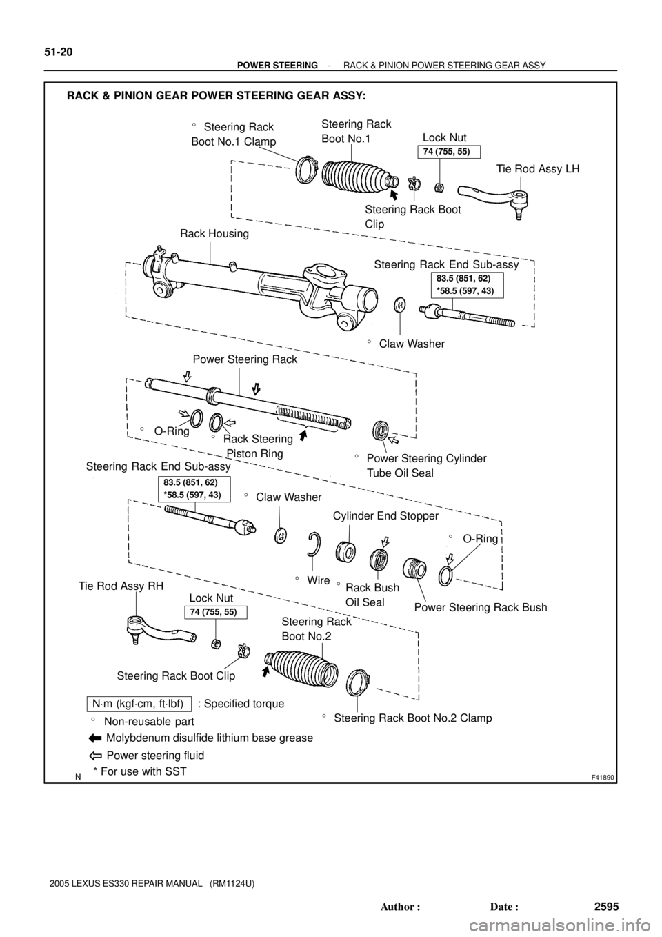
F41890
� Steering Rack
Boot No.1 ClampSteering Rack
Boot No.1
Lock Nut
Steering Rack Boot
Clip
Rack Housing
� Claw Washer
Steering Rack End Sub-assy
� Power Steering Cylinder
Tube Oil Seal
Power Steering Rack
� O-Ring� Rack Steering
Piston Ring
� O-Ring
Power Steering Rack Bush Cylinder End Stopper
� Wire
� Claw Washer
Steering Rack End Sub-assy
� Steering Rack Boot No.2 Clamp Steering Rack
Boot No.2
Steering Rack Boot ClipLock Nut
Tie Rod Assy RH
RACK & PINION GEAR POWER STEERING GEAR ASSY:
* For use with SST � Non-reusable part
NVm (kgfVcm, ftVlbf) : Specified torque
Molybdenum disulfide lithium base grease
Power steering fluid
Tie Rod Assy LH
Rack Bush
Oil Seal
�
74 (755, 55)
83.5 (851, 62)
*58.5 (597, 43)
83.5 (851, 62)
*58.5 (597, 43)
74 (755, 55)
51-20
- POWER STEERINGRACK & PINION POWER STEERING GEAR ASSY
2595 Author�: Date�:
2005 LEXUS ES330 REPAIR MANUAL (RM1124U)
Page 747 of 969
C83166
Claw
Washer
- POWER STEERINGRACK & PINION POWER STEERING GEAR ASSY
51-25
2600 Author�: Date�:
2005 LEXUS ES330 REPAIR MANUAL (RM1124U)
24. REMOVE STEERING RACK BOOT CLIP
(a) Remove the 2 steering rack boot clips.
25. REMOVE STEERING RACK BOOT NO.2 CLAMP
(a) Using pliers, remove the steering rack boot No.2 clamp.
NOTICE:
Be careful not to damage the steering rack boot No.2.
26. REMOVE STEERING RACK BOOT NO.1 CLAMP
HINT:
Remove the steering rack boot No.1 clamp by the same procedures with the steering rack boot No.2 clamp.
NOTICE:
Be careful not to damage the steering rack boot No.1.
27. REMOVE STEERING RACK BOOT NO.2
(a) Remove the steering rack boot No.2.
28. REMOVE STEERING RACK BOOT NO.1
HINT:
Remove the steering rack boot No.1 by the same procedures with the steering rack boot No.2.
29. REMOVE STEERING RACK END SUB-ASSY
(a) Using a screwdriver and a hammer, unstake the claw
washer.
NOTICE:
Avoid any impact to the power steering rack.
Page 758 of 969

50. INSPECT STEERING RACK END SUB-ASSY
(a) Ensure t")
ZX9390F41951
F40556
SST
51-36
- POWER STEERINGRACK & PINION POWER STEERING GEAR ASSY
2611 Author�: Date�:
2005 LEXUS ES330 REPAIR MANUAL (RM1124U)
50. INSPECT STEERING RACK END SUB-ASSY
(a) Ensure that the steering rack end sub-assy hole is not
clogged with grease.
HINT:
If the hole is clogged, the pressure inside the boot will change
after it is assembled and steering wheel is turned.
51. INSTALL STEERING RACK BOOT NO.2
(a) Install the steering rack boot No.2.
52. INSTALL STEERING RACK BOOT NO.1
HINT:
Remove the steering rack boot No.1 by the same procedures with steering rack boot No.2.
53. INSTALL STEERING RACK BOOT NO.2 CLAMP
(a) Using SST, tighten the steering rack boot No.2 clamp, as
shown in the illustration.
SST 09521-24010
Clearance: 3.0 mm (0.118 in.) or less
NOTICE:
Be careful not to damage the steering rack boot No.2.
54. INSTALL STEERING RACK BOOT NO.1 CLAMP
SST 09521-24010
NOTICE:
Be careful not to damage the steering rack boot No.1.
HINT:
Install the steering rack boot No.1 clamp by the same proce-
dures with steering rack boot No.2 clamp.
55. INSTALL STEERING RACK BOOT CLIP
(a) Using pliers, install the 2 steering rack boot clips.
56. INSTALL TIE ROD ASSY LH
(a) Screw the lock nut and tie rod assy LH onto the steering rack end sub-assy until the matchmarks are
aligned.
HINT:
After adjusting toe-in, torque the lock nut.
57. INSTALL TIE ROD ASSY RH
HINT:
Install the RH side by the same procedures with LH side.