Page 518 of 969
1419J-03
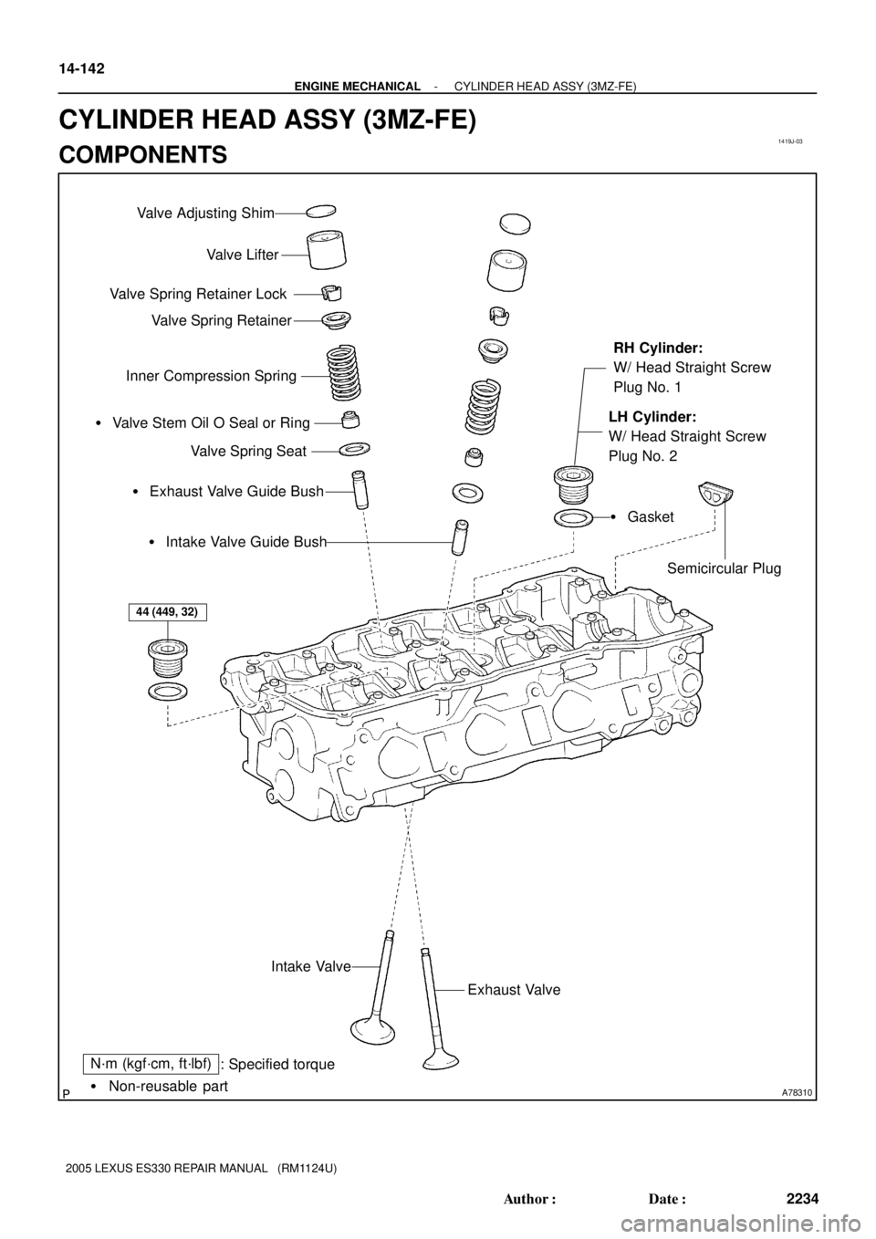
A78310� Non-reusable part
N´m (kgf´cm, ft´lbf)
: Specified torque Valve Lifter
Valve Spring Retainer Lock
Valve Spring Retainer
Inner Compression Spring
� Exhaust Valve Guide Bush � Valve Stem Oil O Seal or Ring
Valve Spring Seat
� Intake Valve Guide Bush
Exhaust Valve Intake Valve
Valve Adjusting Shim
RH Cylinder:
W/ Head Straight Screw
Plug No. 1
LH Cylinder:
W/ Head Straight Screw
Plug No. 2
� Gasket
Semicircular Plug
44 (449, 32)
14-142
- ENGINE MECHANICALCYLINDER HEAD ASSY (3MZ-FE)
2234 Author�: Date�:
2005 LEXUS ES330 REPAIR MANUAL (RM1124U)
CYLINDER HEAD ASSY (3MZ-FE)
COMPONENTS
Page 519 of 969

14-143
2235 Author�: Date�:
2005 LEXUS ES330 REPAIR MANUAL (RM1124U)
OVERHAUL
1. REMOVE W/HEAD STRAIGHT SCREW PLUG NO.1")
1419K-03
A78770
SST
A78772
SST
- ENGINE MECHANICALCYLINDER HEAD ASSY (3MZ-FE)
14-143
2235 Author�: Date�:
2005 LEXUS ES330 REPAIR MANUAL (RM1124U)
OVERHAUL
1. REMOVE W/HEAD STRAIGHT SCREW PLUG NO.1 (RH CYLINDER)
(a) Using a straight hexagon wrench 14, remove the 2 screw plugs.
2. REMOVE W/HEAD STRAIGHT SCREW PLUG NO.2 (LH CYLINDER)
(a) Using a straight hexagon wrench 14, remove the 2 screw plugs.
3. REMOVE VALVE LIFTER
HINT:
Store the lifters in the correct order so that they can be returned to the original locations when reassembling.
4. REMOVE INTAKE VALVE
(a) Using SST, compress the spring, then remove the 2 re-
tainer locks, retainer, spring and valve.
SST 09202-70020 (09202-00010)
HINT:
Store the valves, springs, seats and retainers in the correct or-
der so that they can be returned to the original locations when
reassembling.
5. REMOVE EXHAUST VALVE
(a) Using SST, compress the spring, then remove the 2 re-
tainer locks, retainer, spring and valve.
SST 09202-70020 (09202-00010)
HINT:
Store the valves, springs, seats and retainers in the correct or-
der so that they can be returned to the original locations when
reassembling.
6. REMOVE VALVE STEM OIL O SEAL OR RING
(a) Using needle-nose pliers, remove the oil seal.
7. REMOVE VALVE SPRING SEAT
8. REMOVE SEMICIRCULAR PLUG
Page 520 of 969

2236 Author�: Date�:
2005 LE")
A78773
Cylinder Block Surface:
Exhaust Manifold Surface: Intake Manifold Surface:
A05227
EM2534
Overall Length
Z00052
14-144
- ENGINE MECHANICALCYLINDER HEAD ASSY (3MZ-FE)
2236 Author�: Date�:
2005 LEXUS ES330 REPAIR MANUAL (RM1124U)
9. INSPECT CYLINDER HEAD FOR FLATNESS
(a) Using a precision straight edge and feeler gauge, mea-
sure the warpage on the surfaces which contacts the cyl-
inder block and manifolds.
Maximum warpage:
0.05 mm (0.0020 in.) for cylinder block surface
0.10 mm (0.0039 in.) for intake manifold surface
0.10 mm (0.0039 in.) for exhaust manifold surface
If the warpage is greater than maximum, replace the cylinder
head.
10. INSPECT CYLINDER HEAD FOR CRACKS
(a) Using a dye penetrate, check the combustion chamber,
intake ports, exhaust ports and cylinder block surface for
cracks.
If cracked, replace the cylinder head.
11. INSPECT INTAKE VALVE
(a) Inspect the valve overall length.
Standard overall length: 95.45 mm (3.7579 in.)
Minimum overall length: 94.95 mm (3.7382 in.)
If the overall length is less than minimum, replace the valve.
(b) Using a micrometer, measure the diameter of the valve
stem.
Valve stem diameter:
5.470 to 5.485 mm (0.2154 to 0.2159 in.)
Page 521 of 969

14-145
2237 Author�: Date�:
2005 LEXUS ES330 REPAIR MANUAL (RM112")
A78774
Margin
Thickness
EM2534
Overall Length
Z00052
A78774
Margin
Thickness
EM0801
- ENGINE MECHANICALCYLINDER HEAD ASSY (3MZ-FE)
14-145
2237 Author�: Date�:
2005 LEXUS ES330 REPAIR MANUAL (RM1124U)
(c) Inspect the valve head margin thickness.
Standard margin thickness: 1.0 mm (0.039 in.)
Minimum margin thickness: 0.5 mm (0.020 in.)
If the margin thickness is less than minimum, replace the valve.
12. INSPECT EXHAUST VALVE
(a) Inspect the valve overall length.
Standard overall length: 95.40 mm (3.7559 in.)
Minimum overall length: 94.90 mm (3.7362 in.)
If the overall length is less than minimum, replace the valve.
(b) Using a micrometer, measure the diameter of the valve
stem.
Valve stem diameter:
5.465 to 5.480 mm (0.2152 to 0.2157 in.)
(c) Inspect the valve head margin thickness.
Standard margin thickness: 1.0 mm (0.039 in.)
Minimum margin thickness: 0.5 mm (0.020 in.)
If the margin thickness is less than minimum, replace the valve.
13. INSPECT INNER COMPRESSION SPRING
(a) Using vernier calipers, measure the free length of the
spring.
Free length: 45.50 mm (1.7913 in.)
If the free length is not as specified, replace the spring.
Page 522 of 969

2238 Author�: Date�:
2005 LEXUS ES330 REPAIR MANUAL (RM1124U)
(b) Using a steel square, measure the deviat")
A78775
Deviation
EM0281
P12754
A05234
14-146
- ENGINE MECHANICALCYLINDER HEAD ASSY (3MZ-FE)
2238 Author�: Date�:
2005 LEXUS ES330 REPAIR MANUAL (RM1124U)
(b) Using a steel square, measure the deviation of the spring.
Maximum deviation: 2.0 mm (0.079 in.)
If the deviation is greater than maximum, replace the spring.
(c) Using a spring tester, measure the tension of the spring
when the spring is the specified installed length.
Installed tension:
186 to 206 N (19.0 to 21.0 kgf, 41.9 to 46.3 lbf)
at 33.8 mm (1.331 in.)
If the installed tension is not as specified, replace the spring.
14. INSPECT VALVE GUIDE BUSH OIL CLEARANCE
(a) Using a caliper gauge, measure the inside diameter of the
valve guide bush.
Bush inside diameter:
5.510 to 5.530 mm (0.2169 to 0.2177 in.)
(b) Subtract the valve stem diameter measurement from the
valve guide bush inside diameter measurement.
Standard oil clearance:
0.025 to 0.060 mm (0.0010 to 0.0024 in.) for intake
0.030 to 0.065 mm (0.0012 to 0.0026 in.) for exhaust
Maximum oil clearance:
0.08 mm (0.0031 in.) for intake
0.10 mm (0.0039 in.) for exhaust
If the clearance is greater than maximum, replace the valve and
valve guide bush.
15. REMOVE VALVE GUIDE BUSH
(a) Heat the cylinder head up to 80 to 100 �C
(176 to 212 �F).
Page 523 of 969
40.5 mm
(1.594 in.) Exhaust:
A78778
SST
Z09124
- ENGINE MECHANICALCYLINDER HEAD ASSY (3MZ-FE)
14-147
2239 Author�: Date�:
2005 LEXUS ES330 REPAIR")
A78776
SST
P12956
A78777
Intake:
34.5 mm
(1.358 in.)40.5 mm
(1.594 in.) Exhaust:
A78778
SST
Z09124
- ENGINE MECHANICALCYLINDER HEAD ASSY (3MZ-FE)
14-147
2239 Author�: Date�:
2005 LEXUS ES330 REPAIR MANUAL (RM1124U)
(b) Using SST and a hammer, tap out the valve guide bush.
SST 09201-10000, 09201-01055, 09950-70010
(09951-07100)
16. INSTALL VALVE GUIDE BUSH
(a) Using a caliper gauge, measure the bush bore diameter
of the cylinder head.
Diameter: 10.295 to 10.313 mm (0.4053 to 0.4060 in.)
If the bush bore diameter of the cylinder head is greater than
10.313 mm (0.4060 in.), machine the bush bore to the dimen-
sion of 10.345 to 10.363 mm (0.4073 to 0.4080 in.).
HINT:
Bush diameter:
STD10.333 to 10.344 mm (0.4068 to 0.4072 in.)
O/S10.383 to 10.394 mm (0.4088 to 0.4092 in.)
Bush length:
Intake34.5 mm (1.358 in.)
Exhaust40.5 mm (1.594 in.)
(b) Heat the cylinder head up to 80 to 100 �C (176 to 212 �F).
(c) Using SST and a hammer, tap in a new valve guide bush
to the specified protrusion height.
SST 09201-10000, 09201-01055, 09950-70010
(09951-07100)
Protrusion height:
11.1 to 11.5 mm (0.437 to 0.453 in.) for intake
8.9 to 9.3 mm (0.350 to 0.366 in.) for exhaust
(d) Using a sharp 5.5 mm reamer, ream the valve guide bush
to obtain the standard specified clearance between the
valve guide bush and valve stem.
Standard oil clearance:
0.025 to 0.060 mm (0.0010 to 0.0024 in.) for intake
0.030 to 0.065 mm (0.0012 to 0.0026 in.) for exhaust
Page 524 of 969
30�
A78781
45� 60�
1.0 to 1.4 mm
(0.039 to 0.055 in.)
EM6368
14-148
- ENGINE MECHANICALCYLINDER HEAD ASSY (3MZ-FE)
2240 Author�: Date�:
2005")
A78779
Width
A78780
45�
1.0 to 1.4 mm
(0.039 to 0.055 in.)30�
A78781
45� 60�
1.0 to 1.4 mm
(0.039 to 0.055 in.)
EM6368
14-148
- ENGINE MECHANICALCYLINDER HEAD ASSY (3MZ-FE)
2240 Author�: Date�:
2005 LEXUS ES330 REPAIR MANUAL (RM1124U)
17. INSPECT VALVE SEATS
(a) Apply a light coat of prussian blue (or white lead) to the
valve face.
(b) Lightly press the valve against the seat.
NOTICE:
Do not rotate the valve.
(c) Check the valve face and seat according to the following
procedure.
(1) If blue appears 360� around the face, the valve is
concentric. If not, replace the valve.
(2) If blue appears 360� around the valve seat, the
guide and face are concentric. If not, resurface the
seat.
(3) Check that the seat contact is in the middle of the
valve face with the width between 1.0 and 1.4 mm
(0.039 to 0.055 in.).
18. REPAIR VALVE SEATS
NOTICE:
Releasing the seat cutter pressure gradually helps to make
smoother valve seat faces.
(a) If the seating is too high on the valve face, use the 30� and
45� cutters to correct the seat.
(b) If the seating is too low on the valve face, use the 60� and
45� cutters to correct the seat.
(c) Lap the valve and valve seat by hand with an abrasive
compound.
(d) Recheck the valve seating position.
19. INSPECT VALVE LIFTER
(a) Using a micrometer, measure the lifter diameter.
Lifter diameter:
30.966 to 30.976 mm (1.2191 to 1.2195 in.)
Page 525 of 969

14-149
2241 Author�: Date�:
2005 LEXUS ES330 REPAIR MANUAL (RM1124U)
20. INSPECT VALVE LIFTER OIL CLEARANCE
(a) Using a caliper ga")
P12685
A33264
A05238
- ENGINE MECHANICALCYLINDER HEAD ASSY (3MZ-FE)
14-149
2241 Author�: Date�:
2005 LEXUS ES330 REPAIR MANUAL (RM1124U)
20. INSPECT VALVE LIFTER OIL CLEARANCE
(a) Using a caliper gauge, measure the lifter bore diameter
of the cylinder head.
Lifter bore diameter:
31.009 to 31.025 mm (1.2208 to 1.2215 in.)
(b) Subtract the lifter diameter measurement from the lifter
bore diameter measurement.
Standard oil clearance:
0.033 to 0.059 mm (0.0013 to 0.0023 in.)
Maximum oil clearance: 0.07 mm (0.0028 in.)
�If the oil clearance is greater than maximum, re-
place the valve lifter.
�If necessary, replace the cylinder head.
21. INSPECT CAMSHAFT GEAR BACKLASH
(a) Install the camshaft timing gear.
(b) Install the camshafts to the cylinder head.
NOTICE:
�Install the camshafts with the valves and sub gear re-
moved.
�Install the camshafts with their timing marks
matched.
(c) Set the dial indicator to the teeth of the intake camshaft
at a right angle (90�).
(d) Measure the backlash of the camshaft timing gear at least
4 positions.
Standard backlash:
0.020 to 0.200 mm (0.0008 to 0.0079 in.)
Maximum backlash: 0.30 mm (0.0118 in.)
22. INSPECT CAMSHAFT THRUST CLEARANCE
(a) Install the camshafts.
(b) Using a dial indicator, measure the thrust clearance while
moving the camshaft back and forth.
Standard thrust clearance:
0.040 to 0.090 mm (0.0016 to 0.0035 in.)
Maximum thrust clearance: 0.12 mm (0.0047 in.)
�If the thrust clearance is greater than maximum, re-
place the camshaft.
�If necessary, replace the bearing caps and cylinder
head together.
23. INSPECT CAMSHAFT OIL CLEARANCE
(a) Clean the bearing caps and camshaft journals.
(b) Clean the camshafts.
(c) Place the camshafts on the cylinder head.