Page 1977 of 3419

EM-74Revision: October 2005
CYLINDER BLOCK
2005 QX56
* Refer to GI-45, "Recommended Chemical Products and Sealants" .
DISASSEMBLY
NOTE:
Explained here is how to disassemble with engine stand supporting transmission surface. When using differ-
ent type of engine stand, note steps may be different.
1. Remove engine assembly and mount to engine stand. Refer to EM-69, "
REMOVAL" .
CAUTION:
Before removing the hanging chains, make sure engine stand is stable and there is no risk of over-
turning.
2. Drain engine oil. Refer to LU-8, "
Changing Engine Oil" .
3. Drain engine coolant by removing the cylinder block drain plugs
“A”, “B”, “C” and “D” as shown.
4. Remove the following components and associated parts (The parts referred to in step 1 are not included
here.)
�Oil pan and oil strainer. Refer to EM-22, "REMOVAL" .
�Crankshaft pulley, front cover and timing chain. Refer to EM-36, "REMOVAL" .
�Camshaft. Refer to EM-43, "REMOVAL" .
�Cylinder head. Refer to EM-59, "REMOVAL" .
5. Remove knock sensor.
CAUTION:
Carefully handle sensor, avoiding shocks.
6. Check connecting rod side clearance. Refer to EM-89, "
CONNECTING ROD SIDE CLEARANCE" .
7. Remove piston and connecting rod assembly as follows.
a. Position the crankshaft pin corresponding to the connecting rod to be removed onto bottom dead center.
b. Remove connecting rod cap.
1. Knock sensor sub-harness 2. Knock sensor 3. Cylinder block
4. Main bearing 5. Top ring 6. Second ring
7. Oil ring 8. Crankshaft key 9. Piston
10. Connecting rod 11. Snap ring 12. Piston pin
13. Connecting rod bearing 14. Connecting rod bearing cap 15. Main bearing cap
16. Thrust bearing 17. Main bearing 18. Crankshaft
19. Pilot converter 20. Thrust bearing 21. Side bolt
22. Drive plate 23. Reinforcement plate 24. Rear oil seal retainer
25. Rear oil seal 26. Transmission 27. O-ring
28. Crankshaft position sensor (POS) 29. Gasket 30. Cylinder block heater
31. Connector cap
WBIA0419E
Page 1984 of 3419
CYLINDER BLOCK
EM-81
C
D
E
F
G
H
I
J
K
L
MA
EM
Revision: October 20052005 QX56
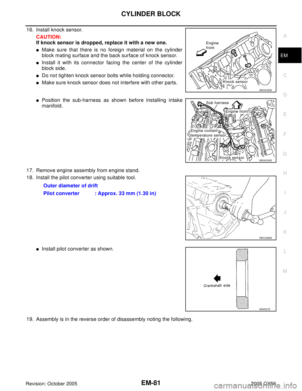
16. Install knock sensor.
CAUTION:
If knock sensor is dropped, replace it with a new one.
�Make sure that there is no foreign material on the cylinder
block mating surface and the back surface of knock sensor.
�Install it with its connector facing the center of the cylinder
block side.
�Do not tighten knock sensor bolts while holding connector.
�Make sure knock sensor does not interfere with other parts.
�Position the sub-harness as shown before installing intake
manifold.
17. Remove engine assembly from engine stand.
18. Install the pilot converter using suitable tool.
�Install pilot converter as shown.
19. Assembly is in the reverse order of disassembly noting the following.
KBIA2493E
KBIA2549E
Outer diameter of drift
Pilot converter : Approx. 33 mm (1.30 in)
PBIC0899E
SEM 53 7E
Page 2015 of 3419

EX-2Revision: October 2005
PREPARATION
2005 QX56
PREPARATIONPFP:00002
Special Service ToolEBS00M3V
The actual shapes of Kent-Moore tools may differ from those of special service tools illustrated here.
Commercial Service ToolsEBS00M3W
Tool number
(Kent-Moore No.)
Tool nameDescription
KV10114400
(J-38365)
Heated oxygen sensor wrenchLoosening or tightening heated oxygen sen-
sors:
a: 22 mm (0.87 in)
S-NT636
(Kent-Moore No.)
Tool nameDescription
a: (J-43897-18)
b: (J-43897-12)
Oxygen sensor thread cleanerReconditioning the exhaust system threads
before installing a new heated oxygen sensor
(Use with anti-seize lubricant shown below):
a: J-43897-18 (18 mm, 0.71 in) dia. for zirco-
nia oxygen sensor
b: J-43897-12 (12 mm, 0.47 in) dia. for tita-
nia oxygen sensor
Anti-seize lubricant (Permatex 133AR
or equivalent meeting MIL specifica-
tion MIL-A-907)Lubricating oxygen sensor thread cleaning
tool when reconditioning exhaust system
threads
Power toolLoosening nuts and bolts
AEM488
AEM489
PBIC0190E
Page 2016 of 3419

EXHAUST SYSTEM
EX-3
C
D
E
F
G
H
I
J
K
L
MA
EX
Revision: October 20052005 QX56
EXHAUST SYSTEMPFP:20100
Checking Exhaust SystemEBS00M3X
Check exhaust pipes, muffler and mounting for improper attachment, leaks, cracks, damage or deterioration.
�If anything is found, repair or replace damaged parts.
Removal and InstallationEBS00M3Y
Exhaust System
CAUTION:
�Be sure to use genuine exhaust system parts or equivalents which are specially designed for heat
resistance, corrosion resistance, and shape.
�Perform the operation with the exhaust system fully cooled. The system will be hot just after the
engine stops.
�Be careful not to cut your hand on the heat insulator edge.
SM A211 A
WBIA0416E
1. Tailpipe hanger bracket 2. Tailpipe 3. Gasket
4. Main muffler 5. Right front exhaust tube 6. Ring gasket
7. Heated oxygen sensor 2 (bank 2) 8. Heated oxygen sensor 2 (bank 1) 9. Left front exhaust tube
10. Center exhaust tube 11. Muffler hanger bracket front 12. Muffler hanger bracket rear
Page 2017 of 3419

EX-4Revision: October 2005
EXHAUST SYSTEM
2005 QX56
REMOVAL
Remove exhaust system components using power tool.
INSTALLATION
Installation is in the reverse order of removal.
CAUTION:
�Always replace exhaust gaskets with new ones when reassembling.
�Before installing a new heated oxygen sensor, clean and lube the exhaust tube threads using Tool.
�Discard any heated oxygen sensor which has been dropped from a height of more than 0.5 m (19.7
in) onto a hard surface such as a concrete floor; replace with a new one.
�Do not over-torque the heated oxygen sensor. Doing so may damage the heated oxygen sensor,
resulting in the MIL coming on.
�If any mounting insulator is badly deformed, repair or replace it. If deposits such as mud pile up on
the mounting insulators, clean and inspect them.
�Temporarily tighten the nuts on the exhaust manifold side and the bolts on the vehicle side. Check
each part for interference with other components, and then tighten the nuts and bolts to specifica-
tion.
INSPECTION AFTER INSTALLATION
�With the engine running, check exhaust tube joints for gas leakage and unusual noises.
�Check to ensure that mounting brackets and mounting rubbers are installed properly and free from undue
stress. Improper installation could result in excessive noise and vibration. Tool number
A : — (J-43897-18)
B : — (J-43897-12)
Page 2023 of 3419

FAX-6
WHEEL HUB
Revision: October 20052005 QX56
4. Put alignment mark on disc rotor and wheel hub and bearing
assembly, then remove disc rotor.
5. Remove cotter pin, then remove lock nut from drive shaft using power tool. Refer to FA X -7 , "
Removal and
Installation" .
6. Remove drive shaft from wheel hub and bearing assembly. Refer to FAX-7, "
Removal and Installation" .
7. Remove ABS sensor. Refer to BRC-64, "
Removal and Installation" .
�Inspect the ABS sensor O-ring, replace the ABS sensor assembly if damaged.
�Clean the ABS sensor hole and mounting surface with a suitable brake cleaner and clean lint-free shop
rag. Be careful that dirt and debris do not enter the axle bearing area.
�Apply a coat of suitable grease to the ABS sensor O-ring and mounting hole.
CAUTION:
Do not pull on the ABS sensor harness.
8. Remove wheel hub and bearing assembly bolts using power tool.
9. Remove splash guard and wheel hub and bearing assembly from steering knuckle.
INSPECTION AFTER REMOVAL
Check for deformity, cracks and damage on each part, replace if necessary.
INSTALLATION
Installation is in the reverse order of removal.
�Use new bolts when installing the wheel hub and bearing assembly.
�When installing disc rotor on wheel hub and bearing assembly,
position the disc rotor according to alignment mark.
(When not using the alignment mark, refer to BR-21, "
Removal
and Installation of Brake Caliper Assembly and Disc Rotor" .)
�When installing wheel and tire. Refer to WT-7, "Rotation" .
WDIA0044E
WDIA0044E
Page 2024 of 3419

DRIVE SHAFT
FAX-7
C
E
F
G
H
I
J
K
L
MA
B
FA X
Revision: October 20052005 QX56
DRIVE SHAFTPFP:39100
Removal and InstallationEDS001XF
REMOVAL
1. Remove wheel and tire using power tool.
2. Remove engine under cover using power tool.
3. Remove ABS sensor harness from mount on knuckle.
CAUTION:
Do not pull on ABS sensor harness.
4. Without disassembling the hydraulic lines, remove brake caliper using power tool. Reposition it aside with
wire. Refer to BR-21, "
Removal and Installation of Brake Caliper Assembly and Disc Rotor" .
NOTE:
Avoid depressing brake pedal while brake caliper is removed.
5. Remove coil spring and shock absorber assembly using power tool. Refer to FSU-10, "
Removal and
Installation" .
6. Separate upper link ball joint stud from steering knuckle using
Tool.
�Support lower link with jack.
7. Remove cotter pin, then remove drive shaft nut.
8. Remove drive shaft mounting bolts from front final drive.
9. Remove drive shaft from wheel hub and bearing assembly.
CAUTION:
�When removing drive shaft, do not apply an excessive
angle to drive shaft joint. Also be careful not to exces-
sively extend slide joint.
INSPECTION AFTER REMOVAL
�Move joint up, down, left, right, and in axial direction. Check for any rough movement or significant loose-
ness.
�Check boot for cracks or other damage, and for grease leakage.
�If damaged, disassemble drive shaft to verify damage, and
repair or replace as necessary.
1. Cotter pin 2. Drive shaft nut 3. Drive shaft
LDIA0159E
Tool number : ST29020001 (J-24319-01)
LEIA0095E
RAA0030D
Page 2066 of 3419

FL-1
FUEL SYSTEM
B ENGINE
CONTENTS
C
D
E
F
G
H
I
J
K
L
M
SECTION FL
A
FL
Revision: October 20052005 QX56 PREPARATION ........................................................... 2
Special Service Tools ............................................... 2
Commercial Service Tool ......................................... 2
FUEL SYSTEM ........................................................... 3
Checking Fuel Lines ................................................. 3
General Precautions ................................................ 3
FUEL LEVEL SENSOR UNIT, FUEL FILTER AND
FUEL PUMP ASSEMBLY ........................................... 5
Removal and Installation .......................................... 5
REMOVAL ............................................................. 5
INSTALLATION ..................................................... 8
INSPECTION AFTER INSTALLATION ................. 8FUEL TANK ................................................................ 9
Removal and Installation .......................................... 9
REMOVAL ........................................................... 10
INSTALLATION ................................................... 13
INSPECTION AFTER INSTALLATION ................ 13
SERVICE DATA AND SPECIFICATIONS (SDS) ...... 14
Standard and Limit .................................................. 14