Page 1897 of 3419

EI-36
BODY SIDE TRIM
Revision: October 20052005 QX56
Installation is in the reverse order of removal.
CENTER PILLAR LOWER FINISHER
Removal and Installation
1. Remove front and rear door welts.
2. Remove seat belt anchor. Refer to SB-3, "
Removal and Installation of Front Seat Belt" .
�On RH side, disconnect seat belt tension sensor.
3. Remove front and rear kicking plates. Refer to EI-36, "
KICKING PLATES" .
4. Remove center pillar lower finisher.
Installation is in the reverse order of removal.
CENTER PILLAR UPPER FINISHER
Removal and Installation
1. Remove center pillar lower finisher. Refer to EI-36, "CENTER PILLAR LOWER FINISHER" .
2. Remove assist grip.
3. Remove center pillar upper finisher.
Installation is in the reverse order of removal.
FRONT PILLAR FINISHER
Removal and Installation
1. Remove assist grip.
2. Remove front pillar finisher.
Installation is in the reverse order of removal.
KICKING PLATES
Removal and Installation
Release clips and remove front and/or rear kicking plates.
Installation is in the reverse order of removal.
MUDGUARD FINISHERS
Removal and Installation
Release clips and remove front and/or rear mudguard finishers.
Installation is in the reverse order of removal.
DOOR PARTING SEALS
Removal and Installation
1. Open front and/or rear doors fully.
2. Release clips and remove parting seals.
Installation is in the reverse order of removal.
Page 1908 of 3419

PREPARATION
EM-5
C
D
E
F
G
H
I
J
K
L
MA
EM
Revision: October 20052005 QX56
PREPARATIONPFP:00002
Special Service ToolsEBS00LLR
The actual shapes of Kent-Moore tools may differ from those of special service tools illustrated here.
Tool number
(Kent-Moore No.)
Tool nameDescription
KV10111100
(J-37228)
Seal cutterRemoving steel oil pan and rear timing chain
case
—
(J-44626)
Air fuel sensor SocketLoosening or tightening air fuel ratio A/F sen-
sor
a: 22 mm (0.87 in)
EG15050500
(J-45402)
Compression gauge adapterInspecting compression pressure
KV10116200
(J-26336-A)
Valve spring compressor
1. KV10115900
(J-26336-20)
Attachment
2. KV10109220
(—)
AdapterDisassembling valve mechanism
Part (1) is a component of KV10116200
(J26336-A), but part (2) is not.
KV10112100
(BT-8653-A)
Angle wrenchTightening bolts for cylinder head, main bear-
ing cap and connecting rod cap
KV10107902
(J-38959)
Valve oil seal pullerRemoving valve oil seal
S-NT046
LBIA0444E
ZZA1225D
PBIC1650E
S-NT014
S-NT011
Page 1911 of 3419
EM-8Revision: October 2005
PREPARATION
2005 QX56
Valve guide reamer 1: Reaming valve guide hole
2: Reaming hole for oversize valve guide
Intake & Exhaust:
d
1 : 6.0 mm (0.236 in) dia.
d
2 : 10.175 - 10.196 mm (0.4006 - 0.4014 in)
dia.
Front oil seal drift Installing front oil seal
Rear oil seal drift Installing rear oil seal
(J-43897-18)
(J-43897-12)
Oxygen sensor thread cleanerReconditioning the exhaust system threads
before installing a new A/F sensor and heated
oxygen sensor (Use with anti-seize lubricant
shown below.)
a: J-43897-18 (18 mm dia.) for zirconia
heated oxygen sensor
b: J-43897-12 (12 mm dia.) for titania heat-
ed oxygen sensor
Anti-seize lubricant (Permatex 133AR
or equivalent meeting MIL specifica-
tion MIL-A-907)Lubricating A/F sensors and heated oxygen
sensor thread cleaning tool when recondition-
ing exhaust system threads (Kent-Moore No.)
Tool nameDescription
S-NT016
ZZA0012D
ZZA0025D
AEM488
AEM489
Page 1922 of 3419

EXHAUST MANIFOLD AND THREE WAY CATALYST
EM-19
C
D
E
F
G
H
I
J
K
L
MA
EM
Revision: October 20052005 QX56
EXHAUST MANIFOLD AND THREE WAY CATALYSTPFP:14004
Removal and InstallationEBS00LM2
REMOVAL
WA RN ING:
Perform the work when the exhaust and cooling system have cooled sufficiently.
1. Remove the air duct and resonator assembly. Refer to EM-14, "
REMOVAL" .
2. Drain the engine coolant from the radiator. Refer to MA-13, "
DRAINING ENGINE COOLANT" .
3. Remove the engine undercover using power tool.
4. Remove the radiator and radiator hoses. Refer to CO-12, "
RADIATOR" .
5. Remove the drive belts. Refer to EM-12, "
Removal" .
6. Remove the air fuel ratio A/F sensors (right bank, left bank).
�Follow steps below to remove each air fuel ratio A/F sensor.
a. Remove the engine room cover using power tool. Refer to EM-11, "
REMOVAL" .
b. Remove the harness connector of each air fuel ratio A/F sensor, and harness from bracket and middle
clamp.
1. Air fuel ratio (A/F) sensor 1 (bank 2) 2. Exhaust manifold cover (bank 2) 3. Exhaust manifold (bank 2)
4. Gaskets 5. Exhaust manifold (left bank 1) 6. Exhaust manifold cover (bank 1)
7. Air fuel ratio (A/F) sensor 1 (bank 1)
WBIA0466E
Page 1923 of 3419

EM-20Revision: October 2005
EXHAUST MANIFOLD AND THREE WAY CATALYST
2005 QX56
c. Remove the air fuel ratio A/F sensors from both left and right
exhaust manifolds using Tool.
CAUTION:
�Be careful not to damage the air fuel ratio A/F sensors
�Discard any air fuel ratio A/F sensor which has been
dropped from a height of more than 0.5m (19.7 in) onto a
hard surface such as a concrete floor. Replace it with a
new one.
7. Remove the front cross bar.
8. Remove the exhaust manifold (left bank) following the steps
below.
a. Remove the exhaust front tube. Refer to EX-3, "
Removal and
Installation" .
b. Remove the exhaust manifold cover.
c. Loosen the nuts in reverse order of illustration using power tool.
d. Remove the exhaust studs from positions 2, 4, 6, 8 and remove
left exhaust manifold
9. Remove the exhaust manifold (right bank) following the steps
below.
a. Remove the exhaust front tube. Refer to EX-3, "
Removal and
Installation" .
b. Remove the oil level gauge guide. Refer to EM-22, "
OIL PAN
AND OIL STRAINER" .
c. Remove the exhaust manifold cover.
d. Loosen the nuts in reverse order of illustration using power tool.
e. Remove the exhaust studs from positions 2, 4, 6, 8 and remove right exhaust manifold.
INSPECTION AFTER REMOVAL
Surface Distortion
�Check the flatness of each exhaust manifold flange surface
using suitable tools.
�If measurement exceeds the limit, replace the exhaust manifold.
INSTALLATION
Installation is in the reverse order of removal.
�Install new exhaust manifold gasket with the top of the triangular
up mark on it facing up and its coated face (gray side) toward
the exhaust manifold side.Tool number : — (J-44626)
WBIA0630E
KBIA2464E
Flatness limit : 0.3 mm (0.012 in)
KBIA2504E
KBIA2553E
Page 1924 of 3419
EXHAUST MANIFOLD AND THREE WAY CATALYST
EM-21
C
D
E
F
G
H
I
J
K
L
MA
EM
Revision: October 20052005 QX56
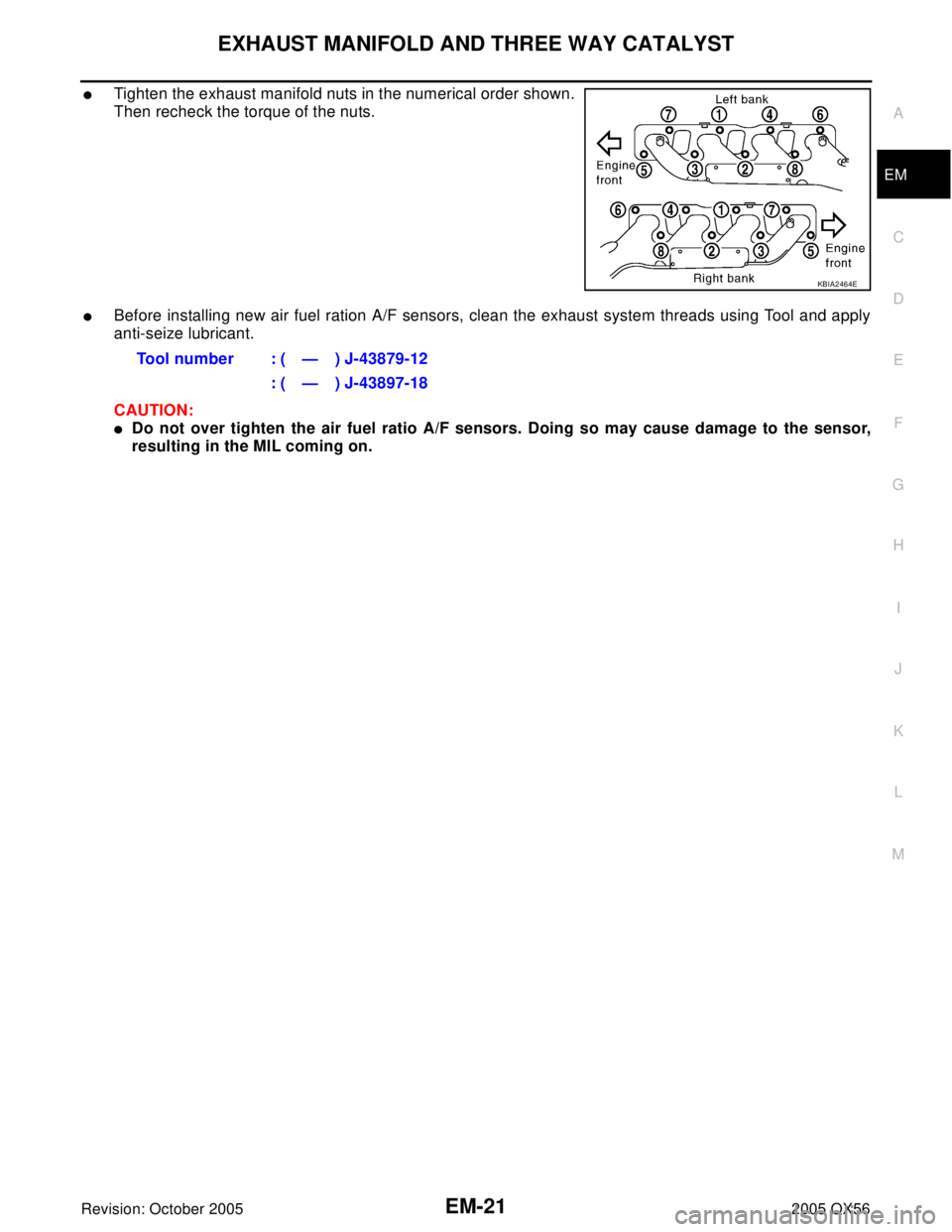
�Tighten the exhaust manifold nuts in the numerical order shown.
Then recheck the torque of the nuts.
�Before installing new air fuel ration A/F sensors, clean the exhaust system threads using Tool and apply
anti-seize lubricant.
CAUTION:
�Do not over tighten the air fuel ratio A/F sensors. Doing so may cause damage to the sensor,
resulting in the MIL coming on.
KBIA2464E
Tool number : ( — ) J-43879-12
: ( — ) J-43897-18
Page 1946 of 3419

CAMSHAFT
EM-43
C
D
E
F
G
H
I
J
K
L
MA
EM
Revision: October 20052005 QX56
CAMSHAFTPFP:13001
Removal and InstallationEBS00LM9
* Refer to GI-45, "Recommended Chemical Products and Sealants" .
REMOVAL
1. Remove the rocker cover (right bank) and (left bank). Refer to EM-33, "ROCKER COVER" .
2. Obtain compression TDC of No. 1 cylinder. Refer to EM-35, "
TIMING CHAIN" .
3. Remove the chain case cover (right bank) and (left bank). Refer to EM-35, "
TIMING CHAIN" .
4. Paint matching marks on the timing chain links aligning with the
camshaft sprocket matching marks.
1. Cylinder head (right bank) 2. Camshaft bracket (No. 2, 3, 4, 5) 3. Valve lifter
4. Camshaft bracket (No. 1) 5. Seal washer 6. Camshaft (right bank EXH)
7. Camshaft (right bank INT) 8. Camshaft (left bank INT) 9. Camshaft (left bank EXH)
10. Camshaft sprocket (right bank EXH) 11. Camshaft sprocket (right bank INT) 12. Camshaft sprocket (left bank INT)
13. Camshaft sprocket (left bank EXH) 14. Camshaft position sensor (PHASE) 15. O-ring
16. Cylinder head (left bank)
WBIA0469E
KBIA2488E
Page 1962 of 3419

CYLINDER HEAD
EM-59
C
D
E
F
G
H
I
J
K
L
MA
EM
Revision: October 20052005 QX56
Removal and InstallationEBS00LMF
REMOVAL
1. Remove the engine assembly from the vehicle. Refer to EM-69, "REMOVAL" .
2. Remove the following components and related parts:
�Auto tensioner of drive belts and idler pulley. Refer to EM-12, "DRIVE BELTS" .
�Thermostat housing and hose. Refer to CO-19, "Removal of Thermostat Housing, Water Outlet and
Heater Pipe" .
�Oil pan and oil strainer. Refer to EM-22, "OIL PAN AND OIL STRAINER" .
�Fuel tube and fuel injector assembly. Refer to EM-29, "FUEL INJECTOR AND FUEL TUBE" .
�Intake manifold. Refer to EM-15, "INTAKE MANIFOLD" .
�Ignition coil. Refer to EM-26, "IGNITION COIL" .
�Rocker cover. Refer to EM-33, "ROCKER COVER" .
3. Remove the crankshaft pulley, front cover, oil pump, and timing chain. Refer to EM-35, "
TIMING CHAIN" .
4. Remove the camshaft sprockets and camshafts. Refer to EM-43, "
CAMSHAFT" .
5. Remove the cylinder head bolts in reverse of order shown.
1. Harness bracket 2. Engine coolant temperature sensor 3. Washer
4. Cylinder head gasket (left bank) 5. Cylinder head (right bank) 6. Cylinder head bolt
7. Cylinder head gasket (right bank) 8. Cylinder head (left bank)
KBIA2528E
PBIC0068E
 dia.
d
2 : 10.175 -")