Page 2211 of 3419
GW-56
POWER WINDOW SYSTEM
Revision: October 20052005 QX56
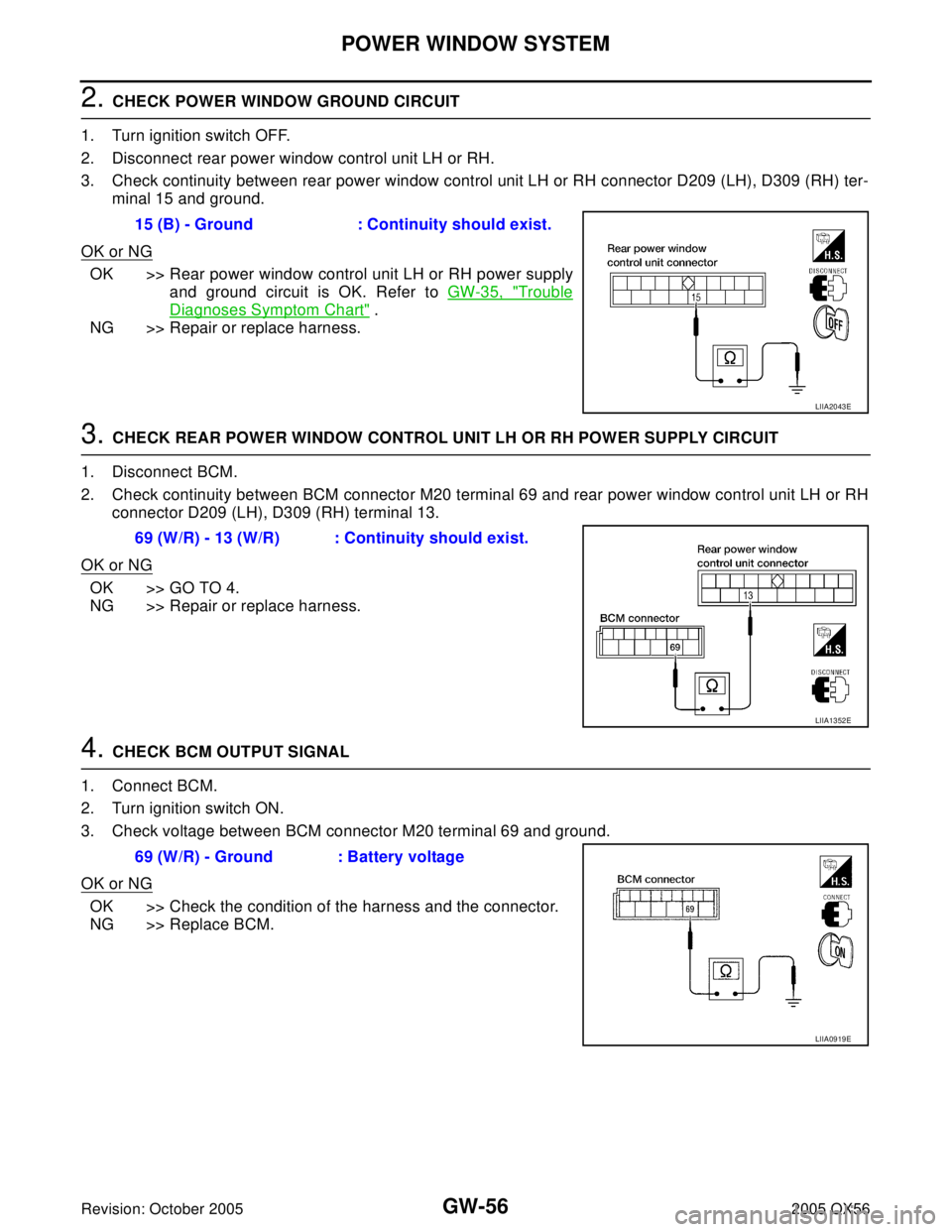
2. CHECK POWER WINDOW GROUND CIRCUIT
1. Turn ignition switch OFF.
2. Disconnect rear power window control unit LH or RH.
3. Check continuity between rear power window control unit LH or RH connector D209 (LH), D309 (RH) ter-
minal 15 and ground.
OK or NG
OK >> Rear power window control unit LH or RH power supply
and ground circuit is OK. Refer to GW-35, "
Trouble
Diagnoses Symptom Chart" .
NG >> Repair or replace harness.
3. CHECK REAR POWER WINDOW CONTROL UNIT LH OR RH POWER SUPPLY CIRCUIT
1. Disconnect BCM.
2. Check continuity between BCM connector M20 terminal 69 and rear power window control unit LH or RH
connector D209 (LH), D309 (RH) terminal 13.
OK or NG
OK >> GO TO 4.
NG >> Repair or replace harness.
4. CHECK BCM OUTPUT SIGNAL
1. Connect BCM.
2. Turn ignition switch ON.
3. Check voltage between BCM connector M20 terminal 69 and ground.
OK or NG
OK >> Check the condition of the harness and the connector.
NG >> Replace BCM.15 (B) - Ground : Continuity should exist.
LIIA2043E
69 (W/R) - 13 (W/R) : Continuity should exist.
LIIA1352E
69 (W/R) - Ground : Battery voltage
LIIA0919E
Page 2212 of 3419
POWER WINDOW SYSTEM
GW-57
C
D
E
F
G
H
J
K
L
MA
B
GW
Revision: October 20052005 QX56
Rear Power Window Switch LH or RH Power Supply and Ground Circuit CheckEIS005YB
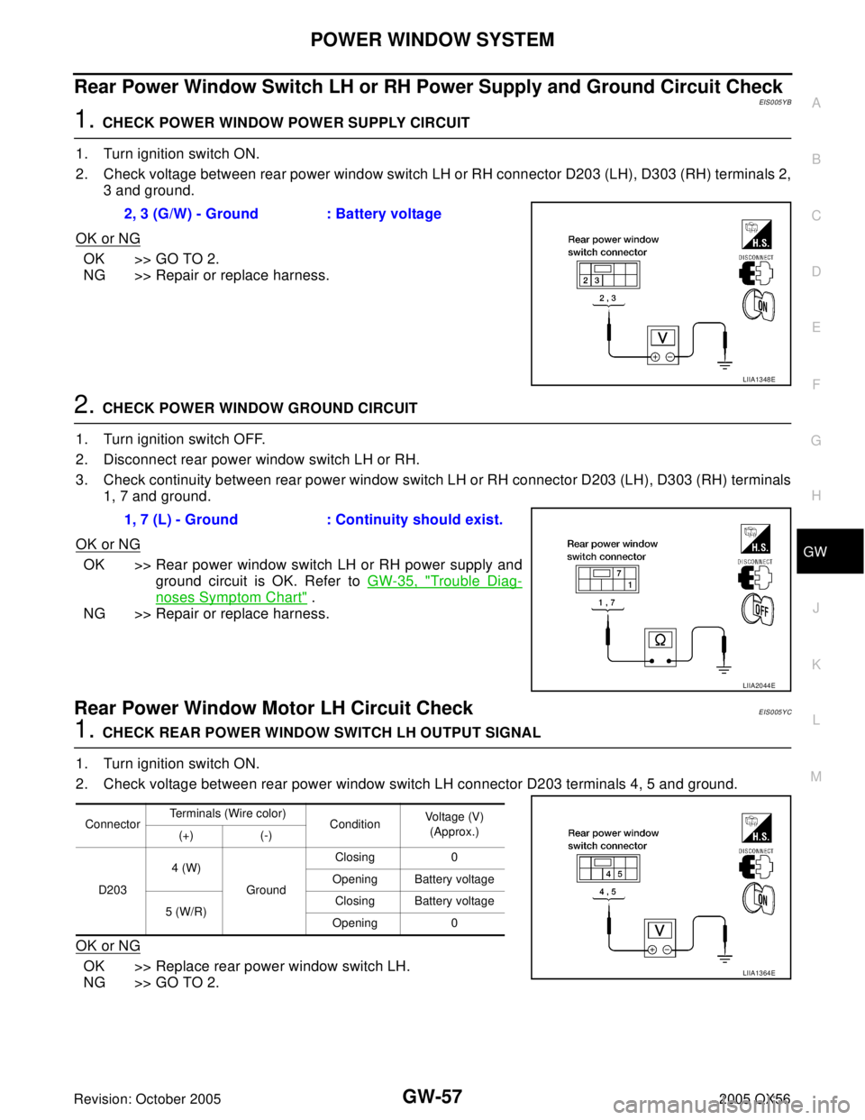
1. CHECK POWER WINDOW POWER SUPPLY CIRCUIT
1. Turn ignition switch ON.
2. Check voltage between rear power window switch LH or RH connector D203 (LH), D303 (RH) terminals 2,
3 and ground.
OK or NG
OK >> GO TO 2.
NG >> Repair or replace harness.
2. CHECK POWER WINDOW GROUND CIRCUIT
1. Turn ignition switch OFF.
2. Disconnect rear power window switch LH or RH.
3. Check continuity between rear power window switch LH or RH connector D203 (LH), D303 (RH) terminals
1, 7 and ground.
OK or NG
OK >> Rear power window switch LH or RH power supply and
ground circuit is OK. Refer to GW-35, "
Trouble Diag-
noses Symptom Chart" .
NG >> Repair or replace harness.
Rear Power Window Motor LH Circuit Check EIS005YC
1. CHECK REAR POWER WINDOW SWITCH LH OUTPUT SIGNAL
1. Turn ignition switch ON.
2. Check voltage between rear power window switch LH connector D203 terminals 4, 5 and ground.
OK or NG
OK >> Replace rear power window switch LH.
NG >> GO TO 2.2, 3 (G/W) - Ground : Battery voltage
LIIA1348E
1, 7 (L) - Ground : Continuity should exist.
LIIA2044E
ConnectorTerminals (Wire color)
ConditionVoltage (V)
(Approx.)
(+) (-)
D2034 (W)
GroundClosing 0
Opening Battery voltage
5 (W/R)Closing Battery voltage
Opening 0
LIIA1364E
Page 2213 of 3419

GW-58
POWER WINDOW SYSTEM
Revision: October 20052005 QX56
2. CHECK REAR POWER WINDOW SWITCH LH CIRCUIT
1. Turn ignition switch OFF.
2. Disconnect rear power window switch LH and rear power window control unit LH.
3. Check continuity between rear power window switch LH connector D203 terminals 4, 5 and rear power
window control unit LH connector D209 terminals 9, 10.
OK or NG
OK >> GO TO 3.
NG >> Repair or replace harness.
3. CHECK REAR POWER WINDOW MOTOR LH CIRCUIT
1. Turn ignition switch OFF.
2. Disconnect rear power window control unit LH and rear power window motor LH.
3. Check continuity between rear power window control unit LH connector D209 terminals 11, 12 and rear
power window motor LH connector D204 terminals 1, 2.
OK or NG
OK >> Replace rear power window motor LH.
NG >> Repair or replace harness.
Rear Power Window Motor RH Circuit Check EIS005YD
1. CHECK REAR POWER WINDOW SWITCH RH OUTPUT SIGNAL
1. Turn ignition switch ON.
2. Check voltage between rear power window switch RH connector D303 terminals 4, 5 and ground.
OK or NG
OK >> Replace rear power window switch RH.
NG >> GO TO 2.4 (W) - 9 (W) : Continuity should exist.
5 (W/R) - 10 (W/R) : Continuity should exist.
LIIA1379E
11 (O) - 2 (O) : Continuity should exist.
12 (BR) - 1 (BR) : Continuity should exist.
LIIA1380E
ConnectorTerminals (Wire color)
ConditionVoltage (V)
(Approx.)
(+) (-)
D3034 (W)
GroundClosing 0
Opening Battery voltage
5 (W/L)Closing Battery voltage
Opening 0
LIIA1364E
Page 2214 of 3419
POWER WINDOW SYSTEM
GW-59
C
D
E
F
G
H
J
K
L
MA
B
GW
Revision: October 20052005 QX56
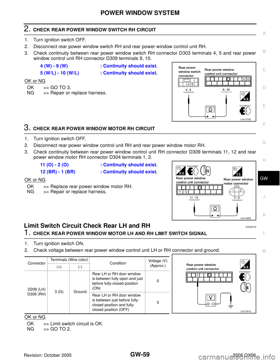
2. CHECK REAR POWER WINDOW SWITCH RH CIRCUIT
1. Turn ignition switch OFF.
2. Disconnect rear power window switch RH and rear power window control unit RH.
3. Check continuity between rear power window switch RH connector D303 terminals 4, 5 and rear power
window control unit RH connector D309 terminals 9, 10.
OK or NG
OK >> GO TO 3.
NG >> Repair or replace harness.
3. CHECK REAR POWER WINDOW MOTOR RH CIRCUIT
1. Turn ignition switch OFF.
2. Disconnect rear power window control unit RH and rear power window motor RH.
3. Check continuity between rear power window control unit RH connector D309 terminals 11, 12 and rear
power window motor RH connector D304 terminals 1, 2.
OK or NG
OK >> Replace rear power window motor RH.
NG >> Repair or replace harness.
Limit Switch Circuit Check Rear LH and RHEIS005YE
1. CHECK REAR POWER WINDOW MOTOR LH AND RH LIMIT SWITCH SIGNAL
1. Turn ignition switch ON.
2. Check voltage between rear power window control unit LH or RH connector and ground.
OK or NG
OK >> Limit switch circuit is OK.
NG >> GO TO 2.4 (W) - 9 (W) : Continuity should exist.
5 (W/L) - 10 (W/L) : Continuity should exist.
LIIA1379E
11 (O) - 2 (O) : Continuity should exist.
12 (BR) - 1 (BR) : Continuity should exist.
LIIA1380E
ConnectorTerminals (Wire color)
Condition Voltage (V)
(Approx.)
(+) (-)
D209 (LH)
D309 (RH)3 (G) GroundRear LH or RH door window
is between fully-open and just
before fully-closed position
(ON)0
Rear LH or RH door window
is between just before fully-
closed position and fully-
closed position (OFF)5
LIIA1381E
Page 2215 of 3419
GW-60
POWER WINDOW SYSTEM
Revision: October 20052005 QX56
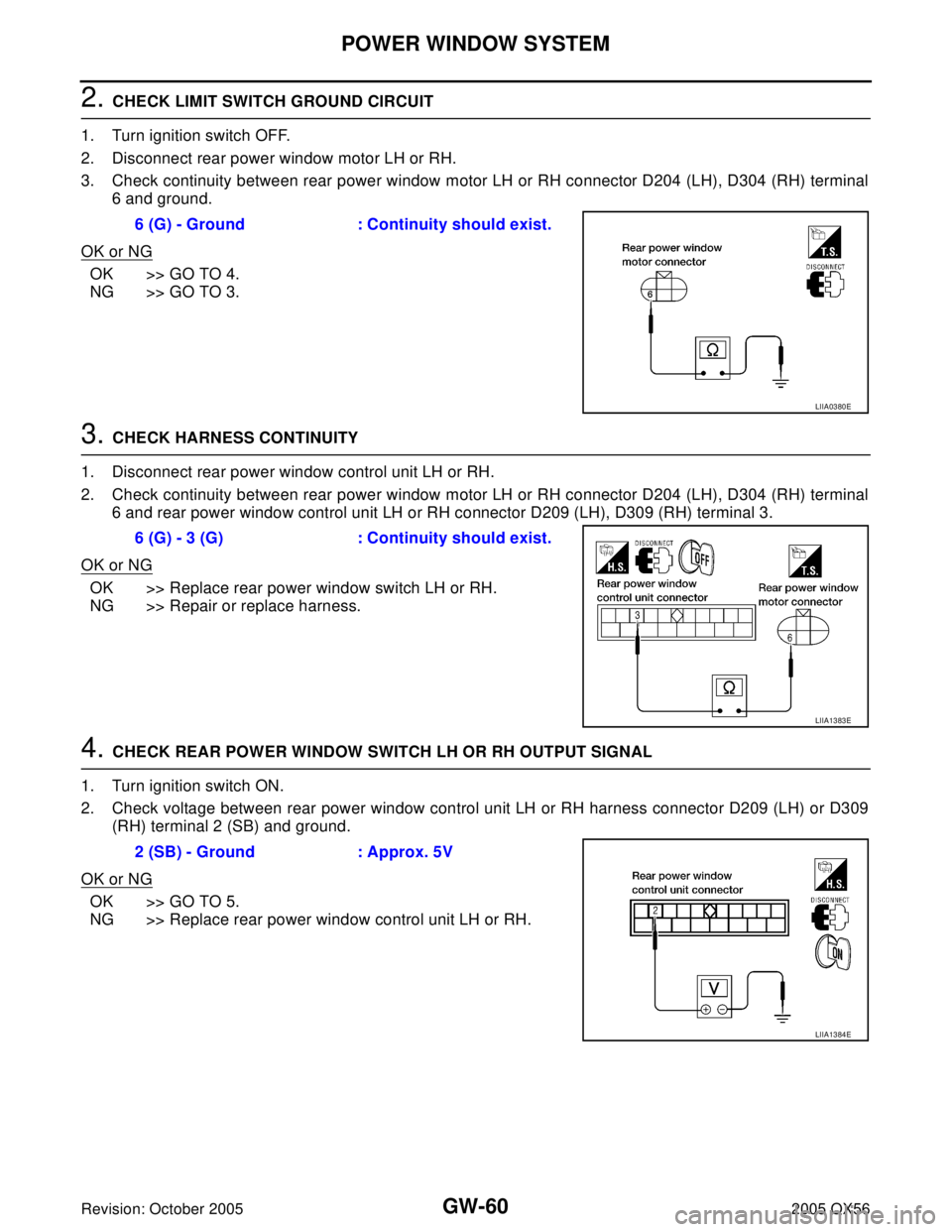
2. CHECK LIMIT SWITCH GROUND CIRCUIT
1. Turn ignition switch OFF.
2. Disconnect rear power window motor LH or RH.
3. Check continuity between rear power window motor LH or RH connector D204 (LH), D304 (RH) terminal
6 and ground.
OK or NG
OK >> GO TO 4.
NG >> GO TO 3.
3. CHECK HARNESS CONTINUITY
1. Disconnect rear power window control unit LH or RH.
2. Check continuity between rear power window motor LH or RH connector D204 (LH), D304 (RH) terminal
6 and rear power window control unit LH or RH connector D209 (LH), D309 (RH) terminal 3.
OK or NG
OK >> Replace rear power window switch LH or RH.
NG >> Repair or replace harness.
4. CHECK REAR POWER WINDOW SWITCH LH OR RH OUTPUT SIGNAL
1. Turn ignition switch ON.
2. Check voltage between rear power window control unit LH or RH harness connector D209 (LH) or D309
(RH) terminal 2 (SB) and ground.
OK or NG
OK >> GO TO 5.
NG >> Replace rear power window control unit LH or RH.6 (G) - Ground : Continuity should exist.
LIIA0380E
6 (G) - 3 (G) : Continuity should exist.
LIIA1383E
2 (SB) - Ground : Approx. 5V
LIIA1384E
Page 2217 of 3419
GW-62
POWER WINDOW SYSTEM
Revision: October 20052005 QX56
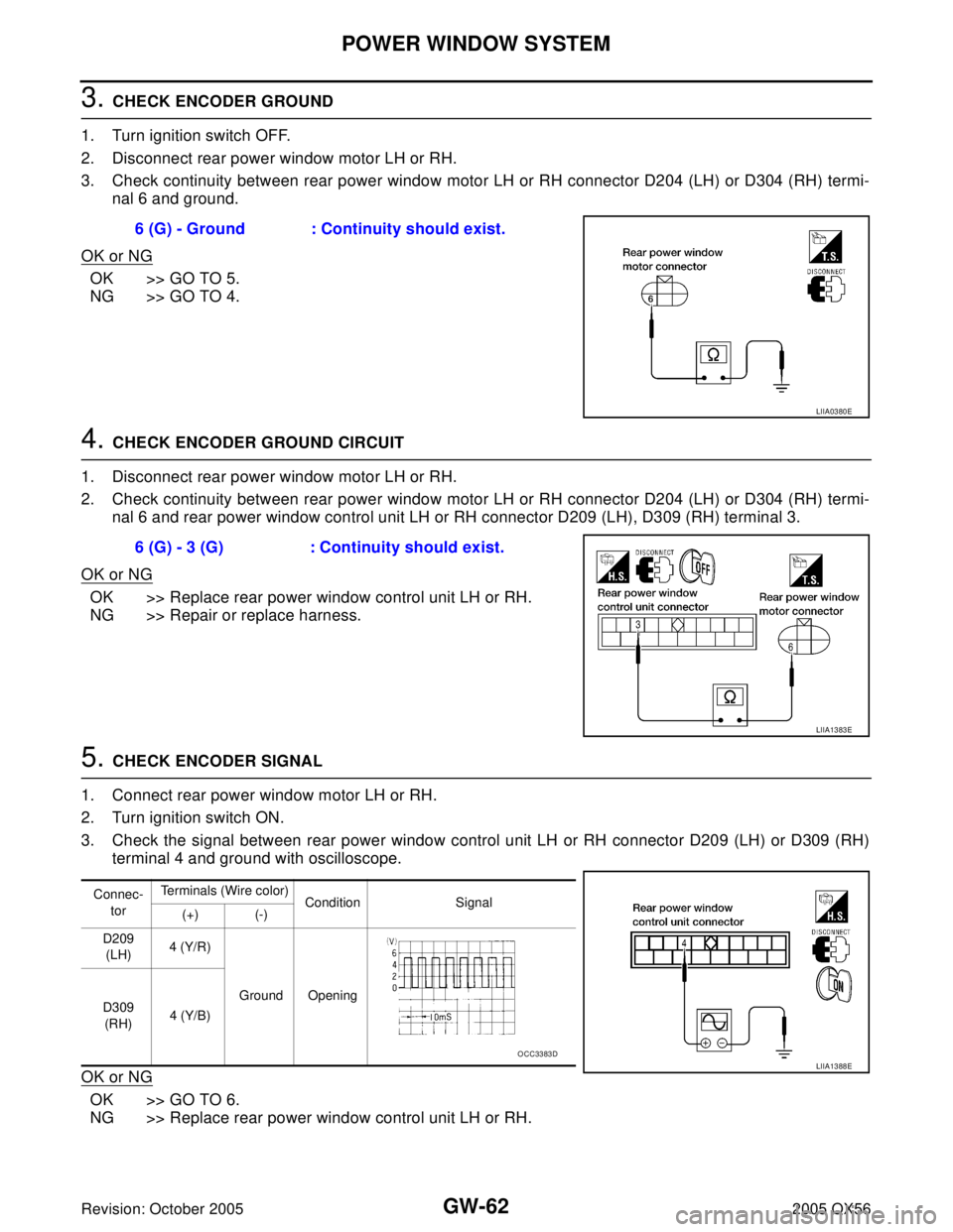
3. CHECK ENCODER GROUND
1. Turn ignition switch OFF.
2. Disconnect rear power window motor LH or RH.
3. Check continuity between rear power window motor LH or RH connector D204 (LH) or D304 (RH) termi-
nal 6 and ground.
OK or NG
OK >> GO TO 5.
NG >> GO TO 4.
4. CHECK ENCODER GROUND CIRCUIT
1. Disconnect rear power window motor LH or RH.
2. Check continuity between rear power window motor LH or RH connector D204 (LH) or D304 (RH) termi-
nal 6 and rear power window control unit LH or RH connector D209 (LH), D309 (RH) terminal 3.
OK or NG
OK >> Replace rear power window control unit LH or RH.
NG >> Repair or replace harness.
5. CHECK ENCODER SIGNAL
1. Connect rear power window motor LH or RH.
2. Turn ignition switch ON.
3. Check the signal between rear power window control unit LH or RH connector D209 (LH) or D309 (RH)
terminal 4 and ground with oscilloscope.
OK or NG
OK >> GO TO 6.
NG >> Replace rear power window control unit LH or RH.6 (G) - Ground : Continuity should exist.
LIIA0380E
6 (G) - 3 (G) : Continuity should exist.
LIIA1383E
Connec-
torTerminals (Wire color)
Condition Signal
(+) (-)
D209
(LH)4 (Y/R)
Ground Opening
D309
(RH)4 (Y/B)
LIIA1388EOCC3383D
Page 2219 of 3419
GW-64
POWER WINDOW SYSTEM
Revision: October 20052005 QX56
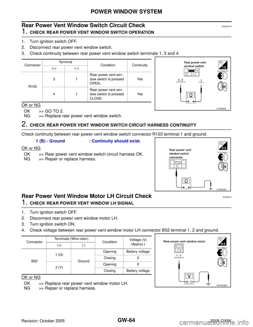
Rear Power Vent Window Switch Circuit CheckEIS005YH
1. CHECK REAR POWER VENT WINDOW SWITCH OPERATION
1. Turn ignition switch OFF.
2. Disconnect rear power vent window switch.
3. Check continuity between rear power vent window switch terminals 1, 3 and 4.
OK or NG
OK >> GO TO 2.
NG >> Replace rear power vent window switch.
2. CHECK REAR POWER VENT WINDOW SWITCH CIRCUIT HARNESS CONTINUITY
Check continuity between rear power vent window switch connector R103 terminal 1 and ground.
OK or NG
OK >> Rear power vent window switch circuit harness OK.
NG >> Repair or replace harness.
Rear Power Vent Window Motor LH Circuit CheckEIS005YI
1. CHECK REAR POWER VENT WINDOW LH SIGNAL
1. Turn ignition switch OFF.
2. Disconnect rear power vent window motor LH.
3. Turn ignition switch ON.
4. Check voltage between rear power vent window motor LH connector B52 terminal 1, 2 and ground.
OK or NG
OK >> Replace rear power vent window motor LH.
NG >> Repair or replace harness.
ConnectorTe r m i n a l
Condition Continuity
(+) (–)
R10331Rear power vent win-
dow switch is pressed
OPEN.Ye s
41Rear power vent win-
dow switch is pressed
CLOSE.Ye s
LIIA0956E
1 (B) - Ground : Continuity should exist.
LIIA2045E
ConnectorTerminals (Wire color)
ConditionVoltage (V)
(Approx.)
(+) (-)
B521 (G)
GroundOpening Battery voltage
Closing 0
2 (Y)Opening 0
Closing Battery voltage
WIIA0290E
Page 2220 of 3419
POWER WINDOW SYSTEM
GW-65
C
D
E
F
G
H
J
K
L
MA
B
GW
Revision: October 20052005 QX56
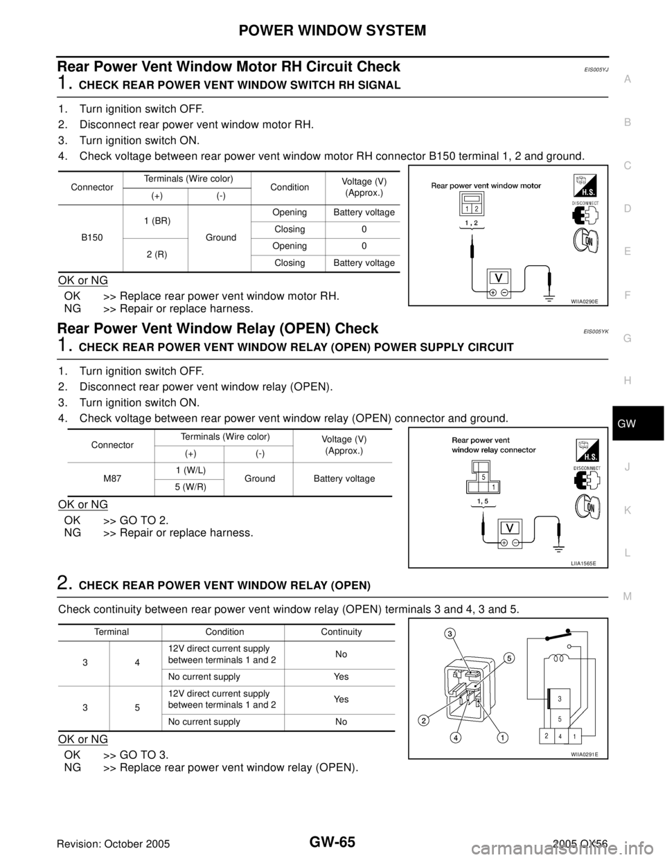
Rear Power Vent Window Motor RH Circuit CheckEIS005YJ
1. CHECK REAR POWER VENT WINDOW SWITCH RH SIGNAL
1. Turn ignition switch OFF.
2. Disconnect rear power vent window motor RH.
3. Turn ignition switch ON.
4. Check voltage between rear power vent window motor RH connector B150 terminal 1, 2 and ground.
OK or NG
OK >> Replace rear power vent window motor RH.
NG >> Repair or replace harness.
Rear Power Vent Window Relay (OPEN) CheckEIS005YK
1. CHECK REAR POWER VENT WINDOW RELAY (OPEN) POWER SUPPLY CIRCUIT
1. Turn ignition switch OFF.
2. Disconnect rear power vent window relay (OPEN).
3. Turn ignition switch ON.
4. Check voltage between rear power vent window relay (OPEN) connector and ground.
OK or NG
OK >> GO TO 2.
NG >> Repair or replace harness.
2. CHECK REAR POWER VENT WINDOW RELAY (OPEN)
Check continuity between rear power vent window relay (OPEN) terminals 3 and 4, 3 and 5.
OK or NG
OK >> GO TO 3.
NG >> Replace rear power vent window relay (OPEN).
ConnectorTerminals (Wire color)
ConditionVoltage (V)
(Approx.)
(+) (-)
B1501 (BR)
GroundOpening Battery voltage
Closing 0
2 (R)Opening 0
Closing Battery voltage
WIIA0290E
ConnectorTerminals (Wire color)
Voltage (V)
(Approx.)
(+) (-)
M871 (W/L)
Ground Battery voltage
5 (W/R)
LIIA1565E
Terminal Condition Continuity
3412V direct current supply
between terminals 1 and 2No
No current supply Yes
3512V direct current supply
between terminals 1 and 2Ye s
No current supply No
WIIA0291E