Page 1230 of 3419
ON BOARD REFUELING VAPOR RECOVERY (ORVR)
EC-39
C
D
E
F
G
H
I
J
K
L
MA
EC
Revision: October 20052005 QX56
ON BOARD REFUELING VAPOR RECOVERY (ORVR)PFP:00032
System DescriptionUBS00KZJ
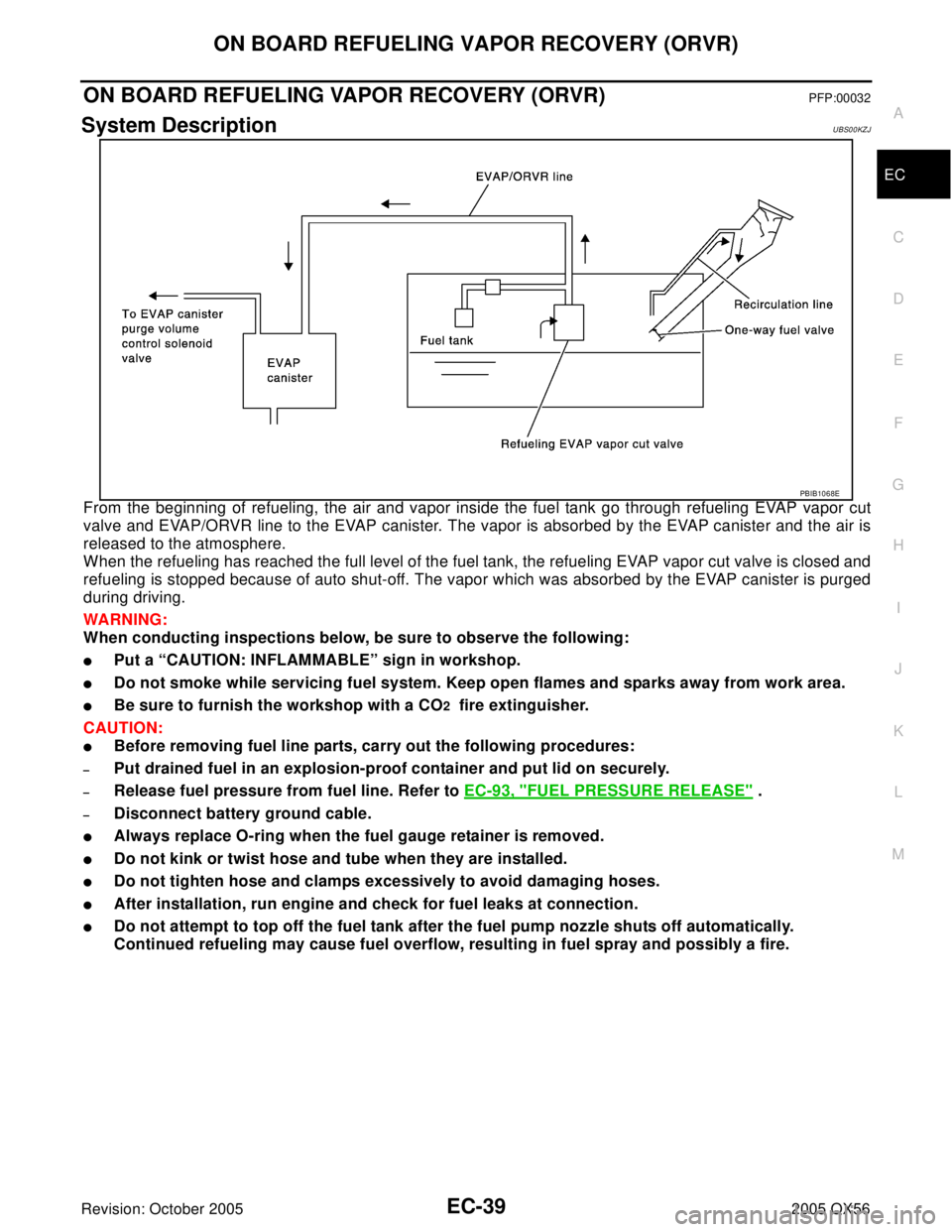
From the beginning of refueling, the air and vapor inside the fuel tank go through refueling EVAP vapor cut
valve and EVAP/ORVR line to the EVAP canister. The vapor is absorbed by the EVAP canister and the air is
released to the atmosphere.
When the refueling has reached the full level of the fuel tank, the refueling EVAP vapor cut valve is closed and
refueling is stopped because of auto shut-off. The vapor which was absorbed by the EVAP canister is purged
during driving.
WA RN ING:
When conducting inspections below, be sure to observe the following:
�Put a “CAUTION: INFLAMMABLE” sign in workshop.
�Do not smoke while servicing fuel system. Keep open flames and sparks away from work area.
�Be sure to furnish the workshop with a CO2 fire extinguisher.
CAUTION:
�Before removing fuel line parts, carry out the following procedures:
–Put drained fuel in an explosion-proof container and put lid on securely.
–Release fuel pressure from fuel line. Refer to EC-93, "FUEL PRESSURE RELEASE" .
–Disconnect battery ground cable.
�Always replace O-ring when the fuel gauge retainer is removed.
�Do not kink or twist hose and tube when they are installed.
�Do not tighten hose and clamps excessively to avoid damaging hoses.
�After installation, run engine and check for fuel leaks at connection.
�Do not attempt to top off the fuel tank after the fuel pump nozzle shuts off automatically.
Continued refueling may cause fuel overflow, resulting in fuel spray and possibly a fire.
PBIB1068E
Page 1231 of 3419
EC-40Revision: October 2005
ON BOARD REFUELING VAPOR RECOVERY (ORVR)
2005 QX56
Diagnostic ProcedureUBS00KZK
SYMPTOM: FUEL ODOR FROM EVAP CANISTER IS STRONG.
1. CHECK EVAP CANISTER
1. Remove EVAP canister with EVAP canister vent control valve and EVAP control system pressure sensor
attached.
2. Weigh the EVAP canister with EVAP canister vent control valve and EVAP control system pressure sensor
attached.
The weight should be less than 2.5 kg (5.5 lb).
OK or NG
OK >> GO TO 2.
NG >> GO TO 3.
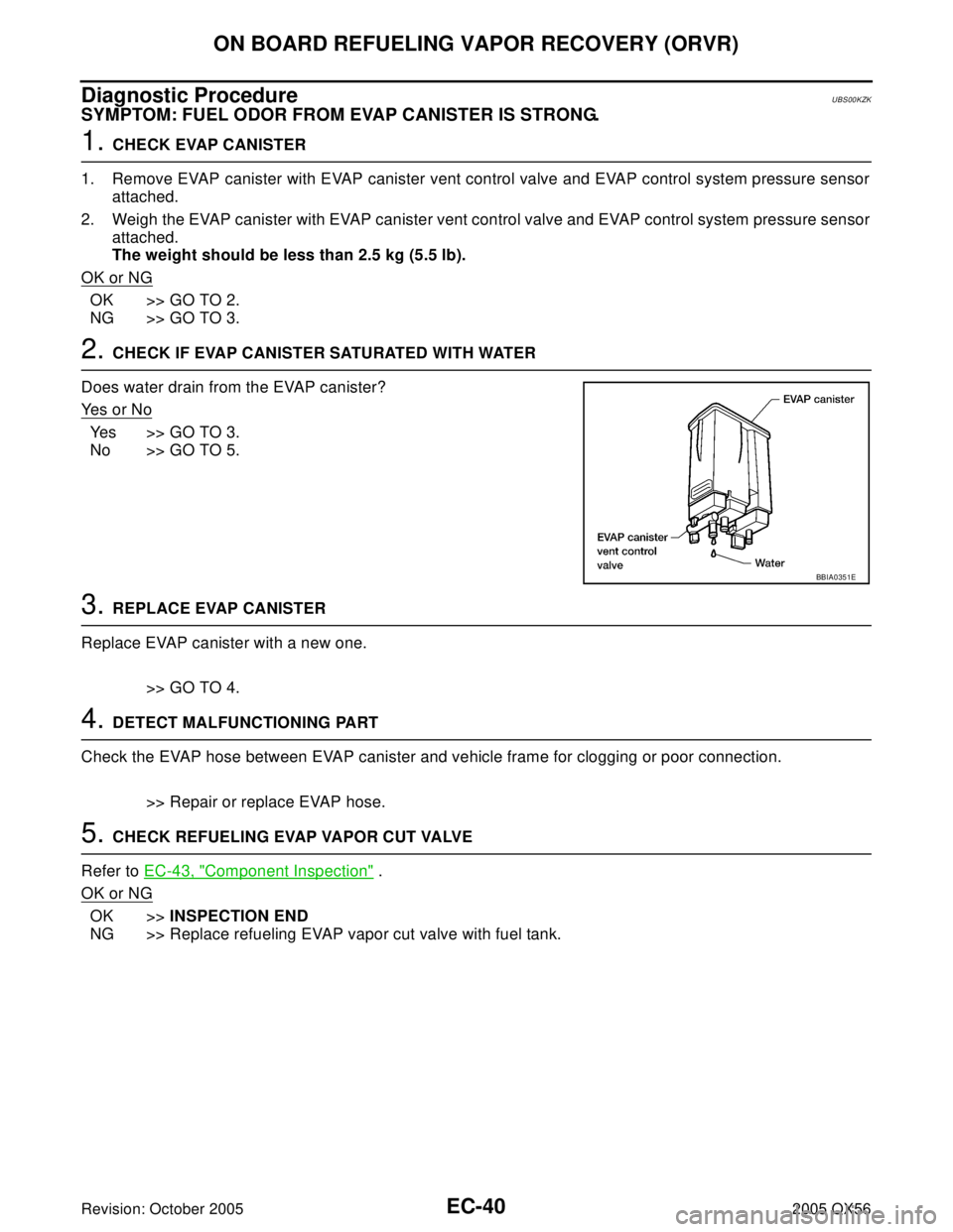
2. CHECK IF EVAP CANISTER SATURATED WITH WATER
Does water drain from the EVAP canister?
Ye s o r N o
Yes >> GO TO 3.
No >> GO TO 5.
3. REPLACE EVAP CANISTER
Replace EVAP canister with a new one.
>> GO TO 4.
4. DETECT MALFUNCTIONING PART
Check the EVAP hose between EVAP canister and vehicle frame for clogging or poor connection.
>> Repair or replace EVAP hose.
5. CHECK REFUELING EVAP VAPOR CUT VALVE
Refer to EC-43, "
Component Inspection" .
OK or NG
OK >>INSPECTION END
NG >> Replace refueling EVAP vapor cut valve with fuel tank.
BBIA0351E
Page 1232 of 3419
ON BOARD REFUELING VAPOR RECOVERY (ORVR)
EC-41
C
D
E
F
G
H
I
J
K
L
MA
EC
Revision: October 20052005 QX56
SYMPTOM: CANNOT REFUEL/FUEL ODOR FROM THE FUEL FILLER OPENING IS STRONG
WHILE REFUELING.
1. CHECK EVAP CANISTER
1. Remove EVAP canister with EVAP canister vent control valve and EVAP control system pressure sensor
attached.
2. Weigh the EVAP canister with EVAP canister vent control valve and EVAP control system pressure sensor
attached.
The weight should be less than 2.5 kg (5.5 lb).
OK or NG
OK >> GO TO 2.
NG >> GO TO 3.
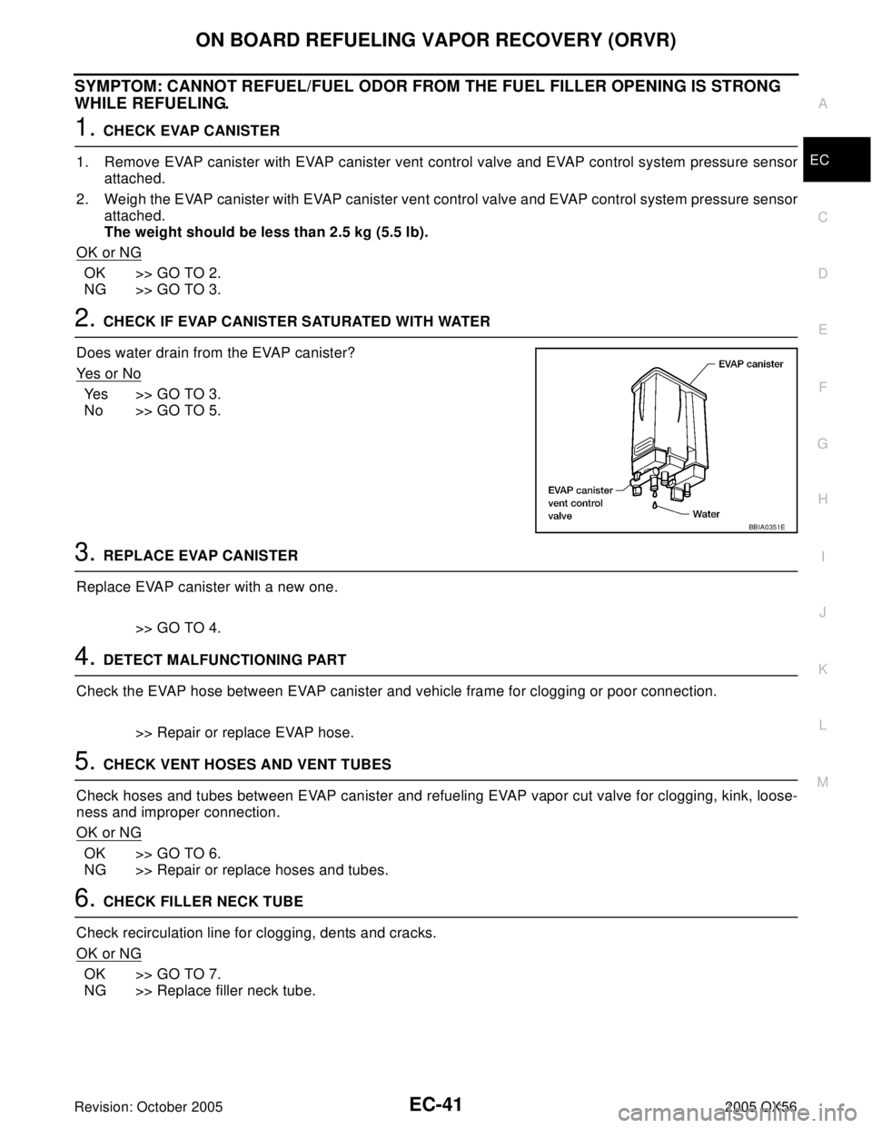
2. CHECK IF EVAP CANISTER SATURATED WITH WATER
Does water drain from the EVAP canister?
Ye s o r N o
Yes >> GO TO 3.
No >> GO TO 5.
3. REPLACE EVAP CANISTER
Replace EVAP canister with a new one.
>> GO TO 4.
4. DETECT MALFUNCTIONING PART
Check the EVAP hose between EVAP canister and vehicle frame for clogging or poor connection.
>> Repair or replace EVAP hose.
5. CHECK VENT HOSES AND VENT TUBES
Check hoses and tubes between EVAP canister and refueling EVAP vapor cut valve for clogging, kink, loose-
ness and improper connection.
OK or NG
OK >> GO TO 6.
NG >> Repair or replace hoses and tubes.
6. CHECK FILLER NECK TUBE
Check recirculation line for clogging, dents and cracks.
OK or NG
OK >> GO TO 7.
NG >> Replace filler neck tube.
BBIA0351E
Page 1234 of 3419
ON BOARD REFUELING VAPOR RECOVERY (ORVR)
EC-43
C
D
E
F
G
H
I
J
K
L
MA
EC
Revision: October 20052005 QX56
Component InspectionUBS00KZL
REFUELING EVAP VAPOR CUT VALVE
With CONSULT-II
1. Remove fuel tank. Refer to FL-9, "FUEL TANK" .
2. Drain fuel from the tank as follows:
a. Remove fuel feed hose located on the fuel gauge retainer.
b. Connect a spare fuel hose, one side to fuel gauge retainer where the hose was removed and the other
side to a fuel container.
c. Drain fuel using “FUEL PUMP RELAY” in “ACTIVE TEST” mode with CONSULT-II.
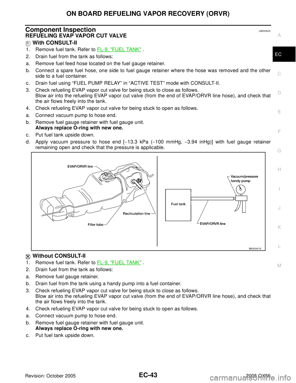
3. Check refueling EVAP vapor cut valve for being stuck to close as follows.
Blow air into the refueling EVAP vapor cut valve (from the end of EVAP/ORVR line hose), and check that
the air flows freely into the tank.
4. Check refueling EVAP vapor cut valve for being stuck to open as follows.
a. Connect vacuum pump to hose end.
b. Remove fuel gauge retainer with fuel gauge unit.
Always replace O-ring with new one.
c. Put fuel tank upside down.
d. Apply vacuum pressure to hose end [−13.3 kPa (−100 mmHg, −3.94 inHg)] with fuel gauge retainer
remaining open and check that the pressure is applicable.
Without CONSULT-II
1. Remove fuel tank. Refer to FL-9, "FUEL TANK" .
2. Drain fuel from the tank as follows:
a. Remove fuel gauge retainer.
b. Drain fuel from the tank using a handy pump into a fuel container.
3. Check refueling EVAP vapor cut valve for being stuck to close as follows.
Blow air into the refueling EVAP vapor cut valve (from the end of EVAP/ORVR line hose), and check that
the air flows freely into the tank.
4. Check refueling EVAP vapor cut valve for being stuck to open as follows.
a. Connect vacuum pump to hose end.
b. Remove fuel gauge retainer with fuel gauge unit.
Always replace O-ring with new one.
c. Put fuel tank upside down.
BBIA0401E
Page 1235 of 3419
EC-44Revision: October 2005
ON BOARD REFUELING VAPOR RECOVERY (ORVR)
2005 QX56
d. Apply vacuum pressure to hose end [−13.3 kPa (−100 mmHg, −3.94 inHg)] with fuel gauge retainer
remaining open and check that the pressure is applicable.
BBIA0401E
Page 1270 of 3419
BASIC SERVICE PROCEDURE
EC-79
C
D
E
F
G
H
I
J
K
L
MA
EC
Revision: October 20052005 QX56
Idle Mixture Ratio AdjustmentUBS00KZW
PREPARATION
1. Make sure that the following parts are in good order.
�Battery
�Ignition system
�Engine oil and coolant levels
�Fuses
�ECM harness connector
�Vacuum hoses
�Air intake system
(Oil filler cap, oil level gauge, etc.)
�Fuel pressure
�Engine compression
�Throttle valve
�Evaporative emission system
2. On air conditioner equipped models, checks should be carried out while the air conditioner is OFF.
3. Checks should be carried out while selector lever is in P or N position.
4. When measuring CO percentage, insert probe more than 40 cm (15.7 in) into tail pipe.
5. Turn off headlamp, heater blower, rear window defogger.
6. Keep front wheels pointed straight ahead.
Page 1280 of 3419
BASIC SERVICE PROCEDURE
EC-89
C
D
E
F
G
H
I
J
K
L
MA
EC
Revision: October 20052005 QX56
29. CHECK AIR FUEL RATIO (A/F) SENSOR 1 FUNCTION
With CONSULT-II
1. Turn ignition switch OFF and wait at a least 10 seconds.
2. Start engine and warm it up to normal operating temperature.
3. Drive the vehicle at a speed of 80 km/h (50 MPH) for a few minutes in D position.
NOTE:
Keep the accelerator pedal as steady as possible during the cruising.
4. Release the accelerator pedal fully until the vehicle speed decreases to 50 km/h (30 MPH).
NOTE:
Never apply brake during releasing the accelerator pedal.
5. Repeat steps 3 to 4 for 5 times.
6. Stop the vehicle and connect CONSULT-II to the vehicle.
7. Make sure that no (1st trip) DTC is displayed in “SELF-DIAG RESULTS” mode.
OK or NG
OK >> GO TO 4.
NG >> GO TO 31.
30. CHECK AIR FUEL RATIO (A/F) SENSOR 1 FUNCTION
With GST
1. Turn ignition switch OFF and wait at a least 10 seconds.
2. Start engine and warm it up to normal operating temperature.
3. Drive the vehicle at a speed of 80 km/h (50 MPH) for a few minutes in D position.
NOTE:
Keep the accelerator pedal as steady as possible during the cruising.
4. Release the accelerator pedal fully until the vehicle speed decreases to 50 km/h (30 MPH).
NOTE:
Never apply brake during releasing the accelerator pedal.
5. Repeat steps 3 to 4 for 5 times.
6. Stop the vehicle and connect GST to the vehicle.
7. Make sure that no (1st trip) DTC is displayed.
OK or NG
OK >> GO TO 4.
NG >> GO TO 31.
31. DETECT MALFUNCTIONING PART
Check the following.
�Check fuel pressure regulator, and repair or replace if necessary. Refer to EC-93, "Fuel Pressure Check" .
�Check mass air flow sensor and its circuit, and repair or replace if necessary. Refer to EC-174, "DTC
P0101 MAF SENSOR" and EC-183, "DTC P0102, P0103 MAF SENSOR" .
�Check injector and its circuit, and repair or replace if necessary. Refer to EC-631, "INJECTOR CIRCUIT" .
�Check engine coolant temperature sensor and its circuit, and repair or replace if necessary. Refer to EC-
195, "DTC P0117, P0118 ECT SENSOR" and EC-208, "DTC P0125 ECT SENSOR" .
OK or NG
OK >> GO TO 33.
NG >> 1. Repair or replace.
2. GO TO 32.
Page 1284 of 3419
BASIC SERVICE PROCEDURE
EC-93
C
D
E
F
G
H
I
J
K
L
MA
EC
Revision: October 20052005 QX5613. If idle speed and ignition timing are not within the specification, Idle Air Volume Learning will not be carried
out successfully. In this case, find the cause of the incident by referring to the DIAGNOSTIC PROCE-
DURE below.
DIAGNOSTIC PROCEDURE
If idle air volume learning cannot be performed successfully, proceed as follows:
1.Check that throttle valve is fully closed.
2.Check PCV valve operation.
3.Check that downstream of throttle valve is free from air leakage.
4.When the above three items check out OK, engine component parts and their installation condi-
tion are questionable. Check and eliminate the cause of the incident.
It is useful to perform EC-146, "
TROUBLE DIAGNOSIS - SPECIFICATION VALUE" .
5.If any of the following conditions occur after the engine has started, eliminate the cause of the
incident and perform Idle Air Volume Learning all over again:
�Engine stalls.
�Erroneous idle.
Fuel Pressure CheckUBS00L01
FUEL PRESSURE RELEASE
With CONSULT-II
1. Turn ignition switch ON.
2. Perform “FUEL PRESSURE RELEASE” in “WORK SUPPORT”
mode with CONSULT-II.
3. Start engine.
4. After engine stalls, crank it two or three times to release all fuel
pressure.
5. Turn ignition switch OFF.
Without CONSULT-II
1. Remove fuel pump fuse located in IPDM E/R.
2. Start engine.
3. After engine stalls, crank it two or three times to release all fuel
pressure.
4. Turn ignition switch OFF.
5. Reinstall fuel pump fuse after servicing fuel system.
ITEM SPECIFICATION
Idle speed 650 ± 50 rpm (in P or N position)
Ignition timing 15 ± 5° BTDC (in P or N position)
SEF 2 14 Y
BBIA0380E