Page 2807 of 3419
 TROUBLESHOOTING
Revision: October 20052005 QX56
NOISE, VIBRATION, AND HARSHNESS (NVH) TROUBLESHOOTINGPFP:00003
NVH Troubleshooting ChartEDS001XM
Use chart b")
RAX-4
NOISE, VIBRATION, AND HARSHNESS (NVH) TROUBLESHOOTING
Revision: October 20052005 QX56
NOISE, VIBRATION, AND HARSHNESS (NVH) TROUBLESHOOTINGPFP:00003
NVH Troubleshooting ChartEDS001XM
Use chart below to help you find the cause of the symptom. If necessary, repair or replace these parts.
×: ApplicableReference page
—
RAX-8—
RAX-5—
RFD-10, "REMOVAL
"
FAX -4, "
NVH Troubleshooting Chart
" (FAX), FSU-4, "
NVH Troubleshooting Chart
" (FSU)
RSU-5, "
NVH Troubleshooting Chart
"
WT-4, "
NVH Troubleshooting Chart
"
WT-4, "
NVH Troubleshooting Chart
"
PR-3, "
NVH Troubleshooting Chart
"
BR-5, "
NVH Troubleshooting Chart
"
PS-5, "
NVH Troubleshooting Chart
"
Possible cause and SUSPECTED PARTS
Excessive joint angle
Joint sliding resistance
Imbalance
Improper installation, looseness
Parts interference
DIFFERENTIAL
FRONT AXLE AND FRONT SUSPENSION
REAR SUSPENSION
TIRES
ROAD WHEEL
PROPELLER SHAFT
BRAKES
STEERING
SymptomNoise×× ×× ×× ×××××
Shake× × ×× × ×××××
Vibration×× ×× × × × ×
Shimmy×× ×××××
Shudder× × ×× ××
Poor quality ride or handling×× ×× ×× ×
Page 2848 of 3419

RFD-1
REAR FINAL DRIVE
D DRIVELINE/AXLE
CONTENTS
C
E
F
G
H
I
J
K
L
M
SECTION RFD
A
B
RFD
Revision: October 20052005 QX56 PREPARATION ........................................................... 2
Special Service Tools ............................................... 2
Commercial Service Tools ........................................ 4
NOISE, VIBRATION, AND HARSHNESS (NVH)
TROUBLESHOOTING ................................................ 5
NVH Troubleshooting Chart ..................................... 5
FRONT OIL SEAL ...................................................... 6
Removal and Installation .......................................... 6
REMOVAL ............................................................. 6
INSTALLATION ..................................................... 7
SIDE OIL SEAL .......................................................... 8
Removal and Installation .......................................... 8
REMOVAL ............................................................. 8
INSTALLATION ..................................................... 8
REAR FINAL DRIVE ASSEMBLY ............................ 10
Removal and Installation ........................................ 10
REMOVAL ........................................................... 10
INSTALLATION ....................................................11
Components ........................................................... 12
Pre-Inspection ........................................................ 13
TOTAL PRELOAD ............................................... 13
DRIVE GEAR TO DRIVE PINION BACKLASH ... 13
DRIVE GEAR RUNOUT ...................................... 13
COMPANION FLANGE RUNOUT ...................... 14
TOOTH CONTACT .............................................. 14
Disassembly and Assembly ................................... 14
REMOVAL OF DIFFERENTIAL CASE ASSEM-BLY ...................................................................... 14
REMOVAL OF DRIVE PINION ASSEMBLY ........ 15
DISASSEMBLY OF DIFFERENTIAL CASE
ASSEMBLY ......................................................... 17
INSPECTION ...................................................... 18
ADJUSTMENT OF DIFFERENTIAL CASE ......... 18
SIDE BEARING PRELOAD ................................. 19
TOOTH CONTACT .............................................. 20
ASSEMBLY OF DIFFERENTIAL CASE ASSEM-
BLY ...................................................................... 21
INSTALLATION OF DRIVE PINION ASSEMBLY ... 22
INSTALLATION OF DIFFERENTIAL CASE
ASSEMBLY ......................................................... 24
SERVICE DATA AND SPECIFICATIONS (SDS) ...... 27
General Specifications ............................................ 27
Drive Gear Runout .................................................. 27
Side Gear Adjustment ............................................ 27
AVAILABLE SIDE GEAR THRUST WASHERS ... 27
Drive Pinion Height Adjustment .............................. 27
AVAILABLE PINION HEIGHT ADJUSTING
WASHERS .......................................................... 27
Drive Pinion Preload Adjustment ............................ 27
Side Bearing Preload Adjustment ........................... 28
SIDE BEARING ADJUSTING WASHERS .......... 28
Total Preload Adjustment ........................................ 28
Page 2849 of 3419

RFD-2
PREPARATION
Revision: October 20052005 QX56
PREPARATIONPFP:00002
Special Service ToolsEDS003Q6
The actual shapes of the tools may differ from those of the special service tools illustrated here.
Tool name
Tool numberDescription
Drift
ST15310000
�Installing front oil seal
�Installing drive pinion rear bearing outer
race.
a: 96 mm (3.77 in) dia.
b: 84 mm (3.30 in) dia.
Drift
ST35271000Installing side oil seal
a: 72 mm (2.83 in) dia.
b: 63 mm (2.48 in) dia.
Protector
KV38107900Installing side flange
Attachment
KV38100800 Fixing unit assembly
a: 541 mm (21.30 in) dia.
b: 200 mm (7.87 in) dia.
Differential side bearing puller set
ST3306S001
1.ST33051001
2.ST33061000Removing side bearing inner race
a: 28.5 mm (1.122 in) dia.
b: 38 mm (1.50 in) dia.
Drift
ST30621000Installing drive pinion front bearing outer race
a: 79 mm (3.11 in) dia.
b: 59 mm (2.32 in) dia.
Drift
KV38100200Installing side bearing inner race
a: 65 mm (2.55 in) dia.
b: 49 mm (1.92 in) dia.
ZZA0811D
ZZA1143D
S-NT129
SDIA0267E
NT072
ZZA0810D
ZZA1143D
Page 2850 of 3419
PREPARATION
RFD-3
C
E
F
G
H
I
J
K
L
MA
B
RFD
Revision: October 20052005 QX56
Drive pinion flange wrench
KV40104000Removing and installing drive pinion nut
a: 85 mm (3.35 in) dia.
b: 65 mm (2.56 in) dia.
Slide hammer
ST36230000Removing side flange
Axle stand
KV40104100Removing side flange
Slide hammer
HT72400000Removing differential case assembly
Drift
ST35325000Installing drive pinion rear bearing outer race
(use with ST30621000)
Preload gauge
ST3127S000
1. Torque wrench
GG91030000
2. Socket adapter (1/2 in)
HT62940000
3. Socket adapter (3/8 in)
HT62900000Measuring pinion bearing preload and total
preload
Side bearing outer race puller
ST33290001Removing front oil seal Tool name
Tool numberDescription
NT659
ZZA0803D
ZZA0804D
S-NT125
S-NT090
NT124
ZZA0601D
Page 2860 of 3419

REAR FINAL DRIVE ASSEMBLY
RFD-13
C
E
F
G
H
I
J
K
L
MA
B
RFD
Revision: October 20052005 QX56CAUTION:
Final drive pinion nut torque will be determined when adjusting the total preload. Refer to RFD-13,
"TOTAL PRELOAD" .
Pre-InspectionEDS003QD
Before disassembling the rear final drive, perform the following inspections.
TOTAL PRELOAD
1. Turn the drive pinion in both directions several times to set the
bearing rollers.
2. Check the total preload using Tool.
DRIVE GEAR TO DRIVE PINION BACKLASH
Check the drive gear to drive pinion backlash using a dial gauge at
several points as shown.
DRIVE GEAR RUNOUT
Check the runout of the drive gear using a dial gauge as shown.
1. Drive pinion nut 2. Companion flange 3. Front oil seal
4. Pinion front bearing 5. Pinion bearing adjusting spacer (col-
lapsible spacer)6. Pinion rear bearing
7. Pinion height adjusting washer 8. Drive pinion 9. Gear carrier
10. Drive gear 11. Pinion mate shaft 12. Lock pin
13. Pinion mate gear 14. Pinion mate thrust washer 15. Side gear
16. Side gear thrust washer 17. Differential case 18. Side bearing
19. Side bearing adjusting washer 20. Bearing cap 21. Rear cover
22. Filler plug 23. Drain plug 24. Side oil seal
Tool number : ST3127S000
Total preload : 2.05 - 4.11 N·m (0.21 - 0.42 kg-m,
19 - 36 in-lb)
SPD8 84
Drive gear to drive pinion backlash : 0.13 - 0.18 mm
(0.0051 - 0.0070 in)
SPD5 13
Runout limit : 0.05 mm (0.0020 in) or less
SPD8 86
Page 2861 of 3419

RFD-14
REAR FINAL DRIVE ASSEMBLY
Revision: October 20052005 QX56
COMPANION FLANGE RUNOUT
Mount the dial gauge indicator so the dial gauge needle is positioned
on the propeller shaft mounting surface. Rotate the companion
flange and measure the runout as shown.
�If runout is not within specification, remove the companion
flange, rotate 90° in relation to the drive pinion, and install the
companion flange using a new drive pinion nut. Tighten the drive
pinion nut to the minimum specified torque. Final drive pinion nut
torque will be determined when adjusting the total preload. Refer
to RFD-13, "
TOTAL PRELOAD" .
CAUTION:
The drive pinion nut is not reusable. Use a new drive pinion nut for installation.
�If runout is not within specification after rotating the companion flange 90° on the drive pinion, replace the
companion flange. Recheck the companion flange runout.
�If the new companion flange runout is not within specification, inspect the drive pinion bearing and the
drive pinion. Repair as necessary.
CAUTION:
Clean all of the rust and dirt off of the companion flange surface before measuring the companion
flange runout.
TOOTH CONTACT
Check the tooth contact. Refer to RFD-14, "TOOTH CONTACT" .
Disassembly and AssemblyEDS003QE
REMOVAL OF DIFFERENTIAL CASE ASSEMBLY
1. Use two 45 mm (1.77 in) spacers to mount the gear carrier on
Tool.
2. For installation, paint match marks on one side of the bearing
caps as shown.
NOTE:
Bearing caps are line-bored for initial assembly. Replace the
bearing caps in their original positions.Companion flange runout : 0.08 mm (0.003 in) or less
Tool number : KV40104000
Drive pinion nut : 167 - 372 N·m (17 - 38 kg-m,
124 - 274 ft-lb)
WDIA0062E
Tool number : KV38100800
SPD8 88
SPD8 89
Page 2862 of 3419
REAR FINAL DRIVE ASSEMBLY
RFD-15
C
E
F
G
H
I
J
K
L
MA
B
RFD
Revision: October 20052005 QX56
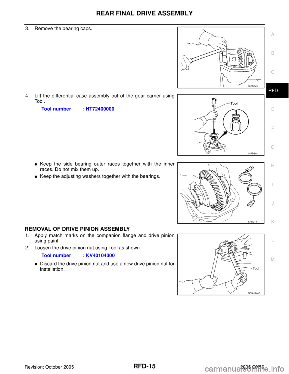
3. Remove the bearing caps.
4. Lift the differential case assembly out of the gear carrier using
Tool.
�Keep the side bearing outer races together with the inner
races. Do not mix them up.
�Keep the adjusting washers together with the bearings.
REMOVAL OF DRIVE PINION ASSEMBLY
1. Apply match marks on the companion flange and drive pinion
using paint.
2. Loosen the drive pinion nut using Tool as shown.
�Discard the drive pinion nut and use a new drive pinion nut for
installation.
S-PD3 43
Tool number : HT72400000
S-PD3 44
SPD9 19
Tool number : KV40104000
SDIA11 44 E
Page 2864 of 3419
REAR FINAL DRIVE ASSEMBLY
RFD-17
C
E
F
G
H
I
J
K
L
MA
B
RFD
Revision: October 20052005 QX56
DISASSEMBLY OF DIFFERENTIAL CASE ASSEMBLY
1. Remove the side bearing inner races using Tools.
CAUTION:
To prevent damage to the bearing, engage the puller jaws in
the groove.
�Do not to mix the left and right side parts, clearly label the
parts during disassembly.
2. Loosen the drive gear bolts in a criss-cross pattern and remove
the bolts.
3. Tap the drive gear off the differential case using a soft hammer.
�Tap evenly all around the drive gear to keep the drive gear
from binding.Tool number A: ST3306S001
B: ST33061000
SPD9 20
SPD0 22
SPD0 24
 dia.
b: 65 mm (2.56 in) di")