Page 2047 of 3419
FFD-16
FRONT FINAL DRIVE ASSEMBLY
Revision: October 20052005 QX56
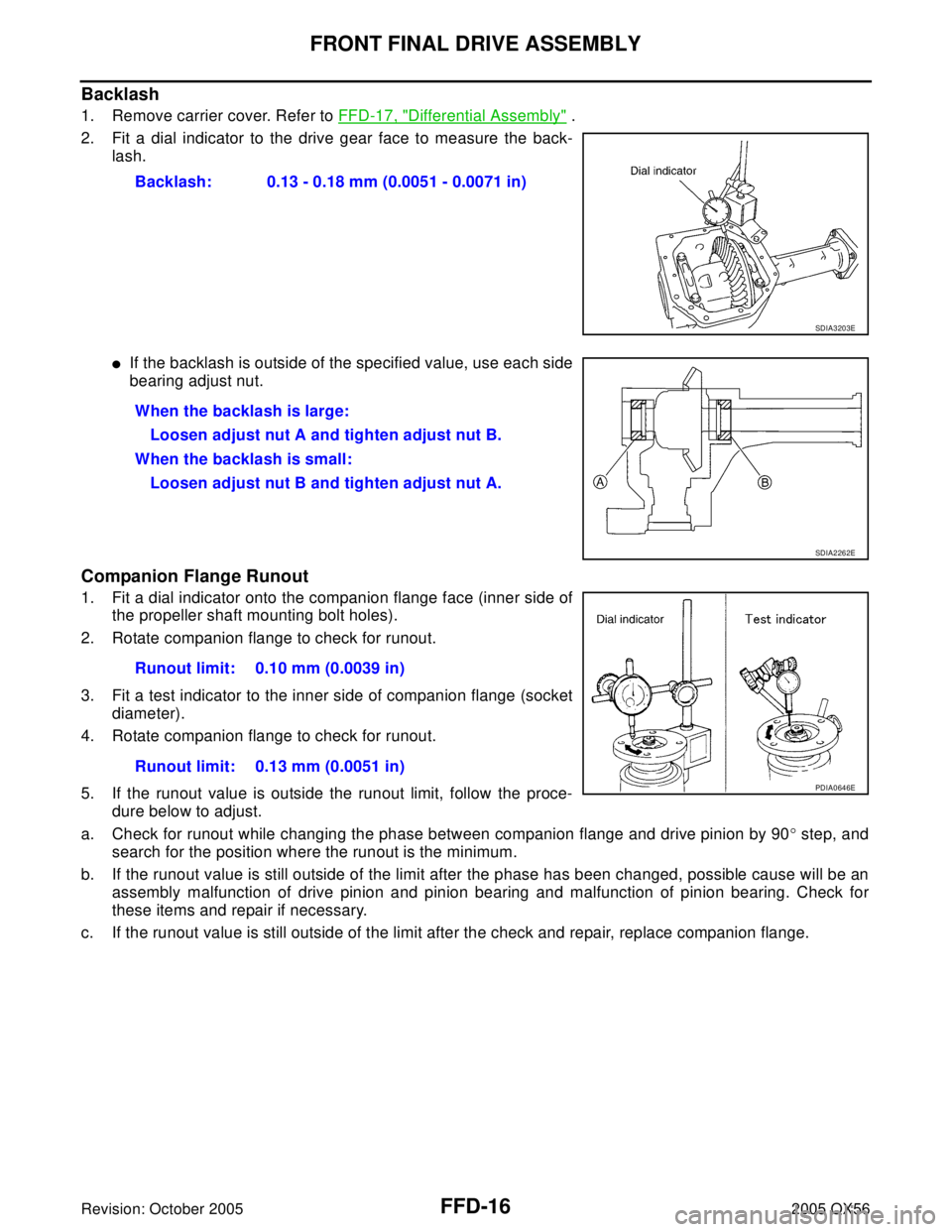
Backlash
1. Remove carrier cover. Refer to FFD-17, "Differential Assembly" .
2. Fit a dial indicator to the drive gear face to measure the back-
lash.
�If the backlash is outside of the specified value, use each side
bearing adjust nut.
Companion Flange Runout
1. Fit a dial indicator onto the companion flange face (inner side of
the propeller shaft mounting bolt holes).
2. Rotate companion flange to check for runout.
3. Fit a test indicator to the inner side of companion flange (socket
diameter).
4. Rotate companion flange to check for runout.
5. If the runout value is outside the runout limit, follow the proce-
dure below to adjust.
a. Check for runout while changing the phase between companion flange and drive pinion by 90° step, and
search for the position where the runout is the minimum.
b. If the runout value is still outside of the limit after the phase has been changed, possible cause will be an
assembly malfunction of drive pinion and pinion bearing and malfunction of pinion bearing. Check for
these items and repair if necessary.
c. If the runout value is still outside of the limit after the check and repair, replace companion flange.Backlash: 0.13 - 0.18 mm (0.0051 - 0.0071 in)
SDIA3203E
When the backlash is large:
Loosen adjust nut A and tighten adjust nut B.
When the backlash is small:
Loosen adjust nut B and tighten adjust nut A.
SDIA2262E
Runout limit: 0.10 mm (0.0039 in)
Runout limit: 0.13 mm (0.0051 in)
PDIA0646E
Page 2048 of 3419
FRONT FINAL DRIVE ASSEMBLY
FFD-17
C
E
F
G
H
I
J
K
L
MA
B
FFD
Revision: October 20052005 QX56
DISASSEMBLY
Differential Assembly
1. Drain gear oil, if necessary.
2. Remove differential side shaft with a soft hammer.
3. Remove differential side flange with a soft hammer.
4. Remove extension tube and O-ring.
5. Place a small hole in seal case, using a suitable punch or drill.
SDIA2223E
SDIA2224E
SDIA3205E
LDIA0129E
Page 2050 of 3419
FRONT FINAL DRIVE ASSEMBLY
FFD-19
C
E
F
G
H
I
J
K
L
MA
B
FFD
Revision: October 20052005 QX56
11. Keep the side bearing outer races together with inner race. Do
not mix them up.
12. Remove side bearing inner race.
To prevent damage to bearing, engage puller jaws in groove.
CAUTION:
�To prevent damage to the side bearing and drive gear,
place copper plates between these parts and vise.
�It is not necessary to remove side bearing except it is
replaced.
�Be careful not to confuse left-hand and right-hand parts.
Keep bearing and bearing race for each side together.
13. Loosen drive gear mounting bolts in a crisscross fashion.
14. Tap drive gear off the differential case with a soft hammer.
�Tap evenly all around to keep the drive gear from bending.
15. Drive out pinion mate shaft lock pin with suitable punch from
drive gear side.
SPD5 27
Tool number A: ST33081000
B: ST30021000
SDIA2237E
SPD0 22
SDIA2238E
SPD0 25
Page 2051 of 3419
FFD-20
FRONT FINAL DRIVE ASSEMBLY
Revision: October 20052005 QX56
16. Remove the pinion mate shaft.
17. Turn the pinion mate gear, then remove the pinion mate gear,
pinion mate thrust washer, side gear and side gear thrust
washer from the differential case.
Drive Pinion Assembly
1. Remove differential assembly. Refer to FFD-17, "Differential Assembly" .
2. Put matching marks on companion flange and drive pinion with
paint.
3. Loosen drive pinion nut using Tool.
4. Remove companion flange using a suitable puller.
SDIA0031J
SDIA0032J
Tool number : KV38108300 (6958)
SDIA2232E
SDIA2233E
Page 2053 of 3419
FFD-22
FRONT FINAL DRIVE ASSEMBLY
Revision: October 20052005 QX56
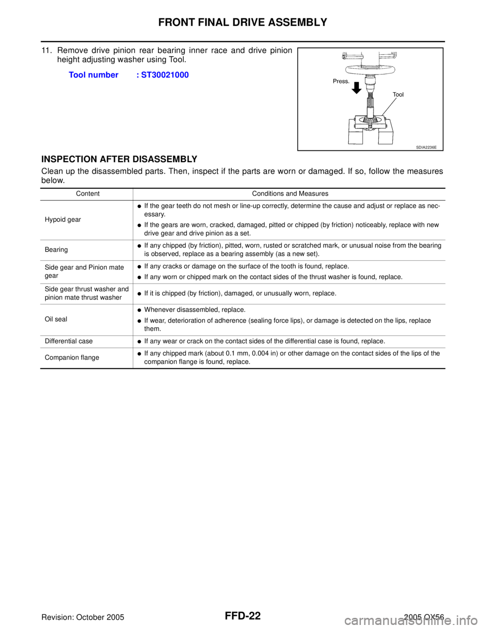
11. Remove drive pinion rear bearing inner race and drive pinion
height adjusting washer using Tool.
INSPECTION AFTER DISASSEMBLY
Clean up the disassembled parts. Then, inspect if the parts are worn or damaged. If so, follow the measures
below.Tool number : ST30021000
SDIA2236E
Content Conditions and Measures
Hypoid gear
�If the gear teeth do not mesh or line-up correctly, determine the cause and adjust or replace as nec-
essary.
�If the gears are worn, cracked, damaged, pitted or chipped (by friction) noticeably, replace with new
drive gear and drive pinion as a set.
Bearing
�If any chipped (by friction), pitted, worn, rusted or scratched mark, or unusual noise from the bearing
is observed, replace as a bearing assembly (as a new set).
Side gear and Pinion mate
gear
�If any cracks or damage on the surface of the tooth is found, replace.
�If any worn or chipped mark on the contact sides of the thrust washer is found, replace.
Side gear thrust washer and
pinion mate thrust washer
�If it is chipped (by friction), damaged, or unusually worn, replace.
Oil seal
�Whenever disassembled, replace.
�If wear, deterioration of adherence (sealing force lips), or damage is detected on the lips, replace
them.
Differential case
�If any wear or crack on the contact sides of the differential case is found, replace.
Companion flange
�If any chipped mark (about 0.1 mm, 0.004 in) or other damage on the contact sides of the lips of the
companion flange is found, replace.
Page 2054 of 3419
FRONT FINAL DRIVE ASSEMBLY
FFD-23
C
E
F
G
H
I
J
K
L
MA
B
FFD
Revision: October 20052005 QX56
ADJUSTMENT AND SELECTION OF ADJUSTING WASHERS
Differential Side Gear Clearance
�Assemble the differential parts if they are disassembled. Refer to FFD-17, "Differential Assembly" .
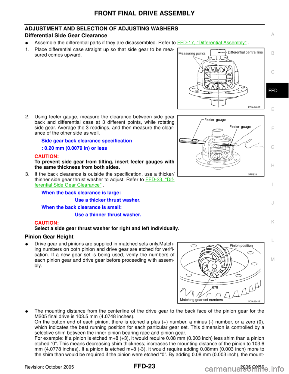
1. Place differential case straight up so that side gear to be mea-
sured comes upward.
2. Using feeler gauge, measure the clearance between side gear
back and differential case at 3 different points, while rotating
side gear. Average the 3 readings, and then measure the clear-
ance of the other side as well.
CAUTION:
To prevent side gear from tilting, insert feeler gauges with
the same thickness from both sides.
3. If the back clearance is outside the specification, use a thicker/
thinner side gear thrust washer to adjust. Refer to FFD-23, "
Dif-
ferential Side Gear Clearance" .
CAUTION:
Select a side gear thrust washer for right and left individually.
Pinion Gear Height
�Drive gear and pinions are supplied in matched sets only.Match-
ing numbers on both pinion and drive gear are etched for verifi-
cation. If a new gear set is being used, verify the numbers of
each pinion gear and drive gear before proceeding with assem-
bly.
�The mounting distance from the centerline of the drive gear to the back face of the pinion gear for the
M205 final drive is 103.5 mm (4.0748 inches).
On the button end of each pinion, there is etched a plus (+) number, a minus (-) number, or a zero (0),
which indicates the best running position for each particular gear set. This dimension is controlled by a
selective shim between the inner pinion bearing race and pinion gear.
For example: If a pinion is etched m+8 (+3), it would require 0.08 mm (0.003 inch) less shim than a pinion
etched “0”. This means decreasing shim thickness; increases the mounting distance of the pinion to 103.6
mm (4.0778 inches). If a pinion is etched m+8 (-3), it would require adding 0.08mm (0.003 inch) more to
the shim than would be required if the pinion were etched “0”. By adding 0.08 mm (0.003 inch), the mount-
PDIA0460E
Side gear back clearance specification
: 0.20 mm (0.0079 in) or less
When the back clearance is large:
Use a thicker thrust washer.
When the back clearance is small:
Use a thinner thrust washer.
SPD8 28
SDIA2241E
Page 2057 of 3419
FFD-26
FRONT FINAL DRIVE ASSEMBLY
Revision: October 20052005 QX56
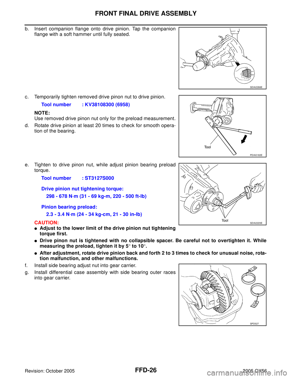
b. Insert companion flange onto drive pinion. Tap the companion
flange with a soft hammer until fully seated.
c. Temporarily tighten removed drive pinon nut to drive pinion.
NOTE:
Use removed drive pinon nut only for the preload measurement.
d. Rotate drive pinion at least 20 times to check for smooth opera-
tion of the bearing.
e. Tighten to drive pinon nut, while adjust pinion bearing preload
torque.
CAUTION:
�Adjust to the lower limit of the drive pinion nut tightening
torque first.
�Drive pinon nut is tightened with no collapsible spacer. Be careful not to overtighten it. While
measuring the preload, tighten it by 5° to 10°.
�After adjustment, rotate drive pinion back and forth 2 to 3 times to check for unusual noise, rota-
tion malfunction, and other malfunctions.
f. Install side bearing adjust nut into gear carrier.
g. Install differential case assembly with side bearing outer races
into gear carrier.
SDIA2266E
Tool number : KV38108300 (6958)
PDIA0182E
Tool number : ST3127S000
Drive pinion nut tightening torque:
298 - 678 N·m (31 - 69 kg-m, 220 - 500 ft-lb)
Pinion bearing preload:
2.3 - 3.4 N·m (24 - 34 kg-cm, 21 - 30 in-lb)
SDIA2220E
SPD5 27
Page 2058 of 3419
FRONT FINAL DRIVE ASSEMBLY
FFD-27
C
E
F
G
H
I
J
K
L
MA
B
FFD
Revision: October 20052005 QX56
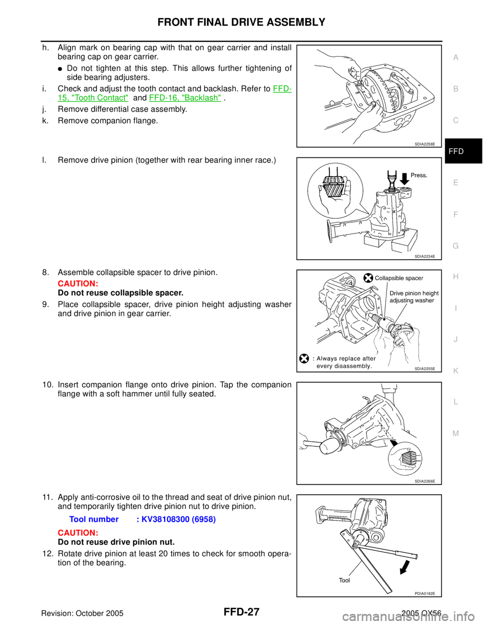
h. Align mark on bearing cap with that on gear carrier and install
bearing cap on gear carrier.
�Do not tighten at this step. This allows further tightening of
side bearing adjusters.
i. Check and adjust the tooth contact and backlash. Refer to FFD-
15, "Tooth Contact" and FFD-16, "Backlash" .
j. Remove differential case assembly.
k. Remove companion flange.
l. Remove drive pinion (together with rear bearing inner race.)
8. Assemble collapsible spacer to drive pinion.
CAUTION:
Do not reuse collapsible spacer.
9. Place collapsible spacer, drive pinion height adjusting washer
and drive pinion in gear carrier.
10. Insert companion flange onto drive pinion. Tap the companion
flange with a soft hammer until fully seated.
11. Apply anti-corrosive oil to the thread and seat of drive pinion nut,
and temporarily tighten drive pinion nut to drive pinion.
CAUTION:
Do not reuse drive pinion nut.
12. Rotate drive pinion at least 20 times to check for smooth opera-
tion of the bearing.
SDIA2258E
SDIA2234E
SDIA2255E
SDIA2266E
Tool number : KV38108300 (6958)
PDIA0182E