FRONT WIPER AND WASHER SYSTEM
WW-15
C
D
E
F
G
H
I
J
L
MA
B
WW
Revision: October 20052005 QX56
Terminals and Reference Values for IPDM E/R EKS00BDY
Work FlowEKS00BDZ
1. Confirm the trouble symptom or customer complaint.
2. Understand the system description, refer to WW-4, "
System Description" .
3. Perform preliminary inspection, refer to WW-15, "
Preliminary Inspection" .
4. Check symptom and repair or replace the cause of malfunction.
5. Does wiper function operate normally? If it operates normally, GO TO 6. If not, GO TO 4.
6. Inspection End.
Preliminary InspectionEKS00BE0
INSPECTION FOR POWER SUPPLY AND GROUND CIRCUIT
Inspection procedure
1. CHECK FUSE
Check if wiper or washer fuse is blown.
35 O/B Combination switch output 2
ON
�Light switch and wiper switch OFF
�Wiper dial position 4
36 R/W Combination switch output 1
38 W/L Ignition switch (ON) ON — Battery
39 L CAN-H ON — —
40 P CAN-L ON — —
67 B Ground — — 0
70 W/B Battery power OFF — Battery Te r m i -
nal No.Wire
colorSignal nameMeasuring condition
Reference Value (V)
(Approx.) Ignition
switchOperation or condition
SKIA5292E
Te r m i n a l
No.Wire
colorSignal nameMeasuring condition
Reference value (V)
(Approx.) Ignition
switchOperation or condition
32 L Low speed signal ON Wiper switchOFF 0
LO Battery
35 L/B High speed signal ON Wiper switchOFF 0
HI Battery
38 B Ground — — 0
39 L CAN-H ON — —
40 P CAN-L ON — —
43 L/Y Wiper auto stop signal ONWiper operating Battery
Wiper stopped 0
59 B Ground — — 0
Unit Power source Fuse No.
Front and rear washer motor Ignition switch ON or START 9
Front wiper relay Battery 39
BCMIgnition switch ON or START 59
Battery f
REAR WIPER AND WASHER SYSTEM
WW-41
C
D
E
F
G
H
I
J
L
MA
B
WW
Revision: October 20052005 QX56
Terminals and Reference Values for BCMEKS00BEE
Te r m i -
nal No.Wire
colorSignal nameMeasuring condition
Reference Value (V)
(Approx.) Ignition
switchOperation or condition
2 SB Combination switch input 5 ON
�Light switch and wiper switch OFF
�Wiper dial position 4
3 G/Y Combination switch input 4 ON
�Light switch and wiper switch OFF
�Wiper dial position 4
4 Y Combination switch input 3 ON
�Light switch and wiper switch OFF
�Wiper dial position 4
5 G/B Combination switch input 2 ON
�Light switch and wiper switch OFF
�Wiper dial position 4
6 V Combination switch input 1 ON
26 Y/LRear wiper auto stop
switch 2ONRise up position (rear wiper arm on
stopper)0V
A Position (full clockwise stop
position)0V
Forward sweep (counterclockwise
direction)Fluctuating
B Position (full counterclockwise stop
position)Battery voltage
Reverse sweep (clockwise direction) Fluctuating
32 R/G Combination switch output 5 ON
�Light switch and wiper switch OFF
�Wiper dial position 4
SKIA5291E
SKIA5292E
SKIA5291E
SKIA5292E
SKIA5291E
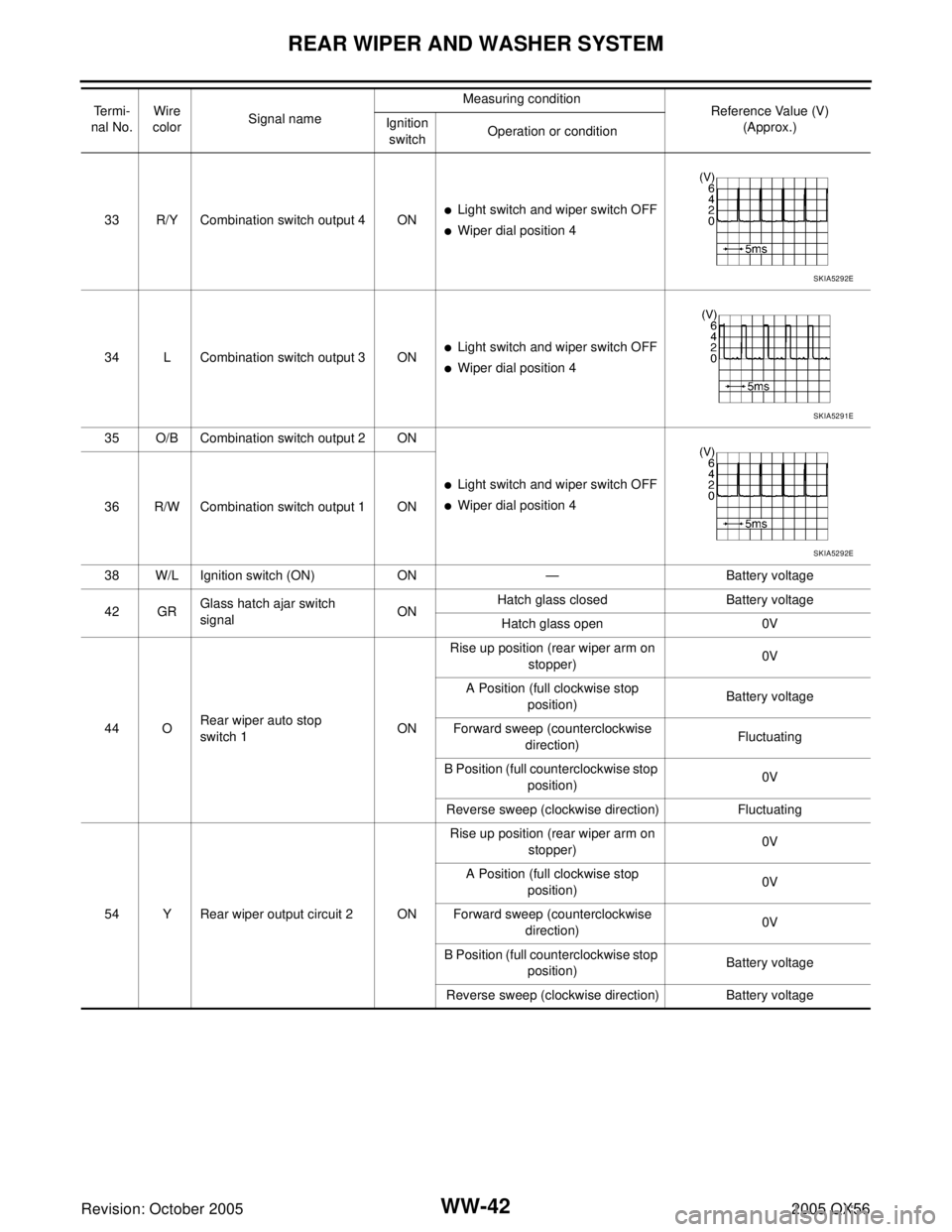
WW-42
REAR WIPER AND WASHER SYSTEM
Revision: October 20052005 QX56
33 R/Y Combination switch output 4 ON�Light switch and wiper switch OFF
�Wiper dial position 4
34 L Combination switch output 3 ON
�Light switch and wiper switch OFF
�Wiper dial position 4
35 O/B Combination switch output 2 ON
�Light switch and wiper switch OFF
�Wiper dial position 4
36 R/W Combination switch output 1 ON
38 W/L Ignition switch (ON) ON — Battery voltage
42 GRGlass hatch ajar switch
signalONHatch glass closed Battery voltage
Hatch glass open 0V
44 ORear wiper auto stop
switch 1ONRise up position (rear wiper arm on
stopper)0V
A Position (full clockwise stop
position)Battery voltage
Forward sweep (counterclockwise
direction)Fluctuating
B Position (full counterclockwise stop
position)0V
Reverse sweep (clockwise direction) Fluctuating
54 Y Rear wiper output circuit 2 ONRise up position (rear wiper arm on
stopper)0V
A Position (full clockwise stop
position)0V
Forward sweep (counterclockwise
direction)0V
B Position (full counterclockwise stop
position)Battery voltage
Reverse sweep (clockwise direction) Battery voltage Te r m i -
nal No.Wire
colorSignal nameMeasuring condition
Reference Value (V)
(Approx.) Ignition
switchOperation or condition
SKIA5292E
SKIA5291E
SKIA5292E