Page 3127 of 3419
SRS-48
SPIRAL CABLE
Revision: October 20052005 QX56
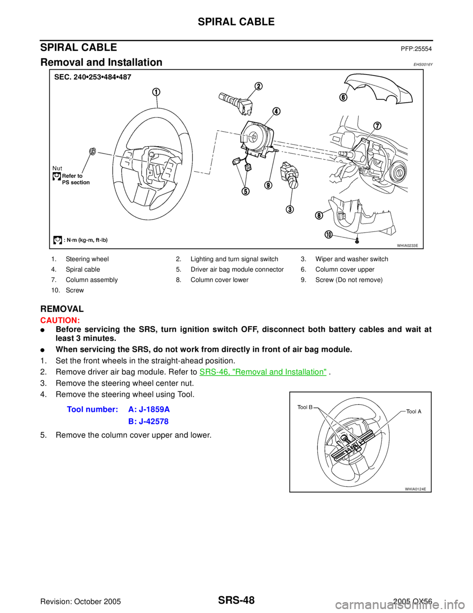
SPIRAL CABLEPFP:25554
Removal and InstallationEHS0016Y
REMOVAL
CAUTION:
�Before servicing the SRS, turn ignition switch OFF, disconnect both battery cables and wait at
least 3 minutes.
�When servicing the SRS, do not work from directly in front of air bag module.
1. Set the front wheels in the straight-ahead position.
2. Remove driver air bag module. Refer to SRS-46, "
Removal and Installation" .
3. Remove the steering wheel center nut.
4. Remove the steering wheel using Tool.
5. Remove the column cover upper and lower.
WHIA0233E
1. Steering wheel 2. Lighting and turn signal switch 3. Wiper and washer switch
4. Spiral cable 5. Driver air bag module connector 6. Column cover upper
7. Column assembly 8. Column cover lower 9. Screw (Do not remove)
10. Screw
Tool number: A: J-1859A
B: J-42578
WHIA0124E
Page 3128 of 3419

SPIRAL CABLE
SRS-49
C
D
E
F
G
I
J
K
L
MA
B
SRS
Revision: October 20052005 QX56
6. Remove wiper washer switch connector, then pinch the tabs at
wiper and washer switch base and slide switch away from steer-
ing column to remove.
7. While pressing tabs, pull lighting and turn signal switch toward
driver door and disconnect from base.
8. Remove the screws, release the clip, and remove the spiral
cable.
CAUTION:
�Do not disassemble spiral cable.
�Do not apply lubricant to the spiral cable.
9. Remove the spiral cable connectors.
CAUTION:
With the steering linkage disconnected, the spiral cable may snap by turning the steering wheel
beyond the limited number of turns. The spiral cable can be turned counterclockwise about 2.5
turns from the neutral position.
INSTALLATION
Installation is in the reverse order of removal.
�Align spiral cable correctly when installing steering wheel. Make
sure that the spiral cable is in the neutral position. The neutral
position is detected by turning left 2.6 revolutions from the right
end position and ending with the knob at the top.
�If equipped with VDC, refer to BRC-62, "Adjustment of Steering
Angle Sensor Neutral Position" for steering angle sensor adjust-
ment.
�After the work is completed, perform self-diagnosis to make sure
no malfunction is detected. Refer to SRS-20, "
SRS Operation
Check" .
LHIA0034E
LHIA0035E
LHIA0036E
WGIA0038E
Page 3178 of 3419

TROUBLE DIAGNOSIS
TF-35
C
E
F
G
H
I
J
K
L
MA
B
TF
Revision: October 20052005 QX56
NOTE:
�Light tight-corner braking symptom may occur depending on driving conditions in AUTO mode. This is not
a malfunction.
�Heavy tight-corner braking symptom occurs when vehicle is driven in the following conditions: 4WD shift
switch is "4H" or "4LO", steering wheel is turned fully to either side.
4WD shift indicator lamp or 4LO indicator
lamp does not changeEngine running4WD shift switch
TF-123
Wait detection switch
Neutral-4LO switch
ATP switch
2-4WD solenoid
Transfer control device
Actuator motor
Actuator position switch
Transfer inner parts
ATP warning lamp turns ON Engine runningCAN communication line
TF-125
4WD shift switch
PNP switch signal
ATP switch
Combination meter
Transfer inner parts
4LO indicator lamp repeats flashing Engine runningWait detection switch
TF-127
Neutral-4LO switch
Transfer inner parts
4WD warning lamp flashes rapidly (2 times/
second)While drivingTransfer fluid temperature
TF-128
Tire size is different between front and
rear of vehicle
4WD warning lamp flashes slowly
(1 time/2 seconds)While drivingTire size is different between front and
rear of vehicle.
TF-129
Transfer fluid temperature
Clutch pressure switch
Heavy tight-corner braking symptom occurs
(See NOTE.)
�While driving
�AUTO mode
�Steering wheel is
turned fully to either
sideCAN communication line
TF-130
4WD shift switch
Accelerator pedal position signal
Clutch pressure solenoid
Transfer inner parts
4WD system does not operate While driving4WD shift switch
TF-131
Clutch pressure switch
Transfer inner parts Symptom Condition Check item Reference page
Page 3192 of 3419

TROUBLE DIAGNOSIS
TF-49
C
E
F
G
H
I
J
K
L
MA
B
TF
Revision: October 20052005 QX56
WORK SUPPORT
When there is no problem with transfer and 4WD system, following symptom in “AUTO” mode may be claimed
by a customer.
�Vibration when accelerating on a low µ road (snow-covered or icy road)
It is possible to deal with these symptoms by changing “CLUTCH FORCE RELEASE LIMIT VALUE”.
However, be careful when changing the values because it may adversely affect driving performance.
NOTE:
A slight shock is felt at a few hertz as if it were being pushed lightly from behind.
Operation Procedure
1. Perform “CONSULT-II SETTING PROCEDURE”. Refer to TF-44, "CONSULT-II SETTING PROCEDURE"
.
2. Touch “WORK SUPPORT”.
3. Select from “CLUTCH/F RLS LIM ADJ”, screen of data monitor mode is displayed.
T/F F SPEED [km/h] or [mph]×–×Displayed, but do not use.
A/T R SPEED [km/h] or [mph]×–×Output shaft revolution signal (Revolution
sensor) calculated by TCM.
Signal input with CAN communication line.
AT GEAR POSI [1/2/3/4/5]×–×A/T actual gear position is displayed.
Voltage [V] – –×The value measured by the voltage probe is
displayed.
Frequency [Hz] – –×
The value measured by the pulse probe is
displayed. DUTY-HI (high) [%] – –×
DUTY-LOW (low) [%] – –×
PLS WIDTH-HI [msec] – –×
PLS WIDTH-LOW [msec] – –× Monitored item (Unit)Monitor item selection
Remarks
ECU INPUT
SIGNALSMAIN
SIGNALSSELEC-
TION FROM
MENU
Page 3273 of 3419

TF-130
TROUBLE DIAGNOSIS FOR SYMPTOMS
Revision: October 20052005 QX56
Heavy Tight-corner Braking Symptom OccursEDS002HT
SYMPTOM:
Heavy tight-corner braking symptom occurs when vehicle is driven in AUTO mode and steering wheel
is turned fully to either side.
DIAGNOSTIC PROCEDURE
NOTE:
�Light tight-corner braking symptom may occur depending on driving conditions in AUTO mode. This is not
a malfunction.
�Heavy tight-corner braking symptom occurs when vehicle is driven in the following conditions: 4WD shift
switch is "4H" or "4LO", steering wheel is turned fully to either side.
1. CHECK SYSTEM FOR CAN COMMUNICATION LINE
Perform self-diagnosis. Refer to TF-50, "
SELF-DIAGNOSTIC PROCEDURE (WITH CONSULT-II)" .
Is "CAN COMM CIRCUIT [U1000]" displayed?
YES >> Perform trouble diagnosis for CAN communication line. Refer to TF-113, "CAN Communication
Line" .
NO >> GO TO 2.
2. CHECK SYSTEM FOR 4WD SHIFT SWITCH
Perform trouble diagnosis for 4WD shift switch system. Refer to TF-62, "
4WD Shift Switch" .
OK or NG
OK >> GO TO 3.
NG >> Repair or replace damaged parts.
3. CHECK ACCELERATOR PEDAL POSITION SIGNAL CIRCUIT
Perform self diagnosis for ECM. Refer to EC-49, "
Emission-related Diagnostic Information" .
Is any malfunction detected by self-diagnosis?
YES >> Check the malfunctioning system.
NO >> GO TO 4.
4. CHECK SYSTEM FOR CLUTCH PRESSURE SOLENOID
Perform trouble diagnosis for clutch pressure solenoid system. Refer to TF-105, "
Clutch Pressure Switch" .
OK or NG
OK >> GO TO 5.
NG >> Repair or replace damaged parts.
5. SYMPTOM CHECK
Check again.
OK or NG
OK >> Inspection End.
NG >> GO TO 6.
6. CHECK TRANSFER CONTROL UNIT
Check transfer control unit input/output signal. Refer to TF-36, "
Transfer Control Unit Input/Output Signal Ref-
erence Values" .
OK or NG
OK >> GO TO 7.
NG >> Check transfer control unit pin terminals for damage or loose connection with harness connector.
If any items are damaged, repair or replace damaged parts.
Page 3321 of 3419

TF-178
TRANSFER ASSEMBLY
Revision: October 20052005 QX56
18. Apply liquid gasket to the entire center case mounting surface of
the front case assembly as shown.
�Use Genuine Anaerobic Liquid Gasket or equivalent.
Refer to GI-45, "
Recommended Chemical Products and
Sealants" .
CAUTION:
Remove all foreign materials such as water, oil and grease
from center case and front case mating surfaces.
19. Install the center case assembly to the front case assembly.
CAUTION:
Do not damage mainshaft end.
20. Tap the center case lightly and press-fit the front drive shaft
bearing into the front case.
21. Tighten the front case bolts to the specified torque. Refer to TF-
144, "COMPONENTS" .
CAUTION:
Be sure to install air breather hose clamp, connector
bracket and harness clip.
22. Install the drain plug with a new gasket.
CAUTION:
Do not reuse gasket.
23. Align the matching mark on the front drive shaft with the mark on
the companion flange, then install the companion flange.
WDIA0157E
SDIA2138E
SDIA2100E
SDIA2779E
Page 3368 of 3419
FRONT WIPER AND WASHER SYSTEM
WW-9
C
D
E
F
G
H
I
J
L
MA
B
WW
Revision: October 20052005 QX56
NOTE:
Each OUTPUT terminal transistor is activated at 10 ms intervals. Therefore, after the switch is turned ON,
electrical loads are activated with time delay. This time delay is so short that it cannot be detected by human
senses.
Operation Mode
The combination switch reading function has the operation modes shown below.
1. Normal status
–When BCM is not in sleep status, OUTPUT terminals (1-5) each turn ON-OFF every 10 ms.
2. Sleep status
–When BCM is in sleep status, transistors of OUTPUT 1 stop the output, and BCM enters low current con-
sumption mode. OUTPUT (2, 3, and 4) turn ON-OFF every 10 ms, and only input from light switch system
is accepted.
CAN Communication System DescriptionEKS00BDU
Refer to LAN-5, "CAN COMMUNICATION" .
SKIA4961E
Page 3373 of 3419

(Appr")
WW-14
FRONT WIPER AND WASHER SYSTEM
Revision: October 20052005 QX56
Terminals and Reference Values for BCMEKS00BDX
Te r m i -
nal No.Wire
colorSignal nameMeasuring condition
Reference Value (V)
(Approx.) Ignition
switchOperation or condition
2 SB Combination switch input 5 ON
�Light switch and wiper switch OFF
�Wiper dial position 4
3 G/Y Combination switch input 4 ON
�Light switch and wiper switch OFF
�Wiper dial position 4
4 Y Combination switch input 3 ON
�Light switch and wiper switch OFF
�Wiper dial position 4
5 G/B Combination switch input 2
ON
�Light switch and wiper switch OFF
�Wiper dial position 4
6 V Combination switch input 1
32 R/G Combination switch output 5 ON
�Light switch and wiper switch OFF
�Wiper dial position 4
33 R/Y Combination switch output 4 ON
�Light switch and wiper switch OFF
�Wiper dial position 4
34 L Combination switch output 3 ON
�Light switch and wiper switch OFF
�Wiper dial position 4
SKIA5291E
SKIA5292E
SKIA5291E
SKIA5292E
SKIA5291E
SKIA5292E
SKIA5291E