Page 2073 of 3419

FL-8Revision: October 2005
FUEL LEVEL SENSOR UNIT, FUEL FILTER AND FUEL PUMP ASSEMBLY
2005 QX56
11. Remove the lock ring using Tool.
12. Remove the fuel level sensor, fuel filter, and fuel pump assem-
bly.
CAUTION:
�Do not bend the float arm during removal.
�Avoid impacts such as dropping when handling the com-
ponents.
INSTALLATION
Installation is in the reverse order of removal.
�Connect the quick connector as follows:
–Check the connection for any damage or foreign materials.
–Align the connector with the pipe, then insert the connector straight into the pipe until a click is heard.
–After connecting the quick connector, make sure that the con-
nection is secure by checking as follows:
–Pull the tube and the connector to make sure they are securely
connected.
–Visually inspect the connector to make sure the two retainer tabs
are securely connected.
INSPECTION AFTER INSTALLATION
1. Turn the ignition switch ON but do not start engine, then check the fuel pipes and hose connections for
leaks while applying fuel pressure to the system.
2. Start the engine and rev it above idle speed, then check that there are no fuel leaks at any of the fuel pipe
and hose connections.Tool number : — (J-46536)
LBIA0389E
PBIC1653E
Page 2074 of 3419
FUEL TANK
FL-9
C
D
E
F
G
H
I
J
K
L
MA
FL
Revision: October 20052005 QX56
FUEL TANKPFP:17202
Removal and InstallationEBS00M3T
1. Inspection hole cover 2. Inspection hole cover O-ring 3. Lock ring
4. Fuel level sensor, fuel filter, and fuel
pump assembly5. Fuel tank 6. Fuel tank protector
7. Fuel tank protector clips 8. Fuel tank straps 9. Fuel level sensor, fuel filter, and fuel
pump assembly O-ring
WBIA0443E
Page 2076 of 3419
FUEL TANK
FL-11
C
D
E
F
G
H
I
J
K
L
MA
FL
Revision: October 20052005 QX56
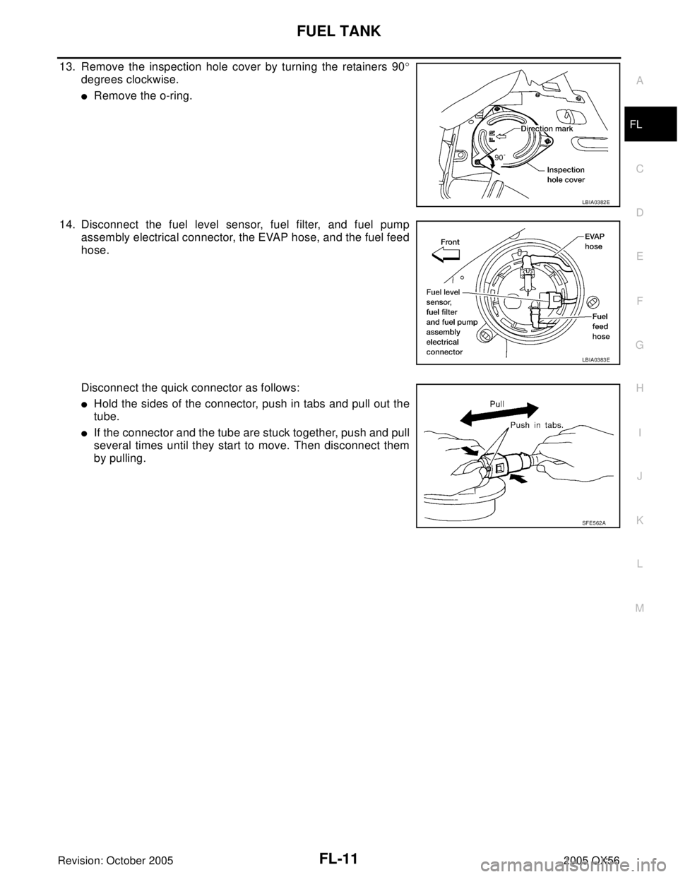
13. Remove the inspection hole cover by turning the retainers 90°
degrees clockwise.
�Remove the o-ring.
14. Disconnect the fuel level sensor, fuel filter, and fuel pump
assembly electrical connector, the EVAP hose, and the fuel feed
hose.
Disconnect the quick connector as follows:
�Hold the sides of the connector, push in tabs and pull out the
tube.
�If the connector and the tube are stuck together, push and pull
several times until they start to move. Then disconnect them
by pulling.
LBIA0382E
LBIA0383E
SF E5 62 A
Page 2078 of 3419

FUEL TANK
FL-13
C
D
E
F
G
H
I
J
K
L
MA
FL
Revision: October 20052005 QX56
19. Remove the fuel tank strap bolts while supporting the fuel tank
with a suitable lift jack.
20. Disconnect the EVAP hose from the molded clip in the top of the fuel tank while lowering the fuel tank.
21. Lower the fuel tank using a suitable lift jack and remove it.
22. If necessary, remove the lock ring using Tool.
23. If necessary, remove the fuel level sensor, fuel filter, and fuel
pump assembly.
CAUTION:
�Do not bend the float arm during removal.
�Avoid impacts such as dropping when handling the com-
ponents.
INSTALLATION
Installation is in the reverse order of removal.
�Connect the quick connector as follows:
–Check the connection for any damage or foreign materials.
–Align the connector with the pipe, then insert the connector straight into the pipe until a click is heard.
–After connecting the quick connector, make sure that the con-
nection is secure by checking as follows:
–Pull the tube and the connector to make sure they are securely
connected.
–Visually inspect the connector to make sure the two retainer tabs
are securely connected.
INSPECTION AFTER INSTALLATION
1. Turn the ignition switch ON but do not start engine, then check the fuel pipe and hose connections for
leaks while applying fuel pressure.
2. Start the engine and rev it above idle, then check that there are no fuel leaks at any of the fuel pipe and
hose connections.
LBIA0387E
Tool number : — (J-46536)
LBIA0389E
PBIC1653E
Page 2081 of 3419
FSU-2
PRECAUTIONS
Revision: October 20052005 QX56
PRECAUTIONSPFP:00001
PrecautionsEES001GD
�When installing the rubber bushings, the final tightening must be done under unladen condition and with
the tires on level ground. Oil will shorten the life of the rubber bushings, so wipe off any spilled oil immedi-
ately.
�Unladen condition means the fuel tank, engine coolant and lubricants are at the full specification. The
spare tire, jack, hand tools, and mats are in their designated positions.
�After installing suspension components, check the wheel alignment.
�Lock nuts are not reusable. Always use new lock nuts for installation. New lock nuts are pre-oiled, do not
apply any additional lubrication.
Page 2087 of 3419
.
2. Push the vehicle straight ahead about 5 m (16 ft).
3.")
FSU-8
ON-VEHICLE SERVICE
Revision: October 20052005 QX56
1. Bounce the front of vehicle up and down to stabilize the vehicle height (posture).
2. Push the vehicle straight ahead about 5 m (16 ft).
3. Put a mark on base line of the tread (rear side) of both front tires
at the same height as hub center as shown. These marks are
measuring points.
4. Measure the distance “A” on the rear side of the front tires as
shown.
5. Push the vehicle slowly ahead to rotate the wheels 180°
degrees (1/2 a turn).
CAUTION:
If the wheels have rotated more than 180° degrees (1/2
turn), start this procedure again from the beginning. Never
push the vehicle backward.
6. Measure the distance “B” on the front side of the front tires at the
same marks as shown. Total toe-in is calculated as “A” – “B”.
7. Adjust the toe-in by varying the length of the steering outer
socket.
a. Loosen the outer tie-rod lock nuts.
b. Adjust the toe-in by screwing the outer tie-rods in or out.
c. Tighten the outer tie-rod lock nuts to specification.
FRONT WHEEL TURNING ANGLE
NOTE:
Check front wheel turning angle after the toe-in inspection.
1. Place front wheels on turning radius gauges in straight ahead
position and rear wheels on stands so that vehicle can be level.
Check the maximum inner and outer wheel turning angles for LH
and RH road wheels.
2. Start engine and run at idle, turn steering wheel all the way right
and left, measure the turning angle.
�Any turning angles are not adjustable. If any of steering
angles are out of the specification, check if the following parts
are worn or damaged.
–Steering gear
–Steering column
–Front suspension components
AFA05 0
Total toe-in : Refer to FSU-20, "Wheel Alignment
(Unladen*1 )*6" .
SFA234AC
Standard length “L” : Refer to PS-34, "Steering Outer
Socket and Inner Socket" .
Lock nut : Refer to PS-17, "
Disassembly and
Assembly" .SGIA0167E
Wheel turning angle
(full turn): Refer to FSU-20, "Wheel
Alignment (Unladen*1 )*6" .
SFA439BA
Page 2089 of 3419

FSU-10
COIL SPRING AND SHOCK ABSORBER
Revision: October 20052005 QX56
COIL SPRING AND SHOCK ABSORBERPFP:56210
Removal and InstallationEES001GK
REMOVAL
1. Remove the wheel and tire using power tool.
2. Remove the shock absorber lower bolt using power tool.
3. Remove the three shock absorber upper mounting nuts using
power tool.
4. Remove the coil spring and shock absorber assembly.
�Turn steering knuckle out to gain enough clearance for
removal.
INSTALLATION
Installation is in the reverse order of removal.
�The step in the shock absorber assembly lower seat faces outside of vehicle.
�Tighten all nuts and bolts to specification. Refer to FSU-5, "Components" .
�When installing wheel and tire, refer to WT-7, "Rotation" .
Disassembly and AssemblyEES001GL
DISASSEMBLY
1. Set the shock absorber in a vise, then loosen (without removing)
the piston rod lock nut as shown.
CAUTION:
Do not remove piston rod lock nut at this time.
2. Compress the spring using commercial service tool until the
shock absorber mounting insulator can be turned by hand.
WAR NIN G:
Make sure that the pawls of the two spring compressors are
firmly hooked on the spring. The spring compressors must
be tightened alternately and evenly so as not to tilt the
spring.
3. Remove the piston rod lock nut.
�Discard the piston rod lock nut, use a new nut for assembly.
INSPECTION AFTER DISASSEMBLY
Shock Absorber Assembly
�Check for smooth operation through a full stroke, both compression and extension.
�Check for oil leakage on welded or gland packing portions.
�Check piston rod for cracks, deformation or other damage and replace if necessary.
Mounting Insulator and Rubber Parts
Check cemented rubber-to-metal portion for separation or cracks. Check rubber parts for deterioration and
replace if necessary.
LEIA0093E
SSU0 02
SSU0 03
Page 2090 of 3419
COIL SPRING AND SHOCK ABSORBER
FSU-11
C
D
F
G
H
I
J
K
L
MA
B
FSU
Revision: October 20052005 QX56
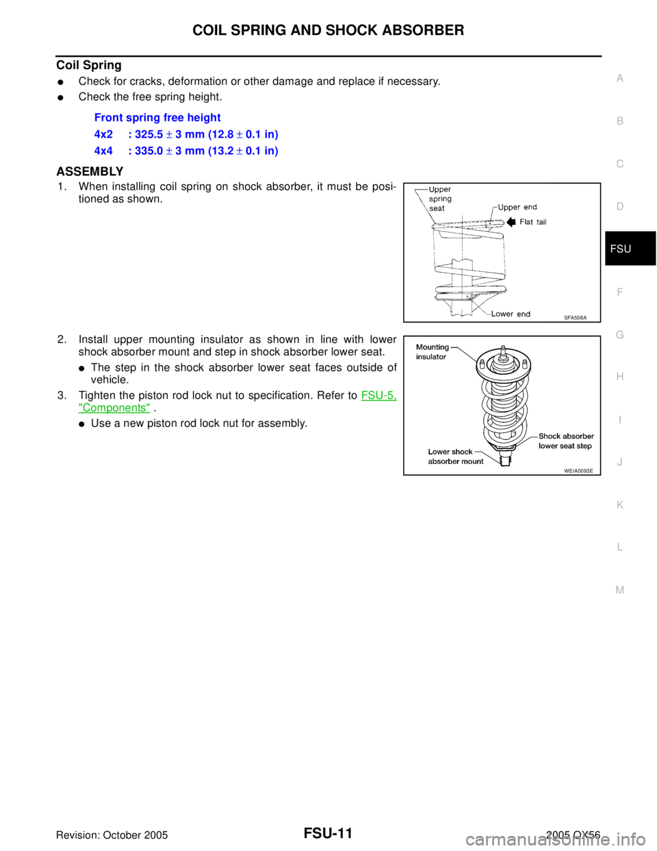
Coil Spring
�Check for cracks, deformation or other damage and replace if necessary.
�Check the free spring height.
ASSEMBLY
1. When installing coil spring on shock absorber, it must be posi-
tioned as shown.
2. Install upper mounting insulator as shown in line with lower
shock absorber mount and step in shock absorber lower seat.
�The step in the shock absorber lower seat faces outside of
vehicle.
3. Tighten the piston rod lock nut to specification. Refer to FSU-5,
"Components" .
�Use a new piston rod lock nut for assembly.Front spring free height
4x2 : 325.5 ± 3 mm (12.8 ± 0.1 in)
4x4 : 335.0 ± 3 mm (13.2 ± 0.1 in)
SFA508A
WEIA0093E