Page 1655 of 3419
EC-464Revision: October 2005
DTC P1271, P1281 A/F SENSOR 1
2005 QX56
Specification data are reference values and are measured between each terminal and ground.
CAUTION:
Do not use ECM ground terminals when measuring input/output voltage. Doing so may result in dam-
age to the ECM's transistor. Use a ground other than ECM terminals, such as the ground.
Diagnostic ProcedureUBS00H9K
1. CHECK GROUND CONNECTIONS
1. Turn ignition switch OFF.
2. Loosen and retighten three ground screws on the body.
Refer to EC-162, "
Ground Inspection" .
OK or NG
OK >> GO TO 2.
NG >> Repair or replace ground connections.
TER-
MINAL
NO.WIRE
COLORITEM CONDITION DATA (DC Voltage)
57 L/P
A/F sensor 1 (bank 2)[Engine is running]
�Warm-up condition
�Idle speedApproximately 2.6V
58 GR/GApproximately 2.3V
76 G/LApproximately 3.1V
77 BR/BApproximately 2.3V
BBIA0354E
Page 1659 of 3419
EC-468Revision: October 2005
DTC P1272, P1282 A/F SENSOR 1
2005 QX56
DTC P1272, P1282 A/F SENSOR 1PFP:22693
Component DescriptionUBS00H9M
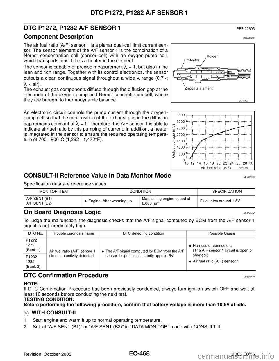
The air fuel ratio (A/F) sensor 1 is a planar dual-cell limit current sen-
sor. The sensor element of the A/F sensor 1 is the combination of a
Nernst concentration cell (sensor cell) with an oxygen-pump cell,
which transports ions. It has a heater in the element.
The sensor is capable of precise measurement = 1, but also in the
lean and rich range. Together with its control electronics, the sensor
outputs a clear, continuous signal throughout a wide range (0.7 <
< air).
The exhaust gas components diffuse through the diffusion gap at the
electrode of the oxygen pump and Nernst concentration cell, where
they are brought to thermodynamic balance.
An electronic circuit controls the pump current through the oxygen-
pump cell so that the composition of the exhaust gas in the diffusion
gap remains constant at = 1. Therefore, the A/F sensor 1 is able to
indicate air/fuel ratio by this pumping of current. In addition, a heater
is integrated in the sensor to ensure the required operating tempera-
ture of 700 - 800°C (1,292 - 1,472°F).
CONSULT-II Reference Value in Data Monitor ModeUBS00H9N
Specification data are reference values.
On Board Diagnosis LogicUBS00H9O
To judge the malfunction, the diagnosis checks that the A/F signal computed by ECM from the A/F sensor 1
signal is not inordinately high.
DTC Confirmation ProcedureUBS00H9P
NOTE:
If DTC Confirmation Procedure has been previously conducted, always turn ignition switch OFF and wait at
least 10 seconds before conducting the next test.
TESTING CONDITION:
Before performing the following procedure, confirm that battery voltage is more than 10.5V at idle.
WITH CONSULT-II
1. Start engine and warm it up to normal operating temperature.
2. Select “A/F SEN1 (B1)” or “A/F SEN1 (B2)” in “DATA MONITOR” mode with CONSULT-II.
SEF 5 79 Z
SEF 5 80 Z
MONITOR ITEM CONDITION SPECIFICATION
A/F SEN1 (B1)
A/F SEN1 (B2)
�Engine: After warming upMaintaining engine speed at
2,000 rpmFluctuates around 1.5V
DTC No. Trouble diagnosis name DTC detecting condition Possible Cause
P1272
1272
(Bank 1)
Air fuel ratio (A/F) sensor 1
circuit no activity detected
�The A/F signal computed by ECM from the A/F
sensor 1 signal is constantly approx. 5V.
�Harness or connectors
(The A/F sensor 1 circuit is open or
shorted.)
�Air fuel ratio (A/F) sensor 1 P1282
1282
(Bank 2)
Page 1660 of 3419
DTC P1272, P1282 A/F SENSOR 1
EC-469
C
D
E
F
G
H
I
J
K
L
MA
EC
Revision: October 20052005 QX56
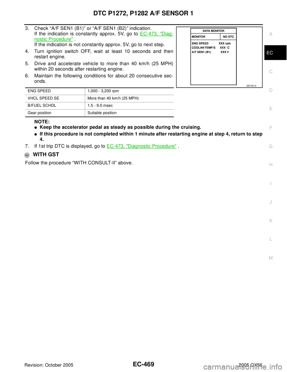
3. Check “A/F SEN1 (B1)” or “A/F SEN1 (B2)” indication.
If the indication is constantly approx. 5V, go to EC-473, "
Diag-
nostic Procedure" .
If the indication is not constantly approx. 5V, go to next step.
4. Turn ignition switch OFF, wait at least 10 seconds and then
restart engine.
5. Drive and accelerate vehicle to more than 40 km/h (25 MPH)
within 20 seconds after restarting engine.
6. Maintain the following conditions for about 20 consecutive sec-
onds.
NOTE:
�Keep the accelerator pedal as steady as possible during the cruising.
�If this procedure is not completed within 1 minute after restarting engine at step 4, return to step
4.
7. If 1st trip DTC is displayed, go to EC-473, "
Diagnostic Procedure" .
WITH GST
Follow the procedure “WITH CONSULT-II” above.
ENG SPEED 1,000 - 3,200 rpm
VHCL SPEED SE More than 40 km/h (25 MPH)
B/FUEL SCHDL 1.5 - 9.0 msec
Gear position Suitable position
SEF 5 81 Z
Page 1664 of 3419
DTC P1272, P1282 A/F SENSOR 1
EC-473
C
D
E
F
G
H
I
J
K
L
MA
EC
Revision: October 20052005 QX56
Specification data are reference values and are measured between each terminal and ground.
CAUTION:
Do not use ECM ground terminals when measuring input/output voltage. Doing so may result in dam-
age to the ECM's transistor. Use a ground other than ECM terminals, such as the ground.
Diagnostic ProcedureUBS00H9R
1. CHECK GROUND CONNECTIONS
1. Turn ignition switch OFF.
2. Loosen and retighten three ground screws on the body.
Refer to EC-162, "
Ground Inspection" .
OK or NG
OK >> GO TO 2.
NG >> Repair or replace ground connections.
TER-
MINAL
NO.WIRE
COLORITEM CONDITION DATA (DC Voltage)
57 L/P
A/F sensor 1 (bank 2)[Engine is running]
�Warm-up condition
�Idle speedApproximately 2.6V
58 GR/GApproximately 2.3V
76 G/LApproximately 3.1V
77 BR/BApproximately 2.3V
BBIA0354E
Page 1673 of 3419
EC-482Revision: October 2005
DTC P1273, P1283 A/F SENSOR 1
2005 QX56
Specification data are reference values and are measured between each terminal and ground.
CAUTION:
Do not use ECM ground terminals when measuring input/output voltage. Doing so may result in dam-
age to the ECM's transistor. Use a ground other than ECM terminals, such as the ground.
Diagnostic ProcedureUBS00H9Y
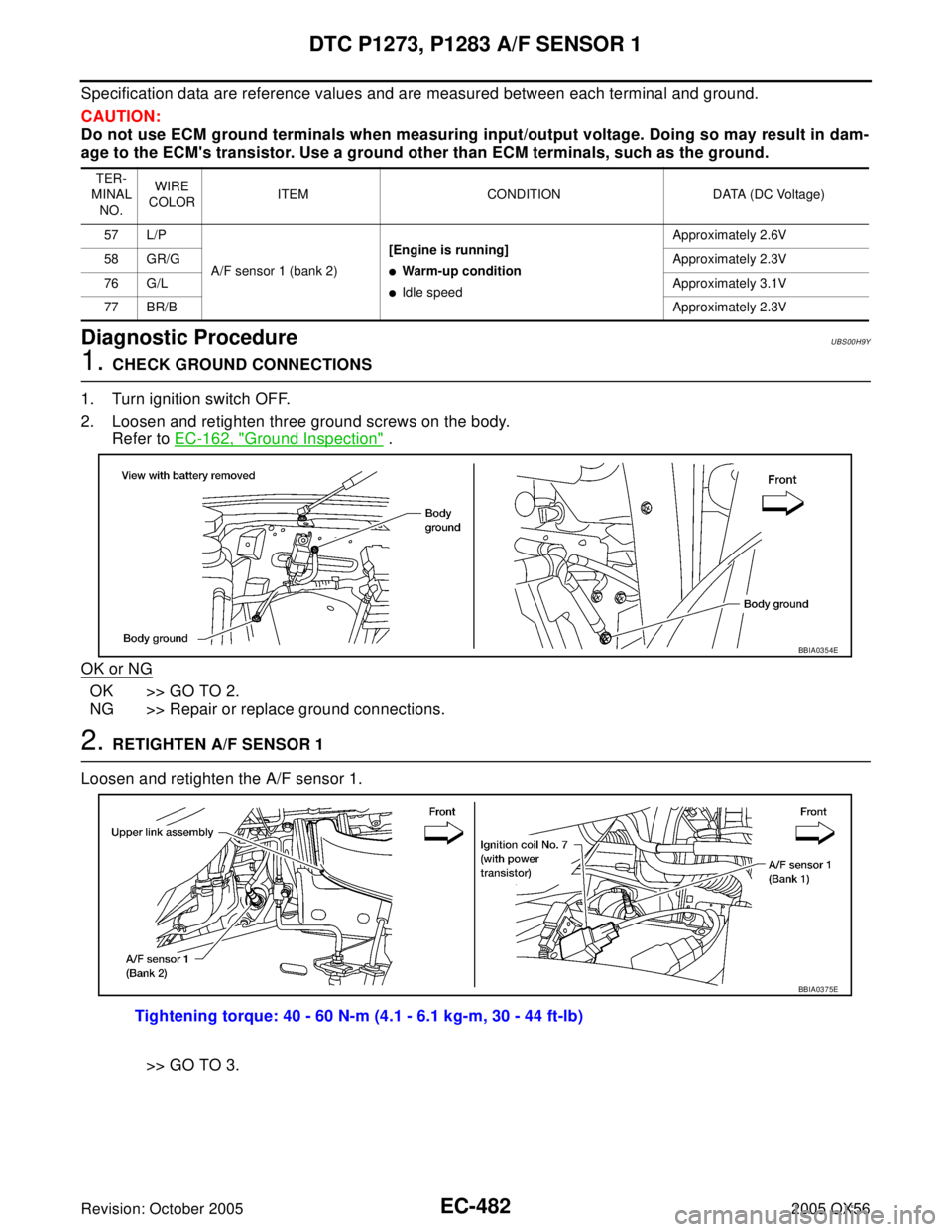
1. CHECK GROUND CONNECTIONS
1. Turn ignition switch OFF.
2. Loosen and retighten three ground screws on the body.
Refer to EC-162, "
Ground Inspection" .
OK or NG
OK >> GO TO 2.
NG >> Repair or replace ground connections.
2. RETIGHTEN A/F SENSOR 1
Loosen and retighten the A/F sensor 1.
>> GO TO 3.
TER-
MINAL
NO.WIRE
COLORITEM CONDITION DATA (DC Voltage)
57 L/P
A/F sensor 1 (bank 2)[Engine is running]
�Warm-up condition
�Idle speedApproximately 2.6V
58 GR/GApproximately 2.3V
76 G/LApproximately 3.1V
77 BR/BApproximately 2.3V
BBIA0354E
Tightening torque: 40 - 60 N-m (4.1 - 6.1 kg-m, 30 - 44 ft-lb)
BBIA0375E
Page 1683 of 3419
EC-492Revision: October 2005
DTC P1274, P1284 A/F SENSOR 1
2005 QX56
Specification data are reference values and are measured between each terminal and ground.
CAUTION:
Do not use ECM ground terminals when measuring input/output voltage. Doing so may result in dam-
age to the ECM's transistor. Use a ground other than ECM terminals, such as the ground.
Diagnostic ProcedureUBS00HA5
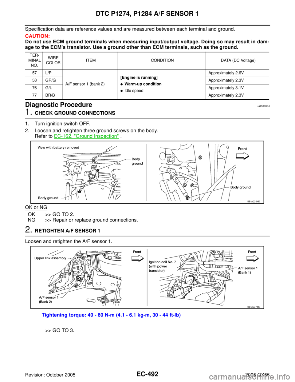
1. CHECK GROUND CONNECTIONS
1. Turn ignition switch OFF.
2. Loosen and retighten three ground screws on the body.
Refer to EC-162, "
Ground Inspection" .
OK or NG
OK >> GO TO 2.
NG >> Repair or replace ground connections.
2. RETIGHTEN A/F SENSOR 1
Loosen and retighten the A/F sensor 1.
>> GO TO 3.
TER-
MINAL
NO.WIRE
COLORITEM CONDITION DATA (DC Voltage)
57 L/P
A/F sensor 1 (bank 2)[Engine is running]
�Warm-up condition
�Idle speedApproximately 2.6V
58 GR/GApproximately 2.3V
76 G/LApproximately 3.1V
77 BR/BApproximately 2.3V
BBIA0354E
Tightening torque: 40 - 60 N-m (4.1 - 6.1 kg-m, 30 - 44 ft-lb)
BBIA0375E
Page 1688 of 3419
DTC P1276, P1286 A/F SENSOR 1
EC-497
C
D
E
F
G
H
I
J
K
L
MA
EC
Revision: October 20052005 QX56
DTC P1276, P1286 A/F SENSOR 1PFP:22693
Component DescriptionUBS00HA7
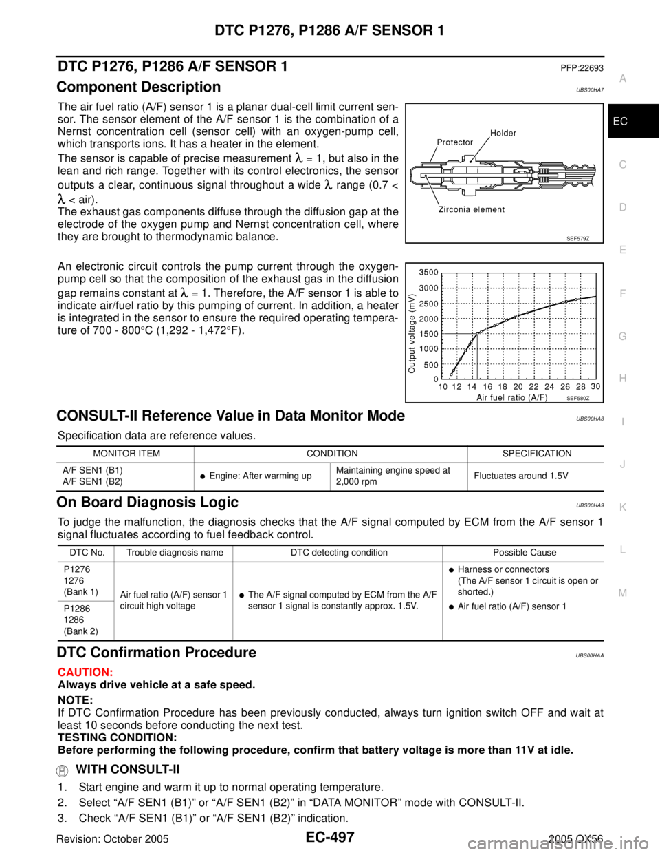
The air fuel ratio (A/F) sensor 1 is a planar dual-cell limit current sen-
sor. The sensor element of the A/F sensor 1 is the combination of a
Nernst concentration cell (sensor cell) with an oxygen-pump cell,
which transports ions. It has a heater in the element.
The sensor is capable of precise measurement = 1, but also in the
lean and rich range. Together with its control electronics, the sensor
outputs a clear, continuous signal throughout a wide range (0.7 <
< air).
The exhaust gas components diffuse through the diffusion gap at the
electrode of the oxygen pump and Nernst concentration cell, where
they are brought to thermodynamic balance.
An electronic circuit controls the pump current through the oxygen-
pump cell so that the composition of the exhaust gas in the diffusion
gap remains constant at = 1. Therefore, the A/F sensor 1 is able to
indicate air/fuel ratio by this pumping of current. In addition, a heater
is integrated in the sensor to ensure the required operating tempera-
ture of 700 - 800°C (1,292 - 1,472°F).
CONSULT-II Reference Value in Data Monitor ModeUBS00HA8
Specification data are reference values.
On Board Diagnosis LogicUBS00HA9
To judge the malfunction, the diagnosis checks that the A/F signal computed by ECM from the A/F sensor 1
signal fluctuates according to fuel feedback control.
DTC Confirmation ProcedureUBS00HAA
CAUTION:
Always drive vehicle at a safe speed.
NOTE:
If DTC Confirmation Procedure has been previously conducted, always turn ignition switch OFF and wait at
least 10 seconds before conducting the next test.
TESTING CONDITION:
Before performing the following procedure, confirm that battery voltage is more than 11V at idle.
WITH CONSULT-II
1. Start engine and warm it up to normal operating temperature.
2. Select “A/F SEN1 (B1)” or “A/F SEN1 (B2)” in “DATA MONITOR” mode with CONSULT-II.
3. Check “A/F SEN1 (B1)” or “A/F SEN1 (B2)” indication.
SEF 5 79 Z
SEF 5 80 Z
MONITOR ITEM CONDITION SPECIFICATION
A/F SEN1 (B1)
A/F SEN1 (B2)
�Engine: After warming upMaintaining engine speed at
2,000 rpmFluctuates around 1.5V
DTC No. Trouble diagnosis name DTC detecting condition Possible Cause
P1276
1276
(Bank 1)
Air fuel ratio (A/F) sensor 1
circuit high voltage
�The A/F signal computed by ECM from the A/F
sensor 1 signal is constantly approx. 1.5V.
�Harness or connectors
(The A/F sensor 1 circuit is open or
shorted.)
�Air fuel ratio (A/F) sensor 1
P1286
1286
(Bank 2)
Page 1689 of 3419
EC-498Revision: October 2005
DTC P1276, P1286 A/F SENSOR 1
2005 QX56
If the indication is constantly approx. 1.5V and does not fluctuates, go to EC-503, "Diagnostic Procedure" .
If the indication fluctuates around 1.5V, go to next step.
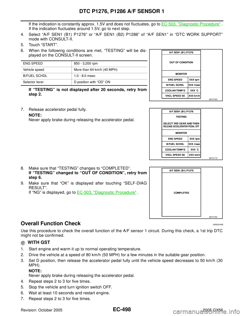
4. Select “A/F SEN1 (B1) P1276” or “A/F SEN1 (B2) P1286” of “A/F SEN1” in “DTC WORK SUPPORT”
mode with CONSULT-II.
5. Touch “START”.
6. When the following conditions are met, “TESTING” will be dis-
played on the CONSULT-II screen.
If “TESTING” is not displayed after 20 seconds, retry from
step 2.
7. Release accelerator pedal fully.
NOTE:
Never apply brake during releasing the accelerator pedal.
8. Make sure that “TESTING” changes to “COMPLETED”.
If “TESTING” changed to “OUT OF CONDITION”, retry from
step 6.
9. Make sure that “OK” is displayed after touching “SELF-DIAG
RESULT”.
If “NG” is displayed, go to EC-503, "
Diagnostic Procedure" .
Overall Function CheckUBS00HAB
Use this procedure to check the overall function of the A/F sensor 1 circuit. During this check, a 1st trip DTC
might not be confirmed.
WITH GST
1. Start engine and warm it up to normal operating temperature.
2. Drive the vehicle at a speed of 80 km/h (50 MPH) for a few minutes in the suitable gear position.
3. Set D position, then release the accelerator pedal fully until the vehicle speed decreases to 50 km/h (30
MPH).
NOTE:
Never apply brake during releasing the accelerator pedal.
4. Repeat steps 2 to 3 for five times.
5. Stop the vehicle and turn ignition switch OFF.
6. Wait at least 10 seconds and restart engine.
7. Repeat steps 2 to 3 for five times.
ENG SPEED 850 - 3,200 rpm
Vehicle speed More than 64 km/h (40 MPH)
B/FUEL SCHDL 1.0 - 8.0 msec
Selector lever D position with “OD” ON
SEF 5 76 Z
SEF 5 77 Z
SEF 5 78 Z