Page 1093 of 3419

CO-12Revision: October 2005
RADIATOR
2005 QX56
RADIATORPFP:21400
Removal and InstallationEBS00LN7
WAR NIN G:
Never remove the radiator cap when the engine is hot. Serious burns could occur from high-pressure
engine coolant escaping from the radiator.
REMOVAL
CAUTION:
Perform when the engine is cold.
1. Remove engine room cover. Refer to EM-11, "
ENGINE ROOM COVER" .
2. Drain engine coolant from the radiator. Refer to MA-13, "
DRAINING ENGINE COOLANT" .
3. Remove air cleaner and air duct assembly. Refer to EM-14, "
REMOVAL" .
4. Disconnect A/T fluid cooler hoses.
�Install blind plug to avoid leakage of A/T fluid.
5. Disconnect radiator upper and lower hoses from radiator.
CAUTION:
Do not allow coolant to contact drive belts.
WBIA0519E
1. Radiator 2. Bolt 3. Mounting rubber
4. A/T fluid cooler hose 5. Radiator hose (lower) 6. Flaps
7. Radiator shroud (upper) 8. Radiator shroud (lower) 9. Drain plug
10. Radiator hose (upper) 11. Reservoir tank hose 12. By-pass hose
13. Reservoir tank 14. Reservoir tank cap
Page 1094 of 3419
RADIATOR
CO-13
C
D
E
F
G
H
I
J
K
L
MA
CO
Revision: October 20052005 QX56
6. Remove the lower radiator shroud.
�Release the tabs, pull lower radiator shroud rearwards and
down to remove.
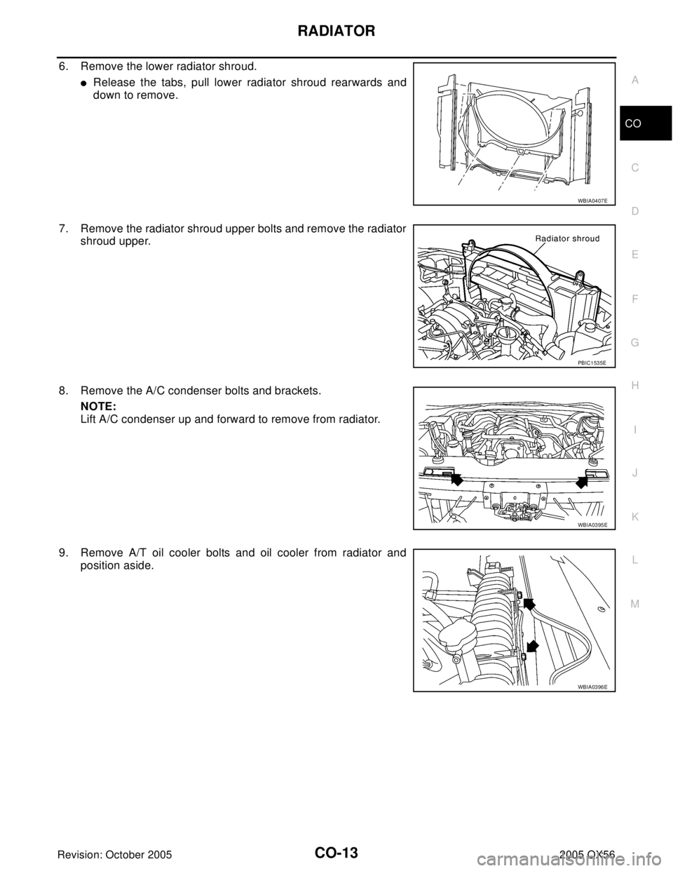
7. Remove the radiator shroud upper bolts and remove the radiator
shroud upper.
8. Remove the A/C condenser bolts and brackets.
NOTE:
Lift A/C condenser up and forward to remove from radiator.
9. Remove A/T oil cooler bolts and oil cooler from radiator and
position aside.
WBIA0407E
PBIC1535E
WBIA0395E
WBIA0396E
Page 1095 of 3419

CO-14Revision: October 2005
RADIATOR
2005 QX56
10. Lift up and remove the radiator.
CAUTION:
Do not damage or scratch air conditioner condenser and
radiator core when removing.
INSTALLATION
Installation is in the reverse order of removal.
INSPECTION AFTER INSTALLATION
�Check for leaks of engine coolant. Refer to CO-10, "CHECKING COOLING SYSTEM FOR LEAKS" .
�Start and warm up the engine. Visually check for leaks of the engine coolant and A/T fluid.
Checking RadiatorEBS00LN9
Check radiator for mud or clogging. If necessary, clean radiator as follows.
CAUTION:
�Be careful not to bend or damage the radiator fins.
�When radiator is cleaned without removal, remove all surrounding parts such as cooling fan, radi-
ator shroud and horns. Then tape the harness and electrical connectors to prevent water from
entering.
1. Apply water by hose to the back side of the radiator core vertically downward.
2. Apply water again to all radiator core surfaces.
3. Stop washing when dirt and debris no longer flow out from the radiator.
4. Blow air into the back side of radiator core vertically downward.
�Use compressed air lower than 490 kPa (5 kg/cm2 , 71 psi) and keep distance more than 30 cm (11.8
in).
5. Blow air again into all the radiator core surfaces until no water sprays out.
PBIC1536E
Page 1096 of 3419
EBS00LNA
REMOVAL
1. Remove the air duct")
ENGINE COOLING FAN
CO-15
C
D
E
F
G
H
I
J
K
L
MA
CO
Revision: October 20052005 QX56
ENGINE COOLING FANPFP:21140
Removal and Installation (Crankshaft Driven Type)EBS00LNA
REMOVAL
1. Remove the air duct and resonator assembly. Refer to EM-14, "Removal and Installation" .
2. Remove the engine front undercover using power tool.
3. Remove the lower radiator shroud. Refer to CO-12, "
Removal and Installation" .
4. Remove the drive belt. Refer to EM-12, "
Removal and Installation" .
5. Remove the cooling fan.
INSPECTION AFTER REMOVAL
Fan Coupling
Inspect fan coupling for oil leakage and bimetal conditions.
Fan Bracket
�Visually check that there is no significant looseness in the fan
bracket shaft, and that it turns smoothly by hand.
�If there are any unusual concerns, replace the cooling fan pulley.
INSTALLATION
Installation is in the reverse order of removal.
�Install cooling fan with its front mark “F” facing front of engine. Refer to CO-15, "Removal and Installation
(Crankshaft Driven Type)" .
INSPECTION AFTER INSTALLATION
�Check for leaks of the engine coolant. Refer to CO-10, "CHECKING COOLING SYSTEM FOR LEAKS" .
1. Cooling fan 2. Fan coupling 3. Fan bracket
4. Cooling fan pulley
WBIA0632E
SL C0 72
WBIA0418E
Page 1100 of 3419

THERMOSTAT AND WATER PIPING
CO-19
C
D
E
F
G
H
I
J
K
L
MA
CO
Revision: October 20052005 QX56
THERMOSTAT AND WATER PIPINGPFP:21200
Removal and InstallationEBS00LND
REMOVAL
Removal of Thermostat
1. Drain engine coolant from the radiator. Refer to MA-13, "DRAINING ENGINE COOLANT" .
CAUTION:
Perform when engine is cold.
2. Remove the air duct and resonator assembly. Refer to EM-14, "
REMOVAL" .
3. Remove the engine room cover using power tools.
4. Disconnect the water suction hose from the water inlet.
5. Remove the water inlet and thermostat.
Removal of Thermostat Housing, Water Outlet and Heater Pipe
1. Remove the intake manifold. Refer to EM-15, "REMOVAL" .
2. Remove the thermostat housing, water outlet and heater pipe.
Removal of Water Cut Valve
1. Drain the engine coolant from the radiator. Refer to MA-13, "DRAINING ENGINE COOLANT" .
KBIA2501E
1. Heater pipe 2. Gasket 3. Water outlet
4. Gasket 5. O-ring 6. O-ring
7. Thermostat housing 8. Rubber ring 9. Thermostat
10. Water inlet 11. Water suction hose 12. Water suction pipe
13. Gasket 14. Heater pipe
Page 1102 of 3419
SERVICE DATA AND SPECIFICATIONS (SDS)
CO-21
C
D
E
F
G
H
I
J
K
L
MA
CO
Revision: October 20052005 QX56
SERVICE DATA AND SPECIFICATIONS (SDS)PFP:00030
Standard and LimitEBS00LNE
ENGINE COOLANT CAPACITY (APPROXIMATE)
Unit: (US gal, Imp gal)
THERMOSTAT
RADIATOR
Unit: kPa (kg/cm2 , psi)
Engine coolant capacity with reservoir ("MAX" level) 14.4 (3 3/4, 3 1/8)
Valve opening temperature 80 - 84°C (176 - 183°F)
Maximum valve lift More than 10 mm/95°C (0.39 in/203°F)
Valve closing temperature 77°C (171°F) or higher
Reservoir cap relief pressure Standard 95 - 125 (0.97- 1.28, 14 - 18)
Leakage test pressure 137 (1.4, 20)
Page 1211 of 3419

EC-20Revision: October 2005
PREPARATION
2005 QX56
PREPARATIONPFP:00002
Special Service ToolsUBS00KZ4
The actual shapes of Kent-Moore tools may differ from those of special service tools illustrated here.
Tool number
(Kent-Moore No.)
Tool nameDescription
EG17650301
(J-33984-A)
Radiator cap tester
adapterAdapting radiator cap tester to radiator cap and ra-
diator filler neck
a: 28 (1.10) dia.
b: 31.4 (1.236) dia.
c: 41.3 (1.626) dia.
Unit: mm (in)
KV10117100
(J-36471-A)
Heated oxygen sensor
wrenchLoosening or tightening heated oxygen sensors
with 22 mm (0.87 in) hexagon nut
KV10114400
(J-38365)
Heated oxygen sensor
wrenchLoosening or tightening heated oxygen sensors
a: 22 mm (0.87 in)
(J-44626)
Air fuel ratio (A/F) sen-
sor wrenchLoosening or tightening air fuel ratio (A/F) sensor 1
(J-44321)
Fuel pressure gauge
kitChecking fuel pressure
(J-44321-6)
Fuel pressure adapterConnecting fuel pressure gauge to quick connec-
tor type fuel lines.
(J-45488)
Quick connector re-
leaseRemove fuel tube quick connectors in engine
room.
S-NT564
S-NT379
S-NT636
LEM054
LEC642
LBIA0376E
PBIC0198E
Page 1298 of 3419

TROUBLE DIAGNOSIS
EC-107
C
D
E
F
G
H
I
J
K
L
MA
EC
Revision: October 20052005 QX56
1 - 6: The numbers refer to the order of inspection.Exhaust Exhaust manifold/Tube/Muffler/
Gasket
55555 55 5EM-19
, EX-
3Three way catalyst
Lubrica-
tionOil pan/Oil strainer/Oil pump/Oil
filter/Oil gallery/Oil cooler
55555 55 5EM-22
, LU-
13 , LU-10 ,
LU-11
Oil level (Low)/Filthy oilLU-7
Cooling Radiator/Hose/Radiator filler cap
55555 55 45CO-12
Thermostat 5CO-19
Water pum pCO-17
Water galleryCO-8
Cooling fan 5CO-15
Coolant level (Low)/Contami-
nated coolant5CO-10
IVIS (INFINITI Vehicle Immobilizer System —
NATS)11BL-137
SYMPTOM
Reference
page
HARD/NO START/RESTART (EXCP. HA)
ENGINE STALL
HESITATION/SURGING/FLAT SPOT
SPARK KNOCK/DETONATION
LACK OF POWER/POOR ACCELERATION
HIGH IDLE/LOW IDLE
ROUGH IDLE/HUNTING
IDLING VIBRATION
SLOW/NO RETURN TO IDLE
OVERHEATS/WATER TEMPERATURE HIGH
EXCESSIVE FUEL CONSUMPTION
EXCESSIVE OIL CONSUMPTION
BATTERY DEAD (UNDER CHARGE)
Warranty symptom code AA AB AC AD AE AF AG AH AJ AK AL AM HA

CO-21
C
D
E
F
G
H
I
J
K
L
MA
CO
Revision: October 20052005 QX56
SERVICE DATA AND SPECIFICATIONS (SDS)PFP:00030
Standard and LimitEBS00LNE
ENGINE COOLANT CAPACITY")