Page 2751 of 3419
PG-76
FUSE BLOCK-JUNCTION BOX(J/B)
Revision: October 20052005 QX56
FUSE BLOCK-JUNCTION BOX(J/B)PFP:24350
Terminal ArrangementEKS00BNN
WKIA2016E
Page 2752 of 3419
FUSE AND FUSIBLE LINK BOX
PG-77
C
D
E
F
G
H
I
J
L
MA
B
PG
Revision: October 20052005 QX56
FUSE AND FUSIBLE LINK BOXPFP:24381
Terminal ArrangementEKS00BNO
WKIA5127E
Page 2753 of 3419
PG-78
FUSE AND RELAY BOX
Revision: October 20052005 QX56
FUSE AND RELAY BOXPFP:24012
Terminal ArrangementEKS00BNP
WKIA2017E
Page 2796 of 3419
POWER STEERING OIL PUMP
PS-29
C
D
E
F
H
I
J
K
L
MA
B
PS
Revision: October 20052005 QX56
2. Install oil seal to body assembly using suitable tool.
NOTE:
Do not reuse oil seal.
3. Apply a coat of Genuine NISSAN PSF or equivalent to drive shaft assembly and press drive shaft assem-
bly into body assembly with suitable tool, then install snap ring.
NOTE:
Do not reuse snap ring.
4. Apply a coat of Genuine NISSAN PSF or equivalent to O-ring and install O-ring into body assembly.
NOTE:
Do not reuse O-ring.
5. Install side plate to body assembly.
6. Install lock pin into lock pin hole, and install cam-ring as shown.
�When installing cam ring, align letter "E" to rear cover as
shown.
CAUTION:
Do not confuse the assembling direction of cam ring. If
cam ring is installed facing the incorrect direction, it may
cause pump operation malfunction.
7. Install rotor to body assembly.
SST 0 38 A
SGIA0422E
WGIA0079E
Page 2827 of 3419
RF-10
SUNROOF
Revision: October 20052005 QX56
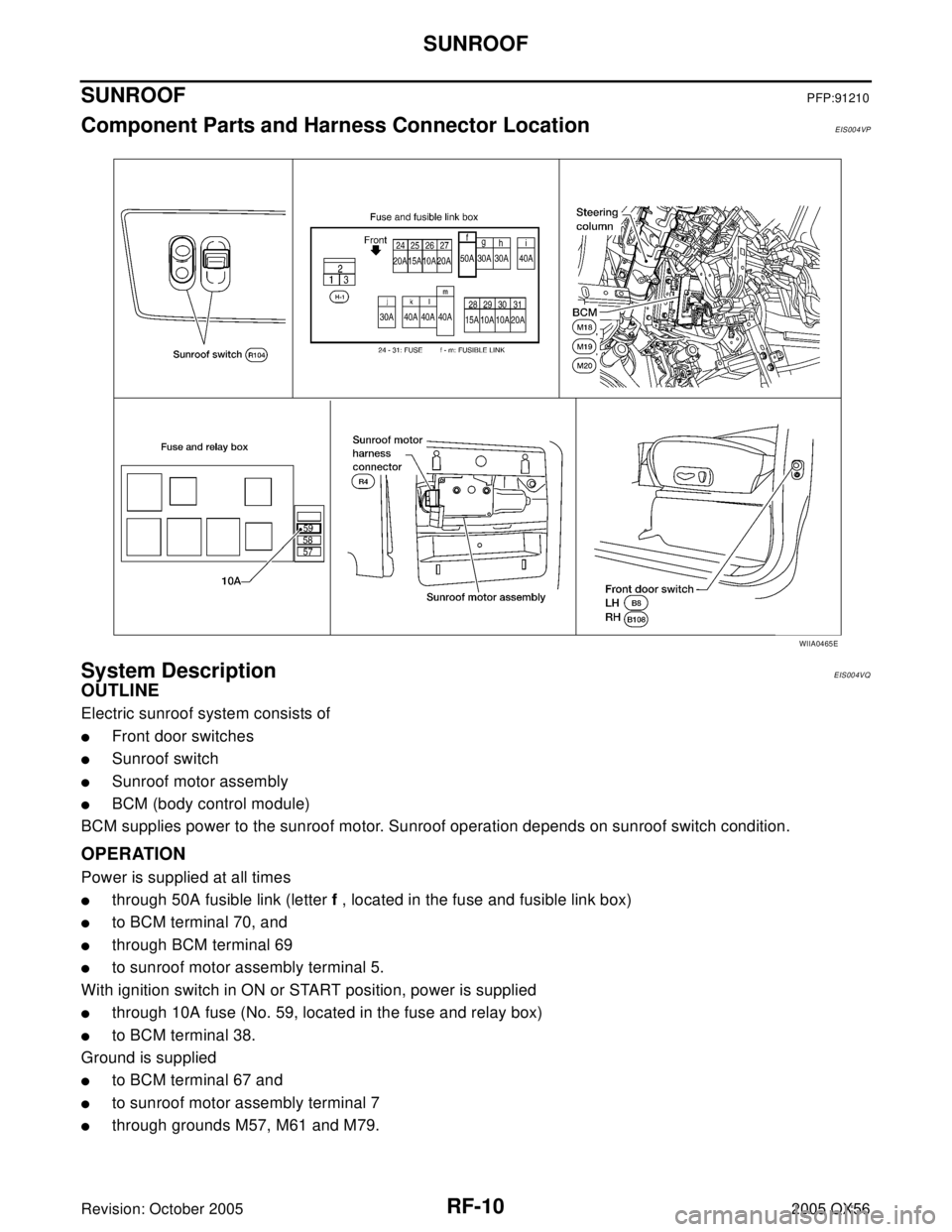
SUNROOFPFP:91210
Component Parts and Harness Connector LocationEIS004VP
System DescriptionEIS004VQ
OUTLINE
Electric sunroof system consists of
�Front door switches
�Sunroof switch
�Sunroof motor assembly
�BCM (body control module)
BCM supplies power to the sunroof motor. Sunroof operation depends on sunroof switch condition.
OPERATION
Power is supplied at all times
�through 50A fusible link (letter f , located in the fuse and fusible link box)
�to BCM terminal 70, and
�through BCM terminal 69
�to sunroof motor assembly terminal 5.
With ignition switch in ON or START position, power is supplied
�through 10A fuse (No. 59, located in the fuse and relay box)
�to BCM terminal 38.
Ground is supplied
�to BCM terminal 67 and
�to sunroof motor assembly terminal 7
�through grounds M57, M61 and M79.
WIIA0465E
Page 2835 of 3419

RF-18
SUNROOF
Revision: October 20052005 QX56
BCM Power Supply and Ground Circuit CheckEIS004W1
1. CHECK FUSE
Check the following BCM fuse and fusible link.
NOTE:
Refer to RF-10, "
Component Parts and Harness Connector Location" .
OK or NG
OK >> GO TO 2.
NG >> If fuse is blown, be sure to eliminate cause of blown fuse before installing new fuse. Refer to PG-
4, "POWER SUPPLY ROUTING CIRCUIT" .
2. CHECK POWER SUPPLY CIRCUIT
1. Turn ignition switch OFF.
2. Disconnect BCM connectors.
3. Check voltage between BCM connectors M18 and M20 termi-
nals 38, 70 and ground.
OK or NG
OK >> GO TO 3.
NG >> Repair or replace harness.
3. CHECK GROUND CIRCUIT
Check continuity between BCM connector M20 terminal 67 and
ground.
OK or NG
OK >> Power supply and ground circuit is OK.
NG >> Repair or replace harness.
Retained power operation does not operate properly.1. Check the retained power operation mode settingRF-112. BCM power supply and ground circuit checkRF-18
3. Door switch checkRF-21
4. Replace sunroof motor assemblyRF-27
Motor does not stop at the sunroof fully-open or fully-
closed position.1. Initialization procedure checkRF-11
2. Replace sunroof motor assemblyRF-27
Sunroof does not do the interruption detection. 1. Replace sunroof motor assemblyRF-27
Symptom Diagnostic procedure and repair order Refer to page
Component Parts Terminal No. (SIGNAL) Ampere No. Location
BCM38 (IGN power supply) 10A 59 Fuse and relay box
70 (BAT power supply) 50A f Fuse and fusible link box
ConnectorTerminals
(Wire color)
ConditionVo l ta g e
(Approx.)
(+) (–)
M18 38 (W/L)
GroundIgnition switch ON
Battery voltage
M20 70 (W/B) Igniting switch OFF
WIIA0229E
Connector Terminals (Wire color) Continuity
M20 67 (B) Ground YES
LIIA0915E
Page 2898 of 3419

TROUBLE DIAGNOSES FOR SYMPTOMS
RSU-23
C
D
F
G
H
I
J
K
L
MA
B
RSU
Revision: October 20052005 QX56
TROUBLE DIAGNOSES FOR SYMPTOMSPFP:99999
Load Leveling Rear Air Suspension System Does Not OperateEES001HD
1. CHECK WARNING LAMP ACTIVATION
Make sure warning lamp remains off while driving.
OK or NG
OK >> GO TO 2.
NG >> Carry out self-diagnosis. Refer to RSU-14, "
SELF-DIAGNOSIS" .
2. CHECK FUSES
Check that the following fuses are not blown.
OK or NG
OK >> GO TO 3.
NG >> If fuse is blown, be sure to eliminate cause of blown fuse before installing new fuse. Refer to PG-
4, "POWER SUPPLY ROUTING CIRCUIT" .
3. CHECK SUSPENSION CONTROL UNIT POWER AND GROUND
1. Turn the ignition switch ON.
2. Check voltage between suspension control unit connector B3
terminal 6 (G/R) and ground and between suspension control
unit connector B3 terminal 7 (W/L) and ground.
3. Check resistance between suspension control unit connector B3
terminal 16 (B) and ground.
OK or NG
OK >> GO TO 4.
NG >> Repair the circuit.
Unit Terminals Signal name Fuse or Fusible Link
Suspension control unit6 Ignition switch ON or START 12 (10A)
7
Battery power29 (10A)
Compressor motor relay 5 g (30A)
Combination meter24 Ignition switch ON or START 14 (10A)
8 Battery power 19 (10A)
Voltage : Approx. 12V
WEIA0069E
Continuity should exist.
WEIA0070E
Page 2947 of 3419

SC-10
STARTING SYSTEM
Revision: October 20052005 QX56
STARTING SYSTEMPFP:23300
System DescriptionEKS00B7B
Power is supplied at all times:
�through 40A fusible link (letter m , located in the fuse and fusible link box)
�to ignition switch terminal B.
With the ignition switch in the START position, power is supplied:
�from ignition switch terminal ST
�to IPDM E/R terminal 21.
With the ignition switch in the ON or START position, power is supplied to IPDM E/R (intelligent power distribu-
tion module engine room) CPU.
With the selector lever in the P or N position, power is supplied:
�through A/T assembly terminal 9
�to IPDM E/R terminal 48.
Ground is supplied at all times:
�to IPDM E/R terminals 38 and 59
�through body grounds E9, E15 and E24.
Then the starter relay is turned on.
The IPDM E/R is energized and power is supplied:
�from terminal 19 of the IPDM E/R
�to terminal 1 of the starter motor windings.
The starter motor plunger closes and provides a closed circuit between the battery and the starter motor. The
starter motor is grounded to the cylinder block. With power and ground supplied, the starter motor operates.

Revision: October 20052005 QX56
FUSE BLOCK-JUNCTION BOX(J/B)PFP:24350
Terminal ArrangementEKS00BNN
WKIA2016E")