Page 4298 of 4731

POWER STEERING GEAR AND LINKAGE PS-23
C
D E
F
H I
J
K L
M A
B
PS
Revision: 2005 July 2005 FX
CAUTION:
�Secure steering gear assembly with a vise, using copper
plates or something similar to prevent it from being dam-
aged. Do not grip cylinder with a vise.
�Before performing disassembly, clean steering gear assem-
bly with kerosene. Be careful not to bring any kerosene into
contact with the discharge and return port connectors.
DISASSEMBLY
1. Remove cylinder tubes from gear housing assembly.
2. Remove rear cover cap from gear housing assembly.
3. Measure adjusting screw height from gear housing assembly, then loosen adjusting screw.
CAUTION:
�Do not turn adjusting screw more than twice.
�Replace steering gear assembly when adjusting screw is
removed or more than twice.
4. Use a rear cover wrench (SST) to remove rear cover from sub- gear assembly.
5. Remove O-ring with a flat-bladed screwdriver, and pull out rear cover.
6. Remove sub-gear assembly from gear housing assembly. CAUTION:
In order to protect oil seal from any damage, pull sub-gear
assembly out straightly.
7. Loosen lock nut of outer socket, and remove outer socket.
8. Remove boot clamps of the small diameter side and the large diameter side, then remove boot.
1. Cotter pin 2. Outer socket 3. Boot clamp
4. Boot 5. Inner socket 6. Boot clamp
7. Gear housing assembly 8. Cylinder tubes 9. Rear cover cap
10. Rear cover 11. O-ring 12. Sub-gear assembly
13. Rack oil seal 14. Rack assembly 15. Rack Teflon ring
16. O-ring 17. End cover assembly
SGIA0544E
SGIA0568E
SGIA0728E
SGIA0508E
Page 4303 of 4731
, install rear cover to gear housing assembly.
10. Confirm projection on rear cover cap nearly fit wi")
PS-28
POWER STEERING GEAR AND LINKAGE
Revision: 2005 July 2005 FX
9. Use a rear cover wrench (SST), install rear cover to gear housing assembly.
10. Confirm projection on rear cover cap nearly fit with marking position on gear housing assembly.
11 . A p p l y t h r e a d l o c k i n g a d h e s i v e ( T h r e e B o u n d T B 1111 B o r e q u i v - alent. Refer to GI-48
) to the thread of adjusting screw to the
adjusting screw height from gear housing assembly. The adjust-
ing screw height is the same as it was measured in the overhaul
in advance.
12. Rotate pinion ten times whole range of rack so that parts get to fit with each other.
13. Measure pinion rotating torque within from –180 ° to +180 °,
make preload gauge (SST) and torque adapter (SST) in rack
neutral position, then hold preload gauge (SST) at maximum
torque.
14. After loosening adjusting screw once, tighten it again with torque of 5.4 N·m (0.55 kg-m, 48 in-lb). After that loosen it within 20 ° to
40 °.
15. Measure pinion rotating torque with torque adapter (SST) and preload gauge (SST), then confirm whether it's reading is within
the specified value. If the reading is not within the specified
value, readjust screw angle with adjusting screw. Change gear
assembly to new one, if the reading is still not within the speci-
fied value or the rotating torque of adjusting screw is less than 5
N·m (0.51 kg-m, 44 in-lb).
16. Turn pinion fully to the end of the left with inner socket to gear housing assembly.
17. Set dial gauge to rack as shown in the figure. Measure vertical movement of rack when pinion is turned counterclockwise with
torque of 19.6 N·m (2.0 kg-m, 14 ft-lb). Check reading is within
the specified value. If reading is outside of the specification,
readjust screw angle with adjusting screw. If reading is still out-
side of specification, or if the rotating torque of adjusting screw is
less than 5 N·m (0.51 kg-m, 44 in-lb), replace steering gear
assembly.
SGIA0568E
SGIA0483E
Pinion rotating torque:
Around neutral position (within ±100 °)
Average “A”:
0.8 − 2.0 N·m (0.08 − 0.20 kg-m, 7 − 18 in-lb)
Other than above (more than ±100 °)
Maximum variation “B”:
2.3 N·m (0.23 kg-m, 20 in-lb)
SGIA0160E
SGIA0484E
Page 4304 of 4731

POWER STEERING GEAR AND LINKAGE PS-29
C
D E
F
H I
J
K L
M A
B
PS
Revision: 2005 July 2005 FX
18. Install large-diameter side of boot to gear housing assembly.
19. Install small-diameter side of boot to the mounting groove of inner socket boot.
20. Install boot clamp to the small-diameter side of boot.
21. Install boot clamp to the large-diameter side of boot.
NOTE:
Do not reuse boot clamp.
a. Tighten large-diameter side of RH/LH boot with boot clamp (stainless wire).
b. After wrapping clamp around boot groove for two turns, insert screwdriver in loop on both ends of wire. Twist 4 to 4.5 turns
while pulling with a force of approx. 98 N (10 kg, 22 lb).
c. Twist boot clamp as shown in the figure, pay attention to rela- tionship between winding and twisting directions.
22. Install cylinder tubes to gear housing assembly.
23. Install lock nut and outer socket to inner socket. Amount of vertical movement with rack Less than 0.265 mm (0.01 in)
Measuring point Axial direction of rack 5 mm (0.2 in) away from
end of gear housing
Radius direction of rack Shaft direction of adjust- ing screw
SGIA0550E
Wire length “L” : 390 mm (15.35 in)
SGIA0163E
SGIA0164E
SGIA0544E
Page 4305 of 4731
PS-30
POWER STEERING GEAR AND LINKAGE
Revision: 2005 July 2005 FX
24. Tighten lightly inner socket in specified length “L”, then tighten
lock nut at specified torque. Refer to PS-22, "
Disassembly and
Assembly" . Reconfirm if inner socket length is within limit of
specified length “L”.
CAUTION:
Perform toe-in adjustment after this procedure. Length
achieved after toe-in adjustment is not necessary value
given here. Inner socket length “L” : 135.2 mm (5.32 in)
SGIA0167E
Page 4312 of 4731
AGS000H4
INSPECTION BEFORE DISASSEMBLY
Disassemble power steer")
POWER STEERING OIL PUMP PS-37
C
D E
F
H I
J
K L
M A
B
PS
Revision: 2005 July 2005 FX
Disassembly and Assembly (VK45DE Models)AGS000H4
INSPECTION BEFORE DISASSEMBLY
Disassemble power steering oil pump only if the following items are found.
�Oil leakage from oil pump.
�Deformed or damaged pulley
�Poor performance
DISASSEMBLY
NOTE:
Fix oil pump in vise as the occasion demands.
CAUTION:
When retaining drive shaft in a vise, always use copper or aluminum plates between vise and shaft.
1. Unscrew three bracket bolts and remove bracket from rear cover.
2. Unscrew four rear cover bolts and remove rear cover from body assembly.
3. Remove gasket from body assembly.
4. Remove lock pin, cartridge and side plate from body assembly.
5. Remove pulley from drive shaft assembly.
1. Bracket 2. Rear cover 3. Gasket
4. Lock pin 5. Cam ring 6. Rotor
7. Vane 8. Cartridge 9. Side plate
10. O-ring 11. Body assembly 12. Oil seal
13. Drive shaft assembly 14. Snap ring 15. Pulley
16. Spring washer 17. Spring 18. Flow control valve
19. O-ring 20. Connector bolt 21. Joint
22. Washer 23. Suction pipe 24. O-ring
SGIA0523E
Page 4313 of 4731

PS-38
POWER STEERING OIL PUMP
Revision: 2005 July 2005 FX
6. Remove snap ring from drive shaft assembly and press out it.
CAUTION:
When removing snap ring, be careful not to damage drive
shaft assembly.
7. Using a screwdriver, remove oil seal for body assembly.
8. Remove O-ring from body assembly.
9. Loosen lock nut and remove washer, O-ring, joint then remove connector bolt, O-ring and pull out flow control valve and spring
from body assembly.
CAUTION:
Be careful not to drop and deform the flow control valve.
10. Remove suction pipe from body assembly.
11. Remove O-ring for suction pipe.
INSPECTION AFTER DISASSEMBLY
Body Assembly and Rear Cover Inspection
Check body assembly and the inside of rear cover for damage. If any damage is found, replace with new part
for rear cover and replace with new power steering pump assembly for body assembly.
Cartridge Assembly Inspection
Check cam ring, side plate, rotor and vane for damage. If any damage is found, replace cartridge assembly
with new one.
ASSEMBLY
NOTE:
Fix oil pump in vise as vise occasion demands.
CAUTION:
When retaining drive shaft assembly in a vise, always use copper or aluminum plates between vise
and shaft.
SST010B
SST034A
SGIA0524E
Page 4314 of 4731

POWER STEERING OIL PUMP PS-39
C
D E
F
H I
J
K L
M A
B
PS
Revision: 2005 July 2005 FX
1. Apply a coat of Genuine Nissan PSF or equivalent to oil seal lip
and to the circumference of oil seal. Using proper tool, such as
hand press machine, install it to body assembly.
NOTE:
Do not reuse oil seal.
2. Apply a coat of Genuine Nissan PSF or equivalent to drive shaft assembly and press drive shaft assembly into body assembly
with suitable tool, then install snap ring.
NOTE:
Do not reuse snap ring.
3. Apply a coat of Genuine Nissan PSF or equivalent to O-ring and Install O-ring into body assembly.
NOTE:
Do not reuse O-ring.
4. Install side plate to body assembly.
5. Install lock pin into lock pin hole, and install cam-ring as shown in the figure.
�When installing cam-ring, turn carved face with a letter (E) of
it to rear cover.
CAUTION:
Do not confuse the assembling direction of cam ring. If
cam ring is installed facing the incorrect direction, it may
cause pump operation malfunction.
6. Install rotor to body assembly.
SST038A
SGIA0422E
SGIA0591E
Page 4315 of 4731
PS-40
POWER STEERING OIL PUMP
Revision: 2005 July 2005 FX
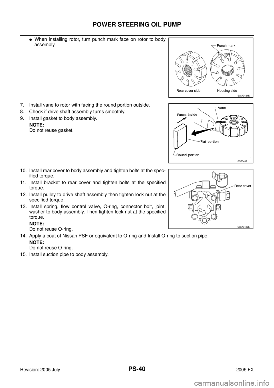
�When installing rotor, turn punch mark face on rotor to body
assembly.
7. Install vane to rotor with facing the round portion outside.
8. Check if drive shaft assembly turns smoothly.
9. Install gasket to body assembly. NOTE:
Do not reuse gasket.
10. Install rear cover to body assembly and tighten bolts at the spec- ified torque.
11. Install bracket to rear cover and tighten bolts at the specified torque.
12. Install pulley to drive shaft assembly then tighten lock nut at the specified torque.
13. Install spring, flow control valve, O-ring, connector bolt, joint, washer to body assembly. Then tighten lock nut at the specified
torque.
NOTE:
Do not reuse O-ring.
14. Apply a coat of Nissan PSF or equivalent to O-ring and Install O-ring to suction pipe. NOTE:
Do not reuse O-ring.
15. Install suction pipe to body assembly.
SGIA0424E
SST843A
SGIA0425E