Page 4246 of 4731

HARNESS PG-69
C
D E
F
G H
I
J
L
M A
B
PG
Revision: 2005 July 2005 FX
P/SCKT WW Power Socket
PGC/V EC EVAP Canister Purge Volume Control Solenoid Valve
PHASE EC Camshaft Position Sensor (PHASE)
PHSB1 EC Camshaft Position Sensor (PHASE) (Bank 1)
PHSB2 EC Camshaft Position Sensor (PHASE) (Bank 2)
PNP/SW AT Park/Neutral Position Switch
PNP/SW EC Park/Neutral Position Switch
POS EC Crankshaft Position Sensor (CKPS) (POS)
POWER PG Power Supply Routing
PRE/SE EC EVAP Control System Pressure Sensor
PS/SEN EC Power Steering Pressure Sensor
R/VIEW DI Rear View Camera Control System
ROOM/L LT Interior Room Lamp
RP/SEN EC Refrigerant Pressure Sensor
SEAT SE Power Seat
SEN/PW EC Sensor Power Supply
SHIFT AT A/T Shift Lock System
SNOWSW EC Snow Mode Switch
SROOF RF Sunroof
SRS SRS Supplemental Restraint System
START SC Starting System
STOP/L LT Stop Lamp
STSIG AT Start Signal Circuit
T/WARN WT Low Tire Pressure Warning System
TAIL/L LT Parking, License and Tail Lamps
TPS1 EC Throttle Position Sensor (Sensor 1)
TPS2 EC Throttle Position Sensor (Sensor 2)
TPS3 EC Throttle Position Sensor
TRNSCV BL Homelink Universal Transceiver
TURN LT Turn Signal and Hazard Warning Lamp
VDC BRC Vehicle Dynamics Control System
VEHSEC BL Vehicle Security System
VENT/V EC EVAP Canister Vent Control Valve
VIAS/V EC VIAS Control Solenoid Valve
VSSA/T AT Vehicle Speed Sensor A/T (Revolution Sensor)
WARN DI Warning Lamps
WINDOW GW Power Window
WIP/R WW Rear Wiper and Washer
WIPER WW Front Wiper and Washer Code Section Wiring Diagram Name
Page 4251 of 4731
PG-74
HARNESS CONNECTOR
Revision: 2005 July 2005 FX
HARNESS CONNECTOR PFP:00011
DescriptionAKS007W3
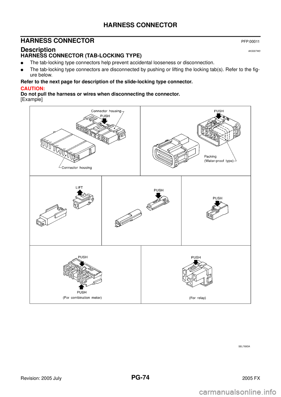
HARNESS CONNECTOR (TAB-LOCKING TYPE)
�The tab-locking type connectors help prevent accidental looseness or disconnection.
�The tab-locking type connectors are disconnected by pushing or lifting the locking tab(s). Refer to the fig-
ure below.
Refer to the next page for description of the slide-locking type connector.
CAUTION:
Do not pull the harness or wires when disconnecting the connector.
[Example]
SEL769DA
Page 4252 of 4731
HARNESS CONNECTOR PG-75
C
D E
F
G H
I
J
L
M A
B
PG
Revision: 2005 July 2005 FX
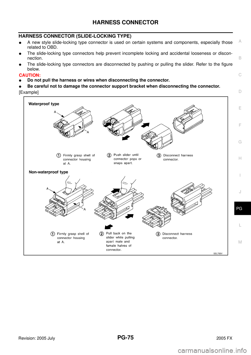
HARNESS CONNECTOR (SLIDE-LOCKING TYPE)
�A new style slide-locking type connector is used on certain systems and components, especially those
related to OBD.
�The slide-locking type connectors help prevent incomplete locking and accidental looseness or discon-
nection.
�The slide-locking type connectors are disconnected by pushing or pulling the slider. Refer to the figure
below.
CAUTION:
�Do not pull the harness or wires when disconnecting the connector.
�Be careful not to damage the connector support bracket when disconnecting the connector.
[Example]
SEL769V
Page 4259 of 4731
PG-82
FUSE BLOCK - JUNCTION BOX (J/B)
Revision: 2005 July 2005 FX
FUSE BLOCK - JUNCTION BOX (J/B)PFP:24350
Terminal ArrangementAKS007W8
CKIM0222E
Page 4263 of 4731
PR-2
PREPARATION
Revision: 2005 July 2005 FX
PREPARATIONPFP:00002
Special Service ToolsADS001A4
The actual shapes of Kent-Moore tools may differ from those of special service tools illustrated here.
Commercial Service ToolsADS001A5
Tool number
(Kent-Moore No.)
Tool name Description
KV40104000
(—)
Flange wrench
a: 85 mm (3.35 in)
b: 65 mm (2.56 in) Removing and installing center flange lock nut
ST30031000
(J-22912-01)
Puller
a: 90 mm (3.54 in) dia.
b: 50 mm (1.97 in) dia. Removing rear propeller shaft center bearing
NT659
NT411
Tool name
Description
Power tool Loosening bolts and nuts
PBIC0190E
Page 4269 of 4731
PR-8
REAR PROPELLER SHAFT
Revision: 2005 July 2005 FX
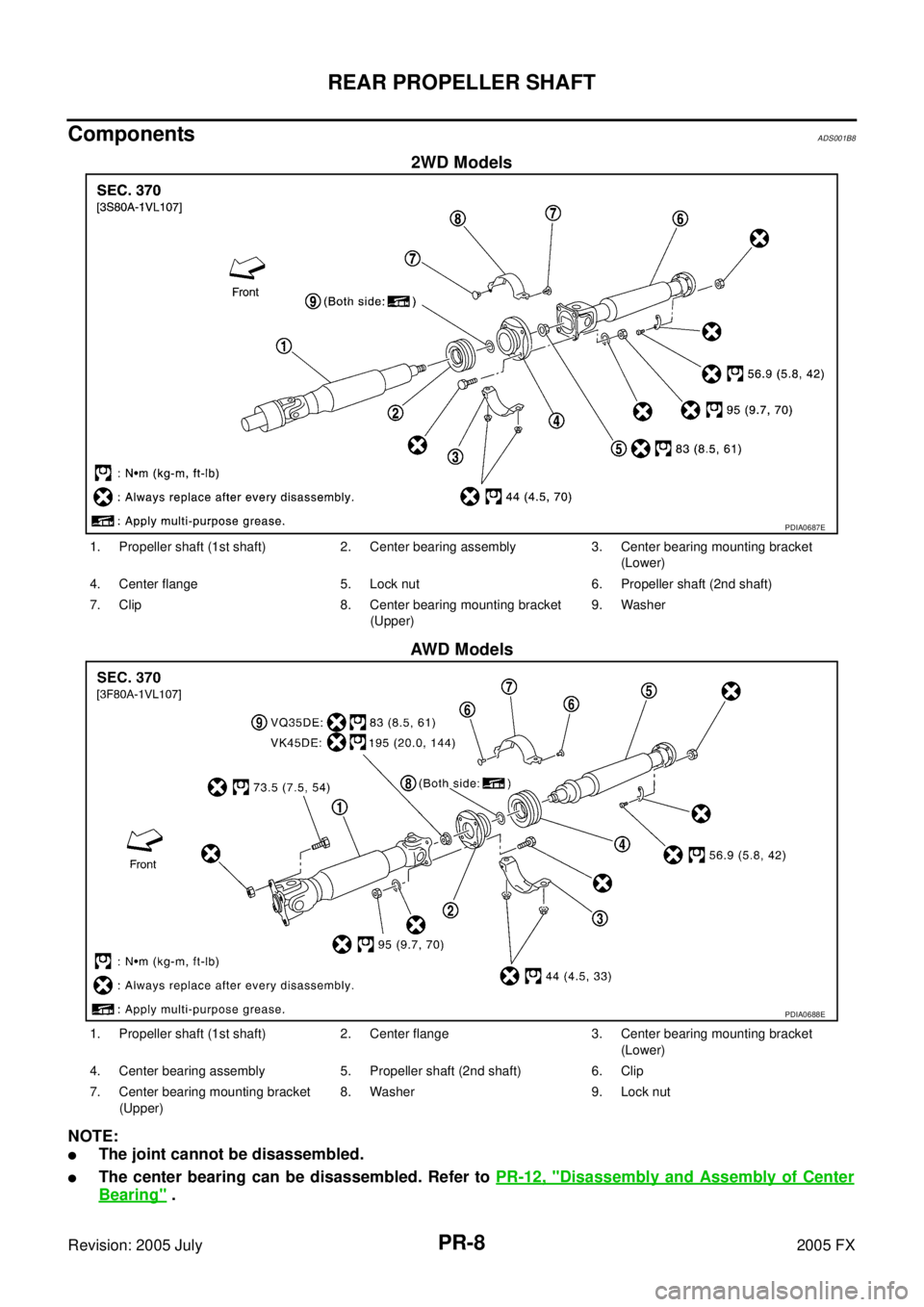
ComponentsADS001B8
2WD Models
AWD Models
NOTE:
�The joint cannot be disassembled.
�The center bearing can be disassembled. Refer to PR-12, "Disassembly and Assembly of Center
Bearing" .
PDIA0687E
1. Propeller shaft (1st shaft) 2. Center bearing assembly 3. Center bearing mounting bracket
(Lower)
4. Center flange 5. Lock nut 6. Propeller shaft (2nd shaft)
7. Clip 8. Center bearing mounting bracket (Upper) 9. Washer
PDIA0688E
1. Propeller shaft (1st shaft) 2. Center flange 3. Center bearing mounting bracket
(Lower)
4. Center bearing assembly 5. Propeller shaft (2nd shaft) 6. Clip
7. Center bearing mounting bracket (Upper) 8. Washer 9. Lock nut
Page 4273 of 4731
PR-12
REAR PROPELLER SHAFT
Revision: 2005 July 2005 FX
Disassembly and Assembly of Center BearingADS001AD
DISASSEMBLY
1. Put matching marks on propeller shaft and center flange, then
disassemble the 1st and 2nd propeller shaft.
CAUTION:
For matching mark, use paint. Do not damage the propeller
shaft flange and center flange.
2. Put matching marks onto the center flange and propeller shaft end as shown.
CAUTION:
For matching mark, use paint. Do not damage propeller
shaft end and center flange.
3. Hold the center flange using the flange wrench, and remove the lock nut.
4. Remove the center flange using a commercial available bearing puller then remove washer.
5. Press out the center bearing using the puller and hydraulic press.
SDIA1538E
SDIA1539E
Tool number : KV40104000 ( — )
SDIA1540E
Tool number : ST30031000 (J-22912-01)
SDIA1541E
Page 4274 of 4731
 and 3F80A-1VL107
(VK45DE/AWD) type
�Install the center beari")
REAR PROPELLER SHAFT PR-13
C E F
G H
I
J
K L
M A
B
PR
Revision: 2005 July 2005 FX
ASSEMBLY
1.For the 3S80A-1VL107 (VQ35DE/2WD) and 3F80A-1VL107
(VK45DE/AWD) type
�Install the center bearing with its “F” mark facing the front of
the vehicle.
For the 3F80A-1VL107(VQ35DE/AWD) type
�Install the center bearing with its “F” mark facing the rear of
the vehicle.
2. Apply multi-purpose grease to the each face of the washer, then install washer.
3. Install the center flange onto the propeller shaft with aligning the marks that are marked while removal.
4. Install and tighten the lock nut to specified torque. Refer to PR-8, "
Components" .
CAUTION:
Do not use the lock nut.
5. Place a piece of wood under the center flange, stake the lock nut against the propeller shaft groove. [For the 3S80A-1VL107
(VQ35DE/2WD) and 3F80A-1VL107 (VQ35DE/AWD) type]
6. Assemble the 1st and 2nd shaft propeller shafts while aligning the matching marks that are marked during removal.
7. Install and tighten the bolts/nuts and tighten them to specified torque. Refer to PR-8, "
Components" .
CAUTION:
Do not reuse the bolts, nuts and washers.
SDIA1542E
SDIA1543E
SDIA1538E

Revision: 2005 July 2005 FX
FUSE BLOCK - JUNCTION BOX (J/B)PFP:24350
Terminal ArrangementAKS007W8
CKIM0222E")