Page 4357 of 4731

RF-18
SUNROOF
Revision: 2005 July 2005 FX
Trouble Diagnosis Chart by SymptomAIS003D0
Power Supply and Ground Circuit Check of BCMAIS003D1
1. CHECK FUSE
�Check 15A fuse [No.1, located in the fuse block (J/B)]
�Check 15A fuse [No.22, located in the fuse block (J/B)]
�Check 50A fusible link (letter M, located in the fuse and fusible link box).
NOTE:
Refer to RF-10, "
Component Parts and Harness Connector Location" .
OK or NG
OK >> GO TO 2.
NG >> If fuse is blown out, be sure to eliminate cause of malfunction before installing new fuse. Refer to RF-10, "
Component Parts and Harness Connector Location" .
2. CHECK POWER SUPPLY CIRCUIT
1. Turn ignition switch ON.
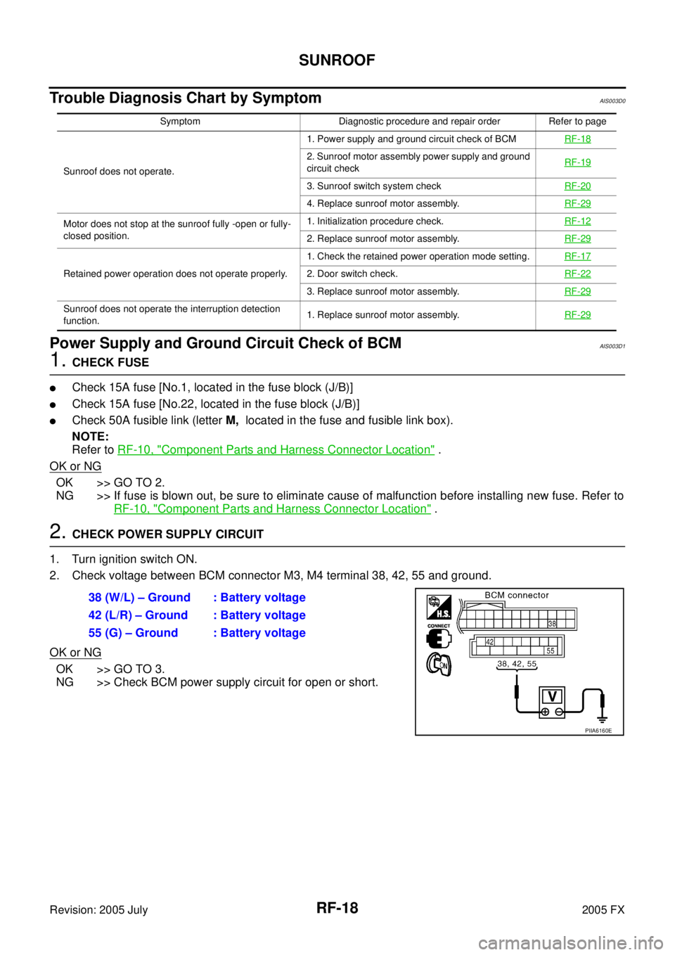
2. Check voltage between BCM connector M3, M4 terminal 38, 42, 55 and ground.
OK or NG
OK >> GO TO 3.
NG >> Check BCM power supply circuit for open or short.
Symptom Diagnostic procedure and repair order Refer to page
Sunroof does not operate. 1. Power supply and ground circuit check of BCM
RF-18
2. Sunroof motor assembly power supply and ground
circuit check RF-19
3. Sunroof switch system check
RF-20
4. Replace sunroof motor assembly.RF-29
Motor does not stop at the sunroof fully -open or fully-
closed position. 1. Initialization procedure check.
RF-12
2. Replace sunroof motor assembly.RF-29
Retained power operation does not operate properly. 1. Check the retained power operation mode setting.
RF-172. Door switch check.RF-22
3. Replace sunroof motor assembly.RF-29
Sunroof does not operate the interruption detection
function. 1. Replace sunroof motor assembly.
RF-29
38 (W/L) – Ground : Battery voltage
42 (L/R) – Ground : Battery voltage
55 (G) – Ground : Battery voltage
PIIA6160E
Page 4451 of 4731

SC-16
STARTING SYSTEM
Revision: 2005 July 2005 FX
DIAGNOSTIC PROCEDURE 2
Check “S” Connector Circuit
1. CHECK POWER SUPPLY FOR STARTER MOTOR “S” TERMINAL
1. Remove fuel pump fuse.
2. Crank or start the engine (where possible) until the fuel pressure is released.
3. Turn ignition switch OFF.
4. Disconnect starter motor connector.
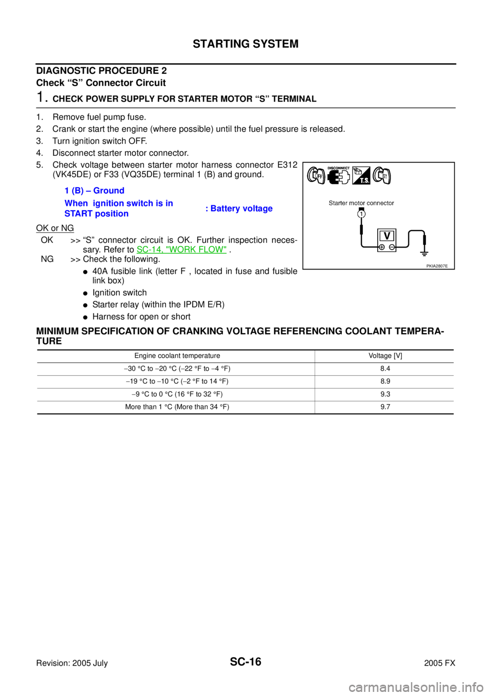
5. Check voltage between starter motor harness connector E312 (VK45DE) or F33 (VQ35DE) terminal 1 (B) and ground.
OK or NG
OK >> “S” connector circuit is OK. Further inspection neces- sary. Refer to SC-14, "
WORK FLOW" .
NG >> Check the following.
�40A fusible link (letter F , located in fuse and fusible
link box)
�Ignition switch
�Starter relay (within the IPDM E/R)
�Harness for open or short
MINIMUM SPECIFICATION OF CRANKING VOLTAGE REFERENCING COOLANT TEMPERA-
TURE
1 (B) – Ground
When ignition switch is in
START position : Battery voltage
PKIA2807E
Engine coolant temperature Voltage [V]
− 30 °C to −20 °C ( −22 °F to −4 °F) 8.4
− 19 °C to −10 °C ( −2 °F to 14 °F) 8.9
− 9 °C to 0 °C (16 °F to 32 °F) 9.3
More than 1 °C (More than 34 °F) 9.7
Page 4509 of 4731

SE-36
AUTOMATIC DRIVE POSITIONER
Revision: 2005 July 2005 FX
CHECK POWER SUPPLY AND GROUND
1. CHECK FUSE
Check if any of the following fuses in the BCM are blown.
�Check 50A fusible link (letter M , located in the fuse and fusible link box.)
�Check 15A fuse [No.22, located in the fuse block (J/B)]
�Check 10A fuse [No.1, located in the fuse block (J/B)]
�Check 10A fuse [No.6, located in the fuse block (J/B)]
NOTE:
Refer to SE-15, "
Component Parts and Harness Connector Location" .
OK or NG
OK >> GO TO 2.
NG >> If fuse is blown out, be sure to eliminate cause of malfunction before installing new fuse. Refer to
SE-15, "
Component Parts and Harness Connector Location" .
2. CHECK POWER SUPPLY CIRCUIT (BCM)
1. Turn ignition switch OFF.
2. Disconnect BCM connector.
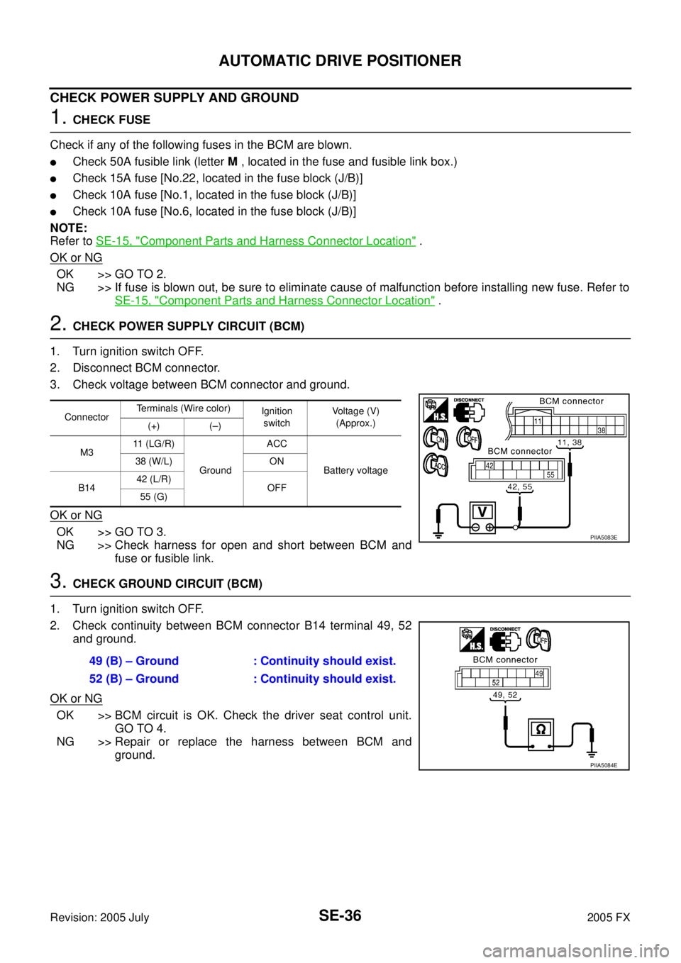
3. Check voltage between BCM connector and ground.
OK or NG
OK >> GO TO 3.
NG >> Check harness for open and short between BCM and fuse or fusible link.
3. CHECK GROUND CIRCUIT (BCM)
1. Turn ignition switch OFF.
2. Check continuity between BCM connector B14 terminal 49, 52 and ground.
OK or NG
OK >> BCM circuit is OK. Check the driver seat control unit. GO TO 4.
NG >> Repair or replace the harness between BCM and ground.
Connector Terminals (Wire color)
Ignition
switch Voltage (V)
(Approx.)
(+) (–)
M3 11 (LG/R)
Ground ACC
Battery voltage
38 (W/L) ON
B14 42 (L/R)
OFF
55 (G)
PIIA5083E
49 (B) – Ground : Continuity should exist.
52 (B) – Ground : Continuity should exist.
PIIA5084E