Page 2491 of 4731
![INFINITI FX35 2005 Service Manual EC-1098
[VK45DE]
DTC P0453 EVAP CONTROL SYSTEM PRESSURE SENSOR
Revision: 2005 July 2005 FX
10. CHECK EVAP CANISTER VENT CONTROL VALVE
Refer to EC-1081, "
Component Inspection" .
OK or NG
OK >> GO](/manual-img/42/57020/w960_57020-2490.png "INFINITI FX35 2005 Service Manual EC-1098
[VK45DE]
DTC P0453 EVAP CONTROL SYSTEM PRESSURE SENSOR
Revision: 2005 July 2005 FX
10. CHECK EVAP CANISTER VENT CONTROL VALVE
Refer to EC-1081, \"
Component Inspection\" .
OK or NG
OK >> GO")
EC-1098
[VK45DE]
DTC P0453 EVAP CONTROL SYSTEM PRESSURE SENSOR
Revision: 2005 July 2005 FX
10. CHECK EVAP CANISTER VENT CONTROL VALVE
Refer to EC-1081, "
Component Inspection" .
OK or NG
OK >> GO TO 11.
NG >> Replace EVAP canister vent control valve.
11 . CHECK EVAP CONTROL SYSTEM PRESSURE SENSOR
Refer to EC-1099, "
Component Inspection" .
OK or NG
OK >> GO TO 12.
NG >> Replace EVAP control system pressure sensor.
12. CHECK IF EVAP CANISTER SATURATED WITH WATER
1. Remove EVAP canister with EVAP canister vent control valve and EVAP control system pressure sensor attached.
2. Check if water will drain from the EVAP canister.
Ye s o r N o
Yes >> GO TO 13.
No >> GO TO 15.
13. CHECK EVAP CANISTER
Weigh the EVAP canister with the EVAP canister vent control valve and EVAP control system pressure sensor
attached.
The weight should be less than 2.1 kg (4.6 lb).
OK or NG
OK >> GO TO 15.
NG >> GO TO 14.
14. DETECT MALFUNCTIONING PART
Check the following.
�EVAP canister for damage
�EVAP hose between EVAP canister and vehicle frame for clogging or poor connection
>> Repair hose or replace EVAP canister.
15. CHECK INTERMITTENT INCIDENT
Refer to EC-854, "
TROUBLE DIAGNOSIS FOR INTERMITTENT INCIDENT" .
>> INSPECTION END
PBIB1031E
Page 2507 of 4731
![INFINITI FX35 2005 Service Manual EC-1114
[VK45DE]
DTC P0456 EVAP CONTROL SYSTEM
Revision: 2005 July 2005 FX
9. CHECK IF EVAP CANISTER SATURATED WITH WATER
1. Remove EVAP canister with EVAP canister vent control valve and EVAP contro](/manual-img/42/57020/w960_57020-2506.png "INFINITI FX35 2005 Service Manual EC-1114
[VK45DE]
DTC P0456 EVAP CONTROL SYSTEM
Revision: 2005 July 2005 FX
9. CHECK IF EVAP CANISTER SATURATED WITH WATER
1. Remove EVAP canister with EVAP canister vent control valve and EVAP contro")
EC-1114
[VK45DE]
DTC P0456 EVAP CONTROL SYSTEM
Revision: 2005 July 2005 FX
9. CHECK IF EVAP CANISTER SATURATED WITH WATER
1. Remove EVAP canister with EVAP canister vent control valve and EVAP control system pressure sensor attached.
2. Does water drain from the EVAP canister?
Ye s o r N o
Yes >> GO TO 10.
No (With CONSULT-II)>>GO TO 12.
No (Without CONSULT-II)>>GO TO 13.
10. CHECK EVAP CANISTER
Weigh the EVAP canister with the EVAP canister vent control valve and EVAP control system pressure sensor
attached.
The weight should be less than 2.1 kg (4.6 lb).
OK or NG
OK (With CONSULT-II)>>GO TO 12.
OK (Without CONSULT-II)>>GO TO 13.
NG >> GO TO 11.
11 . DETECT MALFUNCTIONING PART
Check the following.
�EVAP canister for damage
�EVAP hose between EVAP canister and vehicle frame for clogging or poor connection
>> Repair hose or replace EVAP canister.
12. CHECK EVAP CANISTER PURGE VOLUME CONTROL SOLENOID VALVE OPERATION
With CONSULT-II
1. Disconnect vacuum hose to EVAP canister purge volume control solenoid valve at EVAP service port.
2. Start engine.
3. Perform “PURG VOL CONT/V” in “ACTIVE TEST” mode.
4. Touch “Qu” on CONSULT-II screen to increase “PURG VOL CONT/V” opening to 100%.
5. Check vacuum hose for vacuum when revving engine up to 2,000 rpm.
OK or NG
OK >> GO TO 15.
NG >> GO TO 14.
PBIB1031E
PBIB0147E
Page 2632 of 4731
DTC P1444 EVAP CANISTER PURGE VOLUME CONTROL SOLENOID VALVE EC-1239
[VK45DE]
C
D E
F
G H
I
J
K L
M A
EC
Revision: 2005 July 2005 FX
10. CHECK IF EVAP CANISTER SATURATED WITH WATER
1. Remove EVAP canister with EVAP canister vent control valve and EVAP control system pressure sensor attached.
2. Check if water will drain from the EVAP canister.
Ye s o r N o
Ye s > > G O T O 11 .
No >> GO TO 13.
11 . CHECK EVAP CANISTER
Weigh the EVAP canister with the EVAP canister vent control valve and EVAP control system pressure sensor
attached.
The weight should be less than 2.1 kg (4.6 lb).
OK or NG
OK >> GO TO 13.
NG >> GO TO 12.
12. DETECT MALFUNCTIONING PART
Check the following.
�EVAP canister for damage
�EVAP hose between EVAP canister and vehicle frame for clogging or poor connection
>> Repair hose or replace EVAP canister.
13. CHECK INTERMITTENT INCIDENT
Refer to EC-854, "
TROUBLE DIAGNOSIS FOR INTERMITTENT INCIDENT" .
>> INSPECTION END
PBIB1031E
Page 2638 of 4731
![INFINITI FX35 2005 Service Manual DTC P1446 EVAP CANISTER VENT CONTROL VALVE EC-1245
[VK45DE]
C
D E
F
G H
I
J
K L
M A
EC
Revision: 2005 July 2005 FX
4. CHECK EVAP CANISTER
Weigh the EVAP canister with the EVAP canister v](/manual-img/42/57020/w960_57020-2637.png "INFINITI FX35 2005 Service Manual DTC P1446 EVAP CANISTER VENT CONTROL VALVE EC-1245
[VK45DE]
C
D E
F
G H
I
J
K L
M A
EC
Revision: 2005 July 2005 FX
4. CHECK EVAP CANISTER
Weigh the EVAP canister with the EVAP canister v")
DTC P1446 EVAP CANISTER VENT CONTROL VALVE EC-1245
[VK45DE]
C
D E
F
G H
I
J
K L
M A
EC
Revision: 2005 July 2005 FX
4. CHECK EVAP CANISTER
Weigh the EVAP canister with the EVAP canister vent control valve and EVAP control system pressure sensor
attached.
The weight should be less than 2.1 kg (4.6 lb).
OK or NG
OK >> GO TO 6.
NG >> GO TO 5.
5. DETECT MALFUNCTIONING PART
Check the following.
�EVAP canister for damage
�EVAP hose between EVAP canister and vehicle frame for clogging or poor connection
>> Repair hose or replace EVAP canister.
6. CHECK EVAP CONTROL SYSTEM PRESSURE SENSOR CONNECTOR
1. Disconnect EVAP control system pressure sensor harness connector.
2. Check connectors for water.
OK or NG
OK >> GO TO 7.
NG >> Replace EVAP control system pressure sensor.
7. CHECK EVAP CONTROL SYSTEM PRESSURE SENSOR
Refer to EC-1091, "
Component Inspection" .
OK or NG
OK >> GO TO 8.
NG >> Replace EVAP control system pressure sensor.
8. CHECK INTERMITTENT INCIDENT
Refer to EC-854, "
TROUBLE DIAGNOSIS FOR INTERMITTENT INCIDENT" .
>> INSPECTION END
Component InspectionABS007TX
EVAP CANISTER VENT CONTROL VALVE
With CONSULT-II
1. Remove EVAP canister vent control valve from EVAP canister.
2. Check portion B of EVAP canister vent control valve for being
rusted.
If NG, replace EVAP canister vent control valve.
If OK, go to next step.
3. Reconnect harness connectors disconnected.
4. Turn ignition switch ON. Water should not exist.
PBIB1033E
Page 2959 of 4731
EM-124
[VQ35DE]
CYLINDER BLOCK
Revision: 2005 July 2005 FX
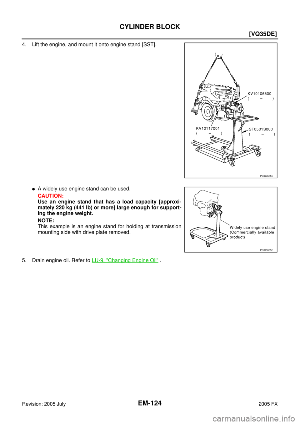
4. Lift the engine, and mount it onto engine stand [SST].
�A widely use engine stand can be used.
CAUTION:
Use an engine stand that has a load capacity [approxi-
mately 220 kg (441 lb) or more] large enough for support-
ing the engine weight.
NOTE:
This example is an engine stand for holding at transmission
mounting side with drive plate removed.
5. Drain engine oil. Refer to LU-9, "
Changing Engine Oil" .
PBIC2685E
PBIC0085E
Page 3038 of 4731
![INFINITI FX35 2005 Service Manual TIMING CHAIN EM-203
[VK45DE]
C
D E
F
G H
I
J
K L
M A
EM
Revision: 2005 July 2005 FX
a. Remove rear plate cover, and set ring gear stopper (SST).
b. Loosen crankshaft pulley bolt, and the](/manual-img/42/57020/w960_57020-3037.png "INFINITI FX35 2005 Service Manual TIMING CHAIN EM-203
[VK45DE]
C
D E
F
G H
I
J
K L
M A
EM
Revision: 2005 July 2005 FX
a. Remove rear plate cover, and set ring gear stopper (SST).
b. Loosen crankshaft pulley bolt, and the")
TIMING CHAIN EM-203
[VK45DE]
C
D E
F
G H
I
J
K L
M A
EM
Revision: 2005 July 2005 FX
a. Remove rear plate cover, and set ring gear stopper (SST).
b. Loosen crankshaft pulley bolt, and then pull crankshaft pulley with both hands to remove it.
CAUTION:
�Do not remove crankshaft pulley bolt. Keep loosened
crankshaft pulley bolt in place to protect removed crank-
shaft pulley from dropping.
�Do not remove balance weight (inner hexagon bolt) at the
front of crankshaft pulley.
9. Remove oil pan and oil strainer. Refer to EM-185, "
OIL PAN AND OIL STRAINER" .
10. Remove front cover as follows:
a. Loosen mounting bolts in reverse order as shown in the figure.
b . U s e s e a l c u t t e r [ S S T: K V 1 0 1111 0 0 ( J 3 7 2 2 8 ) ] t o c u t l i q u i d g a s k e t for removal.
CAUTION:
�Exercise care not to damage mating surfaces.
�After removal, handle front cover carefully so it does not
tilt, cant, or warp under a load.
11. Remove front oil seal from front cover using suitable tool.
�Use screwdriver for removal.
CAUTION:
Be careful not to damage front cover.
12. Remove O-rings from cylinder heads (right and left bank) and cylinder block.
13. Remove chain tensioner cover from front cover.
�U s e s e a l c u t t e r [ S S T: K V 1 0 1111 0 0 ( J 3 7 2 2 8 ) ] t o c u t l i q u i d g a s k e t f o r r e m o v e .
14. Remove oil pump drive spacer.
�Set bolts in the two bolt holes [M6 × pitch 1.0 mm (0.04 in)] on
front surface. Using suitable puller, pull oil pump drive spacer
off from crankshaft.
NOTE:
The dimension between the centers of the two bolt holes is 33
mm (1.30 in).
In the figure, a commercial steering puller is used.
15. Remove oil pump. Refer to LU-31, "
OIL PUMP" .
16. Remove chain tensioner (left bank) as follows:
PBIC1656E
KBIA0354J
SBIA0373E
PBIC2342E
Page 3061 of 4731
![INFINITI FX35 2005 Service Manual EM-226
[VK45DE]
OIL SEAL
Revision: 2005 July 2005 FX
Removal and Installation of Front Oil SealABS006IN
REMOVAL
1. Remove the following parts:
�Front engine undercover
�Radiator; Refer to CO-41, "RADI](/manual-img/42/57020/w960_57020-3060.png "INFINITI FX35 2005 Service Manual EM-226
[VK45DE]
OIL SEAL
Revision: 2005 July 2005 FX
Removal and Installation of Front Oil SealABS006IN
REMOVAL
1. Remove the following parts:
�Front engine undercover
�Radiator; Refer to CO-41, \"RADI")
EM-226
[VK45DE]
OIL SEAL
Revision: 2005 July 2005 FX
Removal and Installation of Front Oil SealABS006IN
REMOVAL
1. Remove the following parts:
�Front engine undercover
�Radiator; Refer to CO-41, "RADIATOR"
�Drive belt; Refer to EM-173, "DRIVE BELTS" .
�Cooling fan; Refer to CO-49, "COOLING FAN" .
�Rear plate cover; Refer to EM-185, "OIL PAN AND OIL STRAINER" .
2. Remove crankshaft pulley as follows:
a. Set ring gear stopper (SST).
b. Loosen crankshaft pulley bolt, and then pull crankshaft pulley with both hands to remove it.
CAUTION:
�Do not remove crankshaft pulley bolt. Keep loosened
crankshaft pulley bolt in place to protect removed crank-
shaft pulley from dropping.
�Do not remove balance weight (inner hexagon bolt) at the
front of crankshaft pulley.
3. Remove front oil seal using suitable tool. CAUTION:
Be careful not to damage front cover and oil pump drive
spacer.
INSTALLATION
1. Apply new engine oil to both oil seal lip and dust seal lip of new front oil seal.
2. Install front oil seal.
PBIC1656E
SBIA0358E
SBIA0359E
Page 3081 of 4731
![INFINITI FX35 2005 Service Manual EM-246
[VK45DE]
CYLINDER BLOCK
Revision: 2005 July 2005 FX
Disassembly and AssemblyABS006IU
DISASSEMBLY
NOTE:
Explained here is how to disassemble with engine stand supporting transmission surface. W](/manual-img/42/57020/w960_57020-3080.png "INFINITI FX35 2005 Service Manual EM-246
[VK45DE]
CYLINDER BLOCK
Revision: 2005 July 2005 FX
Disassembly and AssemblyABS006IU
DISASSEMBLY
NOTE:
Explained here is how to disassemble with engine stand supporting transmission surface. W")
EM-246
[VK45DE]
CYLINDER BLOCK
Revision: 2005 July 2005 FX
Disassembly and AssemblyABS006IU
DISASSEMBLY
NOTE:
Explained here is how to disassemble with engine stand supporting transmission surface. When using differ-
ent type of engine stand, note with difference in steps and etc.
1. Remove engine assembly from vehicle, and separate front suspension member, transmission and front final drive from engine. Refer to EM-240, "
ENGINE ASSEMBLY" .
2. Remove the parts that may restrict installation of engine to widely use engine stand. NOTE:
The procedure is described assuming that you use widely use engine holding the surface, to which trans-
mission is installed.
a. Remove drive plate.
�Holding ring gear with ring gear stopper (SST).
�Loosen mounting bolts diagonally order.
CAUTION:
�Do not disassemble drive plate.
�Do not place drive plate with signal plate facing down.
�When handling signal plate, take care not to damage or
scratch it.
�Handle signal plate in a manner that prevents it from
becoming magnetized.
b. Remove engine rear plate.
3. Lift engine with hoist to install it onto widely use engine stand. CAUTION:
Use engine stand that has a load capacity [approximately 240kg (529 lb) or more] large enough for
supporting the engine weight.
�If the load capacity of stand is not adequate, remove the following parts beforehand to reduce the
potential risk of overturning stand.
–Intake manifolds (upper and lower); Refer to EM-178, "INTAKE MANIFOLD" .
–Exhaust manifold; Refer to EM-182, "EXHAUST MANIFOLD AND THREE WAY CATALYST" .
–Fuel tube and fuel injector assembly; Refer to EM-192, "FUEL INJECTOR AND FUEL TUBE" .
–A/C compressor; Refer to ATC-140, "Components" .
–Ignition coil; Refer to EM-189, "IGNITION COIL" .
13. Piston pin 14. Connecting rod bearing 15. Connecting rod bearing cap
16. Block heater protector 17. Connector cap 18. Cylinder block heater
19. Gasket 20. Main bearing cap 21. Thrust bearing
22. Main bearing 23. Rear plate 24. Crankshaft
25. Pilot convertor 26. Drive plate 27. Thrust bearing
28. Side bolt 29. Reinforcement plate 30. Crankshaft position sensor (POS)
31. O-ring 32. Rear oil seal 33. Rear oil seal retainer
PBIC1656E
PBIC2367E
![INFINITI FX35 2005 Service Manual DTC P1444 EVAP CANISTER PURGE VOLUME CONTROL SOLENOID VALVE EC-1239
[VK45DE]
C
D E
F
G H
I
J
K L
M A
EC
Revision: 2005 July 2005 FX
10. CHECK IF EVAP CANISTER SATURATED WITH WATER
1. Rem](/manual-img/42/57020/w960_57020-2631.png "INFINITI FX35 2005 Service Manual DTC P1444 EVAP CANISTER PURGE VOLUME CONTROL SOLENOID VALVE EC-1239
[VK45DE]
C
D E
F
G H
I
J
K L
M A
EC
Revision: 2005 July 2005 FX
10. CHECK IF EVAP CANISTER SATURATED WITH WATER
1. Rem")