Page 311 of 4731

AT-228
TROUBLE DIAGNOSIS FOR SYMPTOMS
Revision: 2005 July 2005 FX
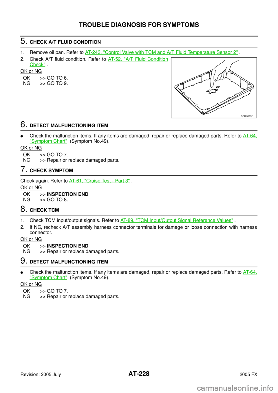
5. CHECK A/T FLUID CONDITION
1. Remove oil pan. Refer to AT- 2 4 3 , "
Control Valve with TCM and A/T Fluid Temperature Sensor 2" .
2. Check A/T fluid condition. Refer to AT- 5 2 , "
A/T Fluid Condition
Check" .
OK or NG
OK >> GO TO 6.
NG >> GO TO 9.
6. DETECT MALFUNCTIONING ITEM
�Check the malfunction items. If any items are damaged, repair or replace damaged parts. Refer to AT- 6 4 ,
"Symptom Chart" (Symptom No.49).
OK or NG
OK >> GO TO 7.
NG >> Repair or replace damaged parts.
7. CHECK SYMPTOM
Check again. Refer to AT- 6 1 , "
Cruise Test - Part 3" .
OK or NG
OK >> INSPECTION END
NG >> GO TO 8.
8. CHECK TCM
1. Check TCM input/output signals. Refer to AT- 8 9 , "
TCM Input/Output Signal Reference Values" .
2. If NG, recheck A/T assembly harness connector terminals for damage or loose connection with harness connector.
OK or NG
OK >> INSPECTION END
NG >> Repair or replace damaged parts.
9. DETECT MALFUNCTIONING ITEM
�Check the malfunction items. If any items are damaged, repair or replace damaged parts. Refer to AT- 6 4 ,
"Symptom Chart" (Symptom No.49).
OK or NG
OK >> GO TO 7.
NG >> Repair or replace damaged parts.
SCIA5199E
Page 313 of 4731

AT-230
TROUBLE DIAGNOSIS FOR SYMPTOMS
Revision: 2005 July 2005 FX
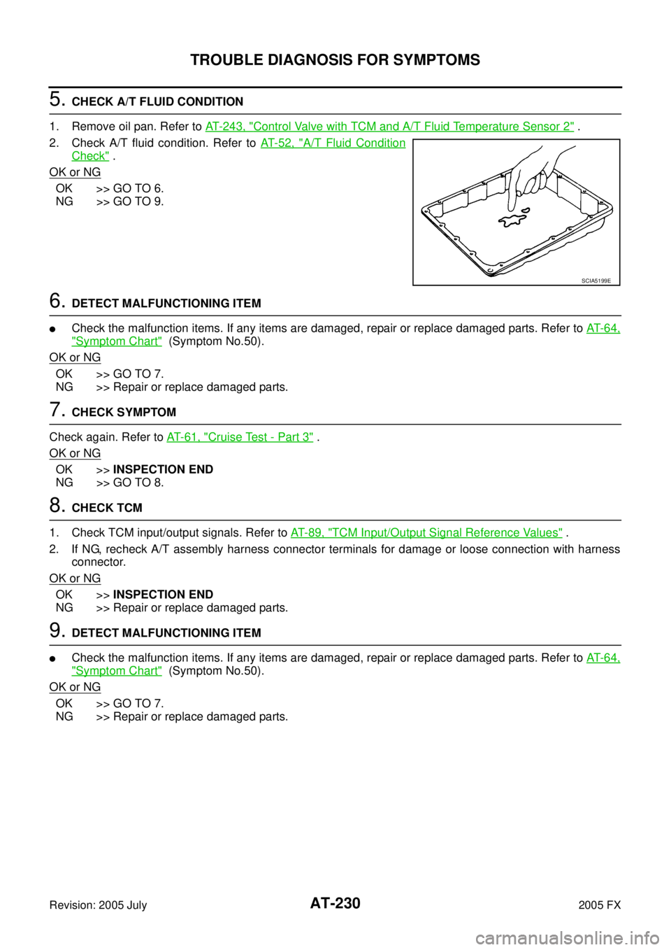
5. CHECK A/T FLUID CONDITION
1. Remove oil pan. Refer to AT- 2 4 3 , "
Control Valve with TCM and A/T Fluid Temperature Sensor 2" .
2. Check A/T fluid condition. Refer to AT- 5 2 , "
A/T Fluid Condition
Check" .
OK or NG
OK >> GO TO 6.
NG >> GO TO 9.
6. DETECT MALFUNCTIONING ITEM
�Check the malfunction items. If any items are damaged, repair or replace damaged parts. Refer to AT- 6 4 ,
"Symptom Chart" (Symptom No.50).
OK or NG
OK >> GO TO 7.
NG >> Repair or replace damaged parts.
7. CHECK SYMPTOM
Check again. Refer to AT- 6 1 , "
Cruise Test - Part 3" .
OK or NG
OK >> INSPECTION END
NG >> GO TO 8.
8. CHECK TCM
1. Check TCM input/output signals. Refer to AT- 8 9 , "
TCM Input/Output Signal Reference Values" .
2. If NG, recheck A/T assembly harness connector terminals for damage or loose connection with harness connector.
OK or NG
OK >> INSPECTION END
NG >> Repair or replace damaged parts.
9. DETECT MALFUNCTIONING ITEM
�Check the malfunction items. If any items are damaged, repair or replace damaged parts. Refer to AT- 6 4 ,
"Symptom Chart" (Symptom No.50).
OK or NG
OK >> GO TO 7.
NG >> Repair or replace damaged parts.
SCIA5199E
Page 315 of 4731

AT-232
TROUBLE DIAGNOSIS FOR SYMPTOMS
Revision: 2005 July 2005 FX
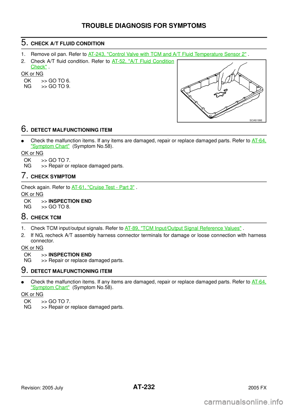
5. CHECK A/T FLUID CONDITION
1. Remove oil pan. Refer to AT- 2 4 3 , "
Control Valve with TCM and A/T Fluid Temperature Sensor 2" .
2. Check A/T fluid condition. Refer to AT- 5 2 , "
A/T Fluid Condition
Check" .
OK or NG
OK >> GO TO 6.
NG >> GO TO 9.
6. DETECT MALFUNCTIONING ITEM
�Check the malfunction items. If any items are damaged, repair or replace damaged parts. Refer to AT- 6 4 ,
"Symptom Chart" (Symptom No.58).
OK or NG
OK >> GO TO 7.
NG >> Repair or replace damaged parts.
7. CHECK SYMPTOM
Check again. Refer to AT- 6 1 , "
Cruise Test - Part 3" .
OK or NG
OK >> INSPECTION END
NG >> GO TO 8.
8. CHECK TCM
1. Check TCM input/output signals. Refer to AT- 8 9 , "
TCM Input/Output Signal Reference Values" .
2. If NG, recheck A/T assembly harness connector terminals for damage or loose connection with harness connector.
OK or NG
OK >> INSPECTION END
NG >> Repair or replace damaged parts.
9. DETECT MALFUNCTIONING ITEM
�Check the malfunction items. If any items are damaged, repair or replace damaged parts. Refer to AT- 6 4 ,
"Symptom Chart" (Symptom No.58).
OK or NG
OK >> GO TO 7.
NG >> Repair or replace damaged parts.
SCIA5199E
Page 326 of 4731
ON-VEHICLE SERVICE AT-243
D E
F
G H
I
J
K L
M A
B
AT
Revision: 2005 July 2005 FX
ON-VEHICLE SERVICEPFP:00000
Control Valve with TCM and A/T Fluid Temperature Sensor 2ACS0081E
COMPONENTS
CONTROL VALVE WITH TCM ASSEMBLY REMOVAL AND INSTALLATION
Removal
1. Disconnect the battery cable from negative terminal.
2. Drain ATF through drain plug.
3. Remove front cross bar. Refer to FSU-8, "
Components" .
4. Disconnect heated oxygen sensor 2 harness connector.
5. Disconnect A/T assembly harness connector.
1. Transmission 2. Snap ring 3. Sub-harness
4. Control valve with TCM 5. Bracket 6. A/T fluid temperature sensor 2
7. Oil pan gasket 8. Oil pan 9. Magnet
10. Drain plug 11. Drain plug gasket 12. Oil pan mounting bolt
13. Terminal cord assembly 14. O-ring
SCIA5478E
Page 334 of 4731

ON-VEHICLE SERVICE AT-251
D E
F
G H
I
J
K L
M A
B
AT
Revision: 2005 July 2005 FX
c. Tighten oil pan mounting bolts to the specified torque in numeri-
cal order shown in the figure after temporarily tightening them.
CAUTION:
Do not reuse oil pan mounting bolts.
16. Install drain plug to oil pan. CAUTION:
Do not reuse drain plug gasket.
17. Pull up A/T assembly harness connector. CAUTION:
Be careful not to damage connector.
18. Install snap ring to A/T assembly harness connector.
19. Connect A/T assembly harness connector.
20. Connect heated oxygen sensor 2 harness connector.
21. Install front cross bar. Refer to FSU-8, "
Components" .
22. Pour ATF into transmission assembly. Refer to AT- 1 2 , "
Chang-
ing A/T Fluid" .
23. Connect the battery cable to the negative terminal.
A/T FLUID TEMPERATURE SENSOR 2 REMOVAL AND INSTALLATION
Removal
1. Disconnect the battery cable from negative terminal.
2. Remove front cross bar. Refer to FSU-8, "
Components" .
3. Disconnect heated oxygen sensor 2 harness connector.
4. Drain ATF through drain plug.
5. Remove oil pan and oil pan gasket. : 7.9 N·m (0.81 kg-m, 70 in-lb)
: 34 N·m (3.5 kg-m, 25 ft-lb)
SCIA4113E
SCIA5038E
SCIA5039E
SCIA2308E
Page 335 of 4731
AT-252
ON-VEHICLE SERVICE
Revision: 2005 July 2005 FX
6. Check foreign materials in oil pan to help determine causes of
malfunction. If the ATF is very dark, smells burned, or contains
foreign particles, the frictional material (clutches, band) may
need replacement. A tacky film that will not wipe clean indicates
varnish build up. Varnish can cause valves, servo, and clutches
to stick and can inhibit pump pressure.
�If frictional material is detected, perform A/T fluid cooler
cleaning. Refer to AT- 1 5 , "
A/T Fluid Cooler Cleaning" .
7. Disconnect A/T fluid temperature sensor 2 connector. CAUTION:
Be careful not to damage connector.
8. Straighten terminal clip to free A/T fluid temperature sensor 2 harness.
9. Remove A/T fluid temperature sensor 2 with bracket from con- trol valve with TCM.
10. Remove bracket from A/T fluid temperature sensor 2.
SCIA5199E
SCIA5023E
SCIA5146E
SCIA5302E
SCIA5264E
Page 336 of 4731
ON-VEHICLE SERVICE AT-253
D E
F
G H
I
J
K L
M A
B
AT
Revision: 2005 July 2005 FX
Installation
1. Install A/T fluid temperature sensor 2 to bracket.
2. Install A/T fluid temperature sensor 2 (with bracket) in control
valve with TCM.
3. Connect A/T fluid temperature sensor 2 connector.
4. Securely fasten A/T fluid temperature sensor 2 harness with ter- minal clip.
5. Install oil pan to transmission case.
a. Install oil pan gasket to oil pan. CAUTION:
�Do not reuse oil pan gasket.
�Install it in the direction to align hole positions.
�Completely remove all moisture, oil and old gasket, etc. from oil pan mounting surface.
SCIA5264E
: 7.9 N·m (0.81 kg-m, 70 in-lb)
SCIA5302E
SCIA5023E
SCIA5146E
Page 366 of 4731
OVERHAUL AT-283
D E
F
G H
I
J
K L
M A
B
AT
Revision: 2005 July 2005 FX
7. Pawl shaft 8. Seal ring 9. Needle bearing
10. Revolution sensor 11. Parking gear 12. Output shaft
13. Bearing race 14. Needle bearing 15. Manual plate
16. Parking rod 17. Manual shaft oil seal 18. Manual shaft
19. O-ring 20. Band servo anchor end pin 21. Detent spring
22. Spacer 23. Seal ring 24. Snap ring
25. Return spring 26. O-ring 27. Servo assembly
28. Snap ring 29. Sub-harness 30. Control valve with TCM
31. Bracket 32. A/T fluid temperature sensor 2 33. Oil pan
34. Magnet 35. Drain plug 36. Drain plug gasket
37. Oil pan mounting bolt 38. Oil pan gasket 39. Terminal cord assembly
40. O-ring 41. Retaining pin 42. Transmission case
Refer to GI section to make sure icons (symbol marks) in the figure. Refer to GI-10, "
Components" .
However, refer to the following symbol for others.
: Apply Genuine Anaerobic Gasket or equivalent. Refer to GI-48, "
Recommended Chemical Products and Sealants" .