CHARGING SYSTEM SC-29
C
D E
F
G H
I
J
L
M A
B
SC
Revision: 2005 July 2005 FX
PRELIMINARY INSPECTION
1. CHECK BATTERY TERMINALS CONNECTION
Check if battery terminals are clean and tight.
OK or NG
OK >> GO TO 2.
NG >> Repair battery terminals connection.
2. CHECK FUSE AND FUSIBLE LINK
Check for blown alternator and combination meter fuses.
OK or NG
OK >> GO TO 3.
NG >> If fuse is blown, be sure eliminate cause of malfunction before installing new fuse.
3. CHECK “E” TERMINAL CONNECTION
Check if “E” terminal is clean and tight.
OK or NG
OK >> GO TO 4.
NG >> Repair “E” terminal connection.
4. CHECK ALTERNATOR DRIVE BELT TENSION
Check alternator drive belt tension. Refer to EM-173, "
Checking Drive Belts" (VK45DE) or EM-15, "Checking
Drive Belts" (VQ35DE).
OK or NG
OK >> INSPECTION END
NG >> Repair as needed.
Unit Power source (Power supply terminals) Fuse No.
Alternator Battery (“S” terminal) 33
Combination meter Ignition switch ON (“L” terminal) 14
SE-36
AUTOMATIC DRIVE POSITIONER
Revision: 2005 July 2005 FX
CHECK POWER SUPPLY AND GROUND
1. CHECK FUSE
Check if any of the following fuses in the BCM are blown.
�Check 50A fusible link (letter M , located in the fuse and fusible link box.)
�Check 15A fuse [No.22, located in the fuse block (J/B)]
�Check 10A fuse [No.1, located in the fuse block (J/B)]
�Check 10A fuse [No.6, located in the fuse block (J/B)]
NOTE:
Refer to SE-15, "
Component Parts and Harness Connector Location" .
OK or NG
OK >> GO TO 2.
NG >> If fuse is blown out, be sure to eliminate cause of malfunction before installing new fuse. Refer to
SE-15, "
Component Parts and Harness Connector Location" .
2. CHECK POWER SUPPLY CIRCUIT (BCM)
1. Turn ignition switch OFF.
2. Disconnect BCM connector.
3. Check voltage between BCM connector and ground.
OK or NG
OK >> GO TO 3.
NG >> Check harness for open and short between BCM and fuse or fusible link.
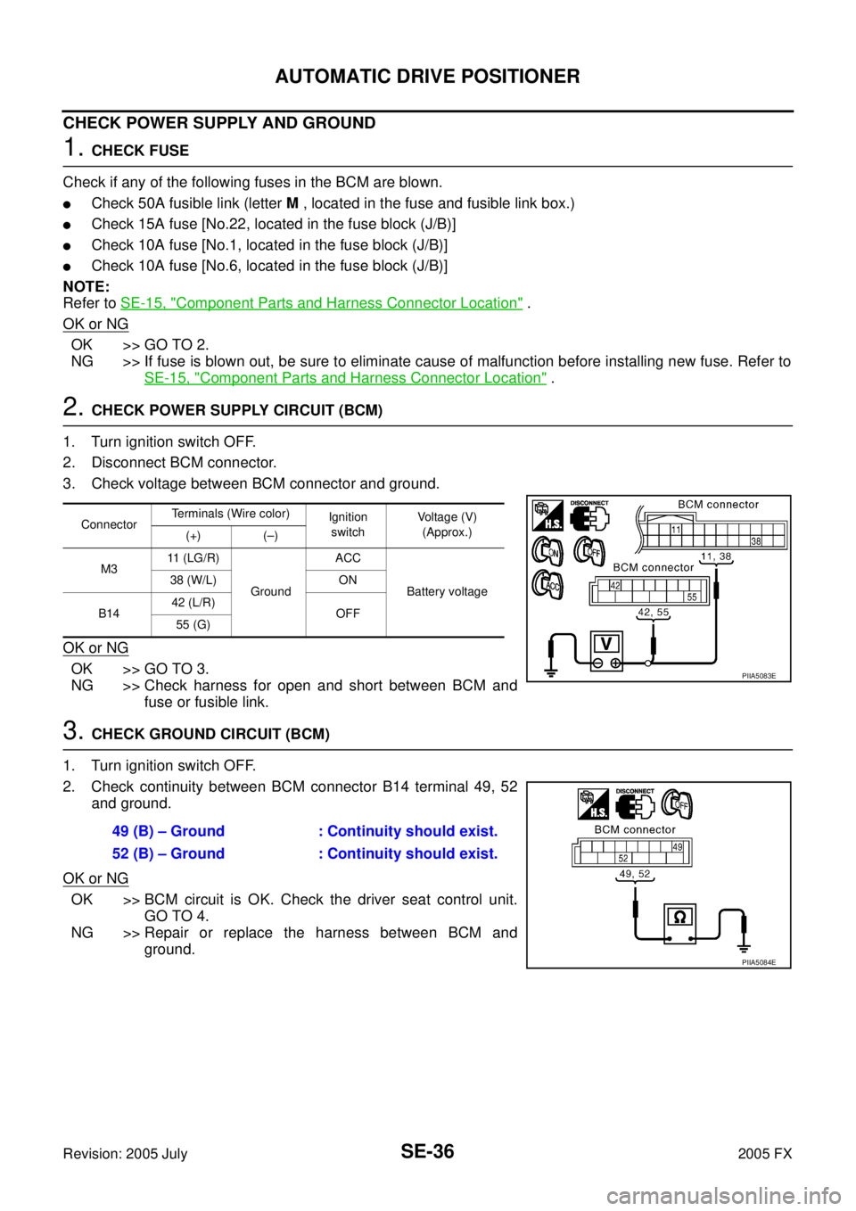
3. CHECK GROUND CIRCUIT (BCM)
1. Turn ignition switch OFF.
2. Check continuity between BCM connector B14 terminal 49, 52 and ground.
OK or NG
OK >> BCM circuit is OK. Check the driver seat control unit. GO TO 4.
NG >> Repair or replace the harness between BCM and ground.
Connector Terminals (Wire color)
Ignition
switch Voltage (V)
(Approx.)
(+) (–)
M3 11 (LG/R)
Ground ACC
Battery voltage
38 (W/L) ON
B14 42 (L/R)
OFF
55 (G)
PIIA5083E
49 (B) – Ground : Continuity should exist.
52 (B) – Ground : Continuity should exist.
PIIA5084E