INTEGRATED DISPLAY SYSTEM AV-59
C
D E
F
G H
I
J
L
M A
B
AV
Revision: 2005 July 2005 FX
MAINT Switch (Maintenance Switch)
�When “MAINT” switch is pressed, display vehicle information screen. As vehicle information, it indicates
engine oil, tire rotation, tire pressure.
�Pressing “MAINT” switch once cycles display from engine oil →tire rotation →tire pressure →display
OFF →engine oil.
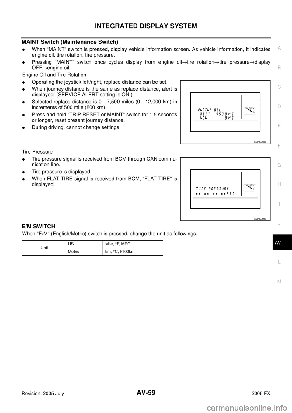
Engine Oil and Tire Rotation
�Operating the joystick left/right, replace distance can be set.
�When journey distance is the same as replace distance, alert is
displayed. (SERVICE ALERT setting is ON.)
�Selected replace distance is 0 - 7,500 miles (0 - 12,000 km) in
increments of 500 mile (800 km).
�Press and hold “TRIP RESET or MAINT” switch for 1.5 seconds
or longer, reset present journey distance.
�During driving, cannot change settings.
Tire Pressure
�Tire pressure signal is received from BCM through CAN commu-
nication line.
�Tire pressure is displayed.
�When FLAT TIRE signal is received from BCM, “FLAT TIRE” is
displayed.
E/M SWITCH
When “E/M” (English/Metric) switch is pressed, change the unit as followings.
SKIA5918E
SKIA5919E
Unit US Mile,
°F, M P G
Metric km, °C, l/100km
AV-102
NAVIGATION SYSTEM
Revision: 2005 July 2005 FX
TRIP 1 OR TRIP 2
�Elapsed Time, Driving Distance and Average Speed are dis-
played as Trip 1 information or Trip 2 information.
�The way to reset is by pushing the “Reset” switch or by keeping
pushing “TRIP” button more than 1.5 seconds.
FUEL ECONOMY
�Average Fuel Economy, Distance to Empty, Fuel Economy are
displayed as Fuel Economy information.
�The way to reset is by pushing the “Reset” switch or by keeping
pushing “TRIP” button more than 1.5 seconds.
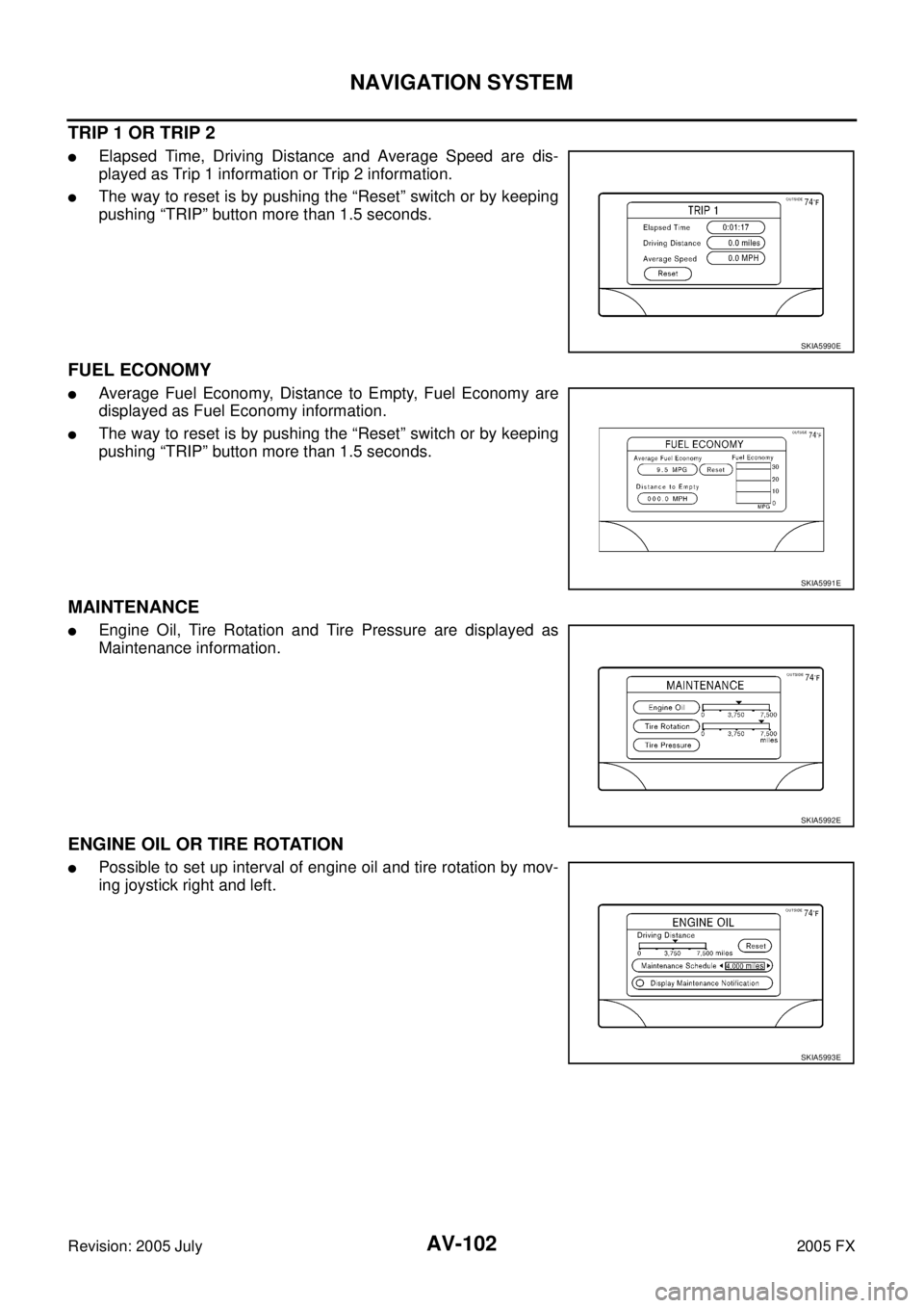
MAINTENANCE
�Engine Oil, Tire Rotation and Tire Pressure are displayed as
Maintenance information.
ENGINE OIL OR TIRE ROTATION
�Possible to set up interval of engine oil and tire rotation by mov-
ing joystick right and left.
SKIA5990E
SKIA5991E
SKIA5992E
SKIA5993E
UNIFIED METER AND A/C AMP DI-29
C
D E
F
G H
I
J
L
M A
B
DI
Revision: 2005 July 2005 FX
FA I L - S A F E
Solution When Communication Error Between the Unified Meter & A/C Amp. and the Combi-
nation Meter
CAN Communication System DescriptionAKS007Z1
CAN (Controller Area Network) is a serial communication line for real time application. It is an on-vehicle mul-
tiplex communication line with high data communication speed and excellent error detection ability. Many elec-
tronic control units are equipped onto a vehicle, and each control unit shares information and links with other
control units during operation (not independent). In CAN communication, control units are connected with 2
communication lines (CAN H line, CAN L line) allowing a high rate of information transmission with less wiring.
Each control unit transmits/receives data but selectively reads required data only.
CAN Communication UnitAKS007YX
Refer to LAN-30, "CAN Communication Unit" in “LAN SYSTEM”.
Function Specifications
Speedometer Return to zero when discontinuing communication or receiving
irregular data.
Tachometer Reset to zero by suspending communication.
Fuel gauge
Water temperature gauge
Illumination control Combination meter illumination When suspending communication, change to nighttime mode.
Odo/trip meter Integrate in response to 8-pulse input.
A/T position indicator The display turns off by suspending communication.
Warning buzzer The warning buzzer turns off by suspending communication.
Warning lamp/indicator lamp ABS warning lamp
The lamp turns on by suspending communication.
VDC OFF indicator
SLIP indicator
Brake warning lamp
Door warning lamp
The lamp turns off by suspending communication.
Low tire pressure warning lamp
SET indicator lamp
CRUISE indicator lamp
AWD warning lamp
ICC warning lamp
A/T CHECK warning lamp
Oil pressure warning lamp
Snow mode indicator lamp
Turn signal indicator
Malfunction indicator lamp
High beam indicator