Page 952 of 4731

INTELLIGENT KEY SYSTEM BL-137
C
D E
F
G H
J
K L
M A
B
BL
Revision: 2005 July 2005 FX
3. CHECK UNLOCK SENSOR GROUND CIRCUIT
Check continuity between front door lock assembly (driver side) connector D10 terminal 5 (B) and ground.
OK or NG
OK >> GO TO 4.
NG >> Repair or replace harness.
4. CHECK INTELLIGENT KEY UNIT OUTPUT SIGNAL
1. Connect Intelligent Key unit connector.
2. Driver side door lock is locked.
3. Check voltage between Intelligent Key unit connector M34 terminal 28 (W/B) and ground.
OK or NG
OK >> Replace front door lock assembly (driver side).
NG >> Replace Intelligent Key unit.
Check Door Request SwitchAIS004NH
1. CHECK DOOR REQUEST SWITCH
With CONSULT-II
Display “DR REQ SW” (driver door), “AS REQ SW” (passenger
door) and “BD/TR REQ SW” (back door) on DATA MONITOR
screen, and check if ON-OFF display is linked to door request switch
operation.
OK or NG
OK >> Door request switch is OK.
NG >> GO TO 2. 5 (B) – Ground : Continuity should exist.
PIIA6804E
28 (W/B) – Ground : Approx. 5V
PIIA6802E
Press door request switch. : ON
Release door request switch. : OFF
PIIB1361E
Page 1015 of 4731
BL-200
VEHICLE SECURITY (THEFT WARNING) SYSTEM
Revision: 2005 July 2005 FX
CONSULT-II Function (BCM)AIS004P0
CAUTION:
CONSULT-II is used with no connection of CONSULT-II CONVERTER, malfunction might be detected in
self-diagnosis depending on control unit with carry out CAN communication.
CONSULT-II can display each diagnostic item using the diagnostic test modes shown.
1. Turn ignition switch OFF.
2. Connect CONSULT-II and CONSULT-II CONVERTER to data link connector.
3. Turn ignition switch ON.
4. Touch “START (NISSAN BASED VHCL)”.
5. Touch “BCM”. If “BCM” is not indicated, go to GI-39, "
CONSULT-II Data Link
Connector (DLC) Circuit" .
BCM diagnosis
test item Check item diagnosis test mode Content
Theft alm WORK SUPPORT Change setting of each function.
DATA MONITOR Displays the input data of BCM real time. ACTIVE TEST Gives a drive signal to a load to check the operation.
PBIB1503E
BCIA0029E
BCIA0030E
Page 1016 of 4731
VEHICLE SECURITY (THEFT WARNING) SYSTEM BL-201
C
D E
F
G H
J
K L
M A
B
BL
Revision: 2005 July 2005 FX
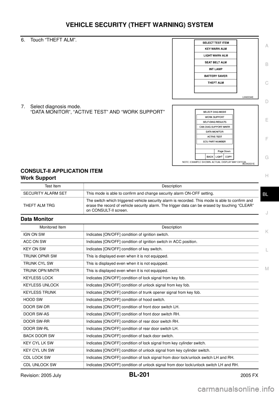
6. Touch “THEFT ALM”.
7. Select diagnosis mode.
“DATA MONITOR”, “ACTIVE TEST” AND “WORK SUPPORT”
CONSULT-II APPLICATION ITEM
Work Support
Data Monitor
LIIA0034E
BCIA0031E
Test Item Description
SECURITY ALARM SET This mode is able to confirm and change security alarm ON-OFF setting.
THEFT ALM TRG The switch which triggered vehicle security alarm is recorded. This mode is able to confirm and
erase the record of vehicle security alarm. The trigger data can be erased by touching “CLEAR”
on CONSULT-II screen.
Monitored Item Description
IGN ON SW Indicates [ON/OFF] condition of ignition switch.
ACC ON SW Indicates [ON/OFF] condition of ignition switch in ACC position.
KEY ON SW Indicates [ON/OFF] condition of key switch.
TRUNK OPNR SW This is displayed even when it is not equipped.
TRUNK CYL SW This is displayed even when it is not equipped.
TRUNK OPN MNTR This is displayed even when it is not equipped.
KEYLESS LOCK Indicates [ON/OFF] condition of lock signal from key fob.
KEYLESS UNLOCK Indicates [ON/OFF] condition of unlock signal from key fob.
KEYLESS TRUNK Indicates [ON/OFF] condition of trunk opener signal from key fob.
HOOD SW Indicates [ON/OFF] condition of hood switch.
DOOR SW-DR Indicates [ON/OFF] condition of front door switch LH.
DOOR SW-AS Indicates [ON/OFF] condition of front door switch RH.
DOOR SW-RR Indicates [ON/OFF] condition of rear door switch RH.
DOOR SW-RL Indicates [ON/OFF] condition of rear door switch LH.
BACK DOOR SW Indicates [ON/OFF] condition of back door switch.
KEY CYL LK SW Indicates [ON/OFF] condition of lock signal from key cylinder switch.
KEY CYL UN SW Indicates [ON/OFF] condition of unlock signal from key cylinder switch.
CDL LOCK SW Indicates [ON/OFF] condition of lock signal from door lock/unlock switch LH and RH.
CDL UNLOCK SW Indicates [ON/OFF] condition of unlock signal from door lock/unlock switch LH and RH.
Page 1026 of 4731
VEHICLE SECURITY (THEFT WARNING) SYSTEM BL-211
C
D E
F
G H
J
K L
M A
B
BL
Revision: 2005 July 2005 FX
Diagnostic Procedure 2AIS004P5
SECURITY INDICATOR LAMP CHECK
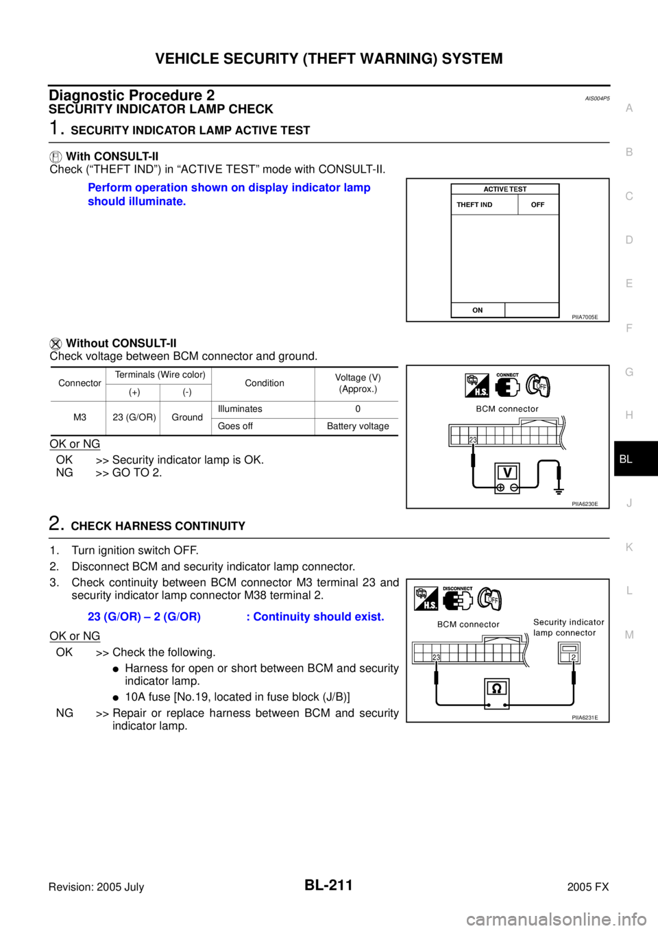
1. SECURITY INDICATOR LAMP ACTIVE TEST
With CONSULT-II
Check (“THEFT IND”) in “ACTIVE TEST” mode with CONSULT-II.
Without CONSULT-II
Check voltage between BCM connector and ground.
OK or NG
OK >> Security indicator lamp is OK.
NG >> GO TO 2.
2. CHECK HARNESS CONTINUITY
1. Turn ignition switch OFF.
2. Disconnect BCM and security indicator lamp connector.
3. Check continuity between BCM connector M3 terminal 23 and security indicator lamp connector M38 terminal 2.
OK or NG
OK >> Check the following.
�Harness for open or short between BCM and security
indicator lamp.
�10A fuse [No.19, located in fuse block (J/B)]
NG >> Repair or replace harness between BCM and security indicator lamp.
Perform operation shown on display indicator lamp
should illuminate.
PIIA7005E
Connector Terminals (Wire color)
Condition Voltage (V)
(Approx.)
(+) (-)
M3 23 (G/OR) Ground Illuminates 0
Goes off Battery voltage
PIIA6230E
23 (G/OR) – 2 (G/OR) : Continuity should exist.
PIIA6231E
Page 1040 of 4731
IVIS (INFINITI VEHICLE IMMOBILIZER SYSTEM-NATS) BL-225
C
D E
F
G H
J
K L
M A
B
BL
Revision: 2005 July 2005 FX
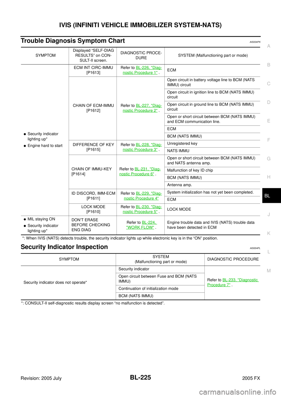
Trouble Diagnosis Symptom ChartAIS004PK
*: When IVIS (NATS) detects trouble, the security indicator lights up while electronic key is in the “ON” position.
Security Indicator InspectionAIS004PL
*: CONSULT-II self-diagnostic results display screen “no malfunction is detected”. SYMPTOM
Displayed “SELF-DIAG
RESULTS” on CON- SULT-II screen. DIAGNOSTIC PROCE-
DURE SYSTEM (Malfunctioning part or mode)
�Security indicator
lighting up*
�Engine hard to start ECM INT CIRC-IMMU
[P1613] Refer to
BL-226, "
Diag-
nostic Procedure 1" . ECM
CHAIN OF ECM-IMMU [P1612] Refer to
BL-227, "
Diag-
nostic Procedure 2" . Open circuit in battery voltage line to BCM (NATS
IMMU) circuit
Open circuit in ignition line to BCM (NATS IMMU)
circuit
Open circuit in ground line to BCM (NATS IMMU)
circuit
Open or short circuit between BCM (NATS IMMU)
and ECM communication line.
ECM
BCM (NATS IMMU)
DIFFERENCE OF KEY [P1615] Refer to
BL-228, "
Diag-
nostic Procedure 3" . Unregistered key
NATS IMMU
CHAIN OF IMMU-KEY
[P1614] Refer to
BL-231, "
Diag-
nostic Procedure 6" . Open or short circuit between BCM (NATS IMMU)
and NATS antenna amp.
Malfunction of key ID chip
BCM (NATS IMMU)
Antenna amp.
ID DISCORD, IMM-ECM [P1611] Refer to
BL-229, "
Diag-
nostic Procedure 4"
System initialization has not yet been completed.
ECM
LOCK MODE [P1610] Refer to
BL-230, "
Diag-
nostic Procedure 5" . LOCK MODE
�MIL staying ON
�Security indicator
lighting up* DON'T ERASE
BEFORE CHECKING
ENG DIAG Refer to
BL-224, "WORK FLOW" . Engine trouble data and IVIS (NATS) trouble data
have been detected in ECM
SYMPTOM SYSTEM
(Malfunctioning part or mode) DIAGNOSTIC PROCEDURE
Security indicator does not operate* Security indicator
Refer to BL-233, "
Diagnostic
Procedure 7" .
Open circuit between Fuse and BCM (NATS
IMMU)
Continuation of initialization mode
BCM (NATS IMMU)
Page 1041 of 4731
BL-226
IVIS (INFINITI VEHICLE IMMOBILIZER SYSTEM-NATS)
Revision: 2005 July 2005 FX
Diagnostic Procedure 1AIS004PM
Self-diagnostic results:
“ECM INT CIRC-IMMU” is displayed on CONSULT-II screen
1. CONFIRM SELF-DIAGNOSTIC RESULTS
Confirm that SELF-DIAGNOSTIC RESULTS “ECM INT CIRC-
IMMU” is displayed on CONSULT-II screen.
Does CONSULT-II screen display as shown in figure?
YES >> ECM is malfunctioning.
�Replace ECM.
�Perform initialization or re-communicating function.
–For initialization, refer to “CONSULT-II Operation
Manual NATS-IVIS/NVIS”.
–For re-communicating function, refer to BL-215, "ECM
Re-Communicating Function" .
NO >> GO TO BL-225, "
Trouble Diagnosis Symptom Chart" .
SEL314W
Page 1042 of 4731
IVIS (INFINITI VEHICLE IMMOBILIZER SYSTEM-NATS) BL-227
C
D E
F
G H
J
K L
M A
B
BL
Revision: 2005 July 2005 FX
Diagnostic Procedure 2AIS004PN
Self-diagnostic results:
“CHAIN OF ECM-IMMU” is display on CONSULT-II screen
First perform the “SELF-DIAG RESULTS” in “BCM” with CONSULT-II, then perform the trouble diagno-
sis of malfunction system indicated “SELF-DIAG RESULTS” of “BCM”. Refer to BCS-15, "
CAN Com-
munication Inspection Using CONSULT-II (Self-Diagnosis)" .
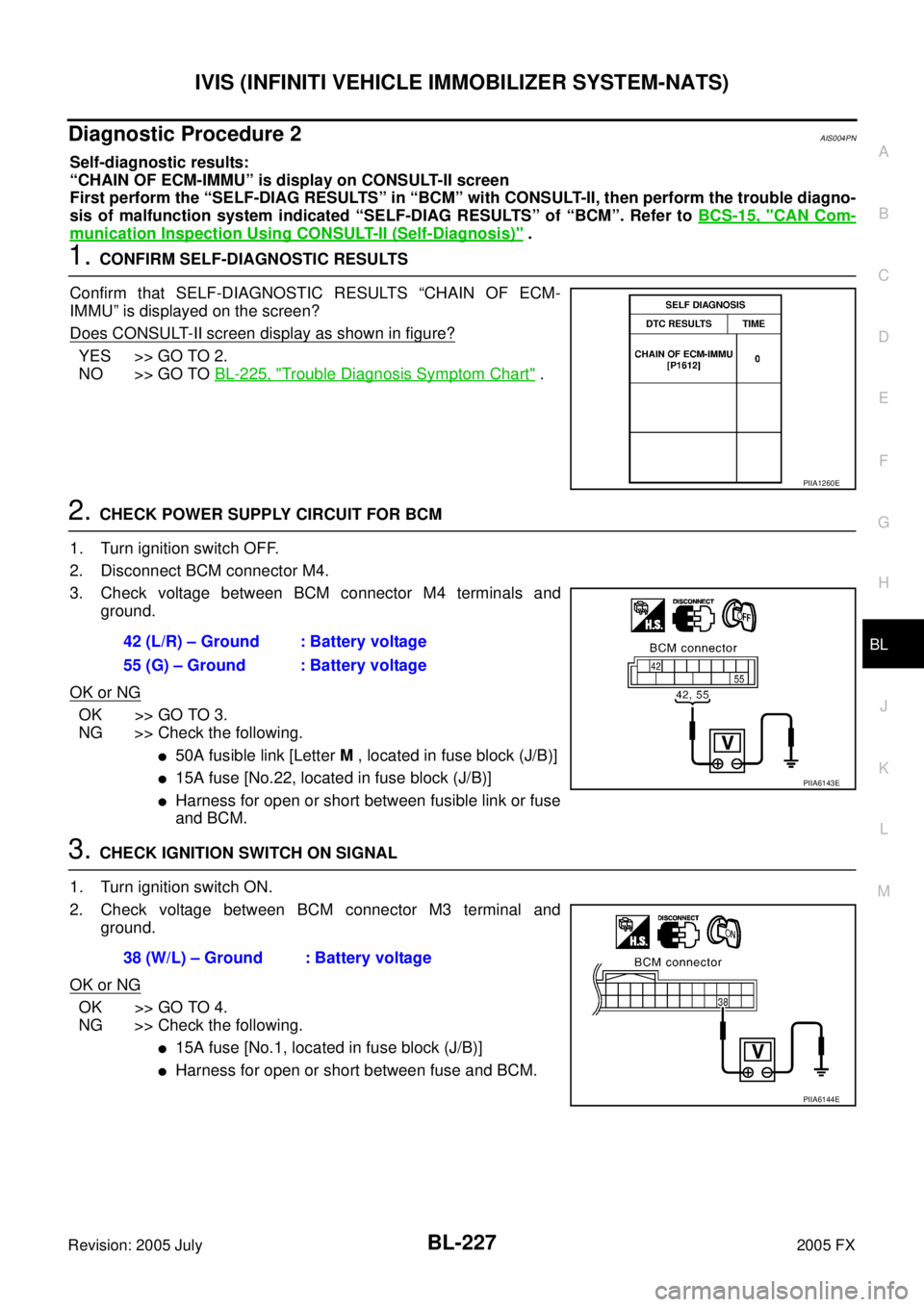
1. CONFIRM SELF-DIAGNOSTIC RESULTS
Confirm that SELF-DIAGNOSTIC RESULTS “CHAIN OF ECM-
IMMU” is displayed on the screen?
Does CONSULT-II screen display as shown in figure?
YES >> GO TO 2.
NO >> GO TO BL-225, "
Trouble Diagnosis Symptom Chart" .
2. CHECK POWER SUPPLY CIRCUIT FOR BCM
1. Turn ignition switch OFF.
2. Disconnect BCM connector M4.
3. Check voltage between BCM connector M4 terminals and ground.
OK or NG
OK >> GO TO 3.
NG >> Check the following.
�50A fusible link [Letter M , located in fuse block (J/B)]
�15A fuse [No.22, located in fuse block (J/B)]
�Harness for open or short between fusible link or fuse
and BCM.
3. CHECK IGNITION SWITCH ON SIGNAL
1. Turn ignition switch ON.
2. Check voltage between BCM connector M3 terminal and ground.
OK or NG
OK >> GO TO 4.
NG >> Check the following.
�15A fuse [No.1, located in fuse block (J/B)]
�Harness for open or short between fuse and BCM.
PIIA1260E
42 (L/R) – Ground : Battery voltage
55 (G) – Ground : Battery voltage
PIIA6143E
38 (W/L) – Ground : Battery voltage
PIIA6144E
Page 1043 of 4731
BL-228
IVIS (INFINITI VEHICLE IMMOBILIZER SYSTEM-NATS)
Revision: 2005 July 2005 FX
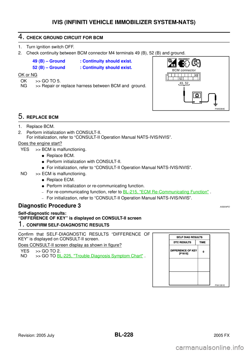
4. CHECK GROUND CIRCUIT FOR BCM
1. Turn ignition switch OFF.
2. Check continuity between BCM connector M4 terminals 49 (B), 52 (B) and ground.
OK or NG
OK >> GO TO 5.
NG >> Repair or replace harness between BCM and ground.
5. REPLACE BCM
1. Replace BCM.
2. Perform initialization with CONSULT-II. For initialization, refer to “CONSULT-II Operation Manual NATS-IVIS/NVIS”.
Does the engine start?
YES >> BCM is malfunctioning.
�Replace BCM.
�Perform initialization with CONSULT-II.
�For initialization, refer to “CONSULT-II Operation Manual NATS-IVIS/NVIS”.
NO >> ECM is malfunctioning.
�Replace ECM.
�Perform initialization or re-communicating function.
–For re-communicating function, refer to BL-215, "ECM Re-Communicating Function" .
–For initialization, refer to “CONSULT-II Operation Manual NATS-IVIS/NVIS”.
Diagnostic Procedure 3AIS004PO
Self-diagnostic results:
“DIFFERENCE OF KEY” is displayed on CONSULT-II screen
1. CONFIRM SELF-DIAGNOSTIC RESULTS
Confirm that SELF-DIAGNOSTIC RESULTS “DIFFERENCE OF
KEY” is displayed on CONSULT-II screen.
Does CONSULT-II screen display as shown in figure?
YES >> GO TO 2.
NO >> GO TO BL-225, "
Trouble Diagnosis Symptom Chart" .
49 (B) – Ground : Continuity should exist.
52 (B) – Ground : Continuity should exist.
PIIA5084E
PIIA1261E