Page 3433 of 4731
LAN-14
[CAN]
TROUBLE DIAGNOSES WORK FLOW
Revision: 2005 July 2005 FX
5. Confirm the unit name that “UNKWN” is displayed on the copy of “CAN DIAG SUPPORT MNTR” screen
of “BCM”, “METER A/C AMP” and “ABS” as well as “ENGINE”. And then, put a check mark to the check
sheet table.
NOTE:
�For “BCM”, “UNKWN” is displayed on “IPDM E/R” and “I-KEY”. But put a check mark to “IPDM E/R”
because “UNKWN” is listed on the column of reception diagnosis on the check sheet table.
�For “METER A/C AMP”, “UNKWN” is not displayed. Do not put a check to it.
�For “ABS”, “UNKWN” is displayed on “METER/M&A” and “ICC”. But, do not put a check mark to their
columns of reception diagnosis of the check sheet table because “UNKWN” is not listed.
PKIB5980E
Page 3443 of 4731
![INFINITI FX35 2005 Service Manual LAN-24
[CAN]
TROUBLE DIAGNOSES WORK FLOW
Revision: 2005 July 2005 FX
DESCRIPTION OF “CAN DIAG SUPPORT MNTR” SCREEN
FOR INTELLIGENT KEY UNIT
Display Results (Present)
�OK: Normal
�UNKWN: The diag](/manual-img/42/57020/w960_57020-3442.png "INFINITI FX35 2005 Service Manual LAN-24
[CAN]
TROUBLE DIAGNOSES WORK FLOW
Revision: 2005 July 2005 FX
DESCRIPTION OF “CAN DIAG SUPPORT MNTR” SCREEN
FOR INTELLIGENT KEY UNIT
Display Results (Present)
�OK: Normal
�UNKWN: The diag")
LAN-24
[CAN]
TROUBLE DIAGNOSES WORK FLOW
Revision: 2005 July 2005 FX
DESCRIPTION OF “CAN DIAG SUPPORT MNTR” SCREEN
FOR INTELLIGENT KEY UNIT
Display Results (Present)
�OK: Normal
�UNKWN: The diagnosed unit does not transmit or receive the applicable data normally.
�–: There is no received unit or the unit is not in the condition that reception diagnosis is performed.
Display Results (Past)
�OK: Normal
�0: There is malfunction now.
�1 ~ 39: Displays when it is normal at present and finds malfunction in the past. It increases like 0 →1→ 2...38 →39 after returning to the
normal condition whenever IGN OFF →ON. If it is over 39, it is fixed to 39 until the self-diagnostic results are erased. It returns to 0
when malfunction is detected again in the process.
�–: Undiagnosed
SKIB2359E
“SELECT SYSTEM” screen “CAN DIAG SUP-
PORT MNTR” screen Description Present Past
INTELLIGENT KEY TRANSMIT DIAG Make sure of normal transmission. OK/UNKWN/–
OK/0/1~39/–
ECM Make sure of normal reception from ECM. OK/UNKWN/–
METER/M&A Make sure of normal reception from unified meter and A/C
amp. OK/UNKWN/–
BCM/SEC Make sure of normal reception from BCM. OK/UNKWN/–
Page 3444 of 4731
TROUBLE DIAGNOSES WORK FLOW LAN-25
[CAN]
C
D E
F
G H
I
J
L
M A
B
LAN
Revision: 2005 July 2005 FX
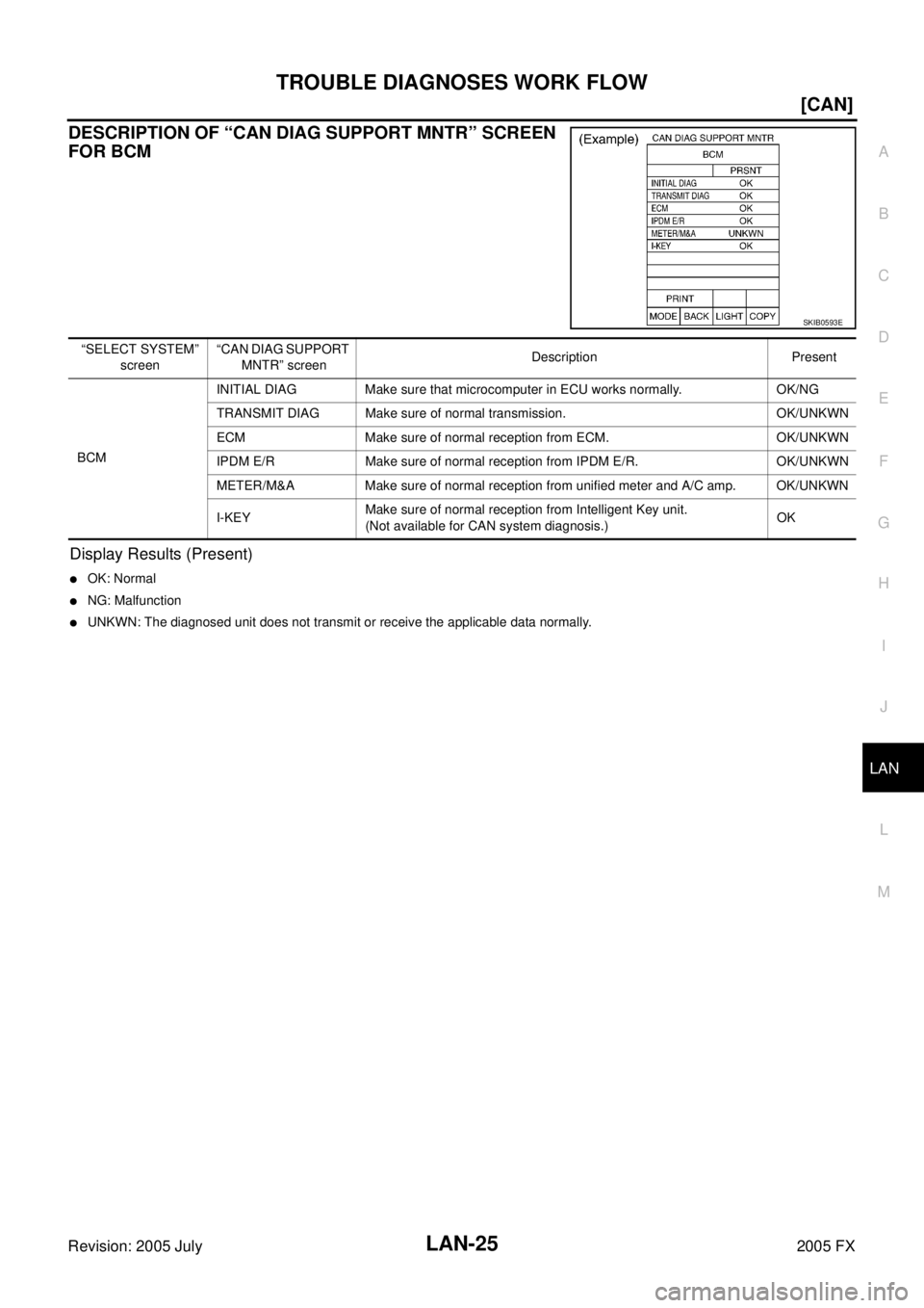
DESCRIPTION OF “CAN DIAG SUPPORT MNTR” SCREEN
FOR BCM
Display Results (Present)
�OK: Normal
�NG: Malfunction
�UNKWN: The diagnosed unit does not transmit or receive the applicable data normally.
SKIB0593E
“SELECT SYSTEM”
screen “CAN DIAG SUPPORT
MNTR” screen Description Present
BCM INITIAL DIAG Make sure that microcomputer in ECU works normally. OK/NG
TRANSMIT DIAG Make sure of normal transmission. OK/UNKWN
ECM Make sure of normal reception from ECM. OK/UNKWN
IPDM E/R Make sure of normal reception from IPDM E/R. OK/UNKWN
METER/M&A Make sure of normal reception from unified meter and A/C amp. OK/UNKWN
I-KEY Make sure of normal reception from Intelligent Key unit.
(Not available for CAN system diagnosis.) OK
Page 3446 of 4731
![INFINITI FX35 2005 Service Manual TROUBLE DIAGNOSES WORK FLOW LAN-27
[CAN]
C
D E
F
G H
I
J
L
M A
B
LAN
Revision: 2005 July 2005 FX
DESCRIPTION OF “CAN DIAG SUPPORT MNTR” SCREEN FOR UNIFIED METER AND A/C
AMP.
Display](/manual-img/42/57020/w960_57020-3445.png "INFINITI FX35 2005 Service Manual TROUBLE DIAGNOSES WORK FLOW LAN-27
[CAN]
C
D E
F
G H
I
J
L
M A
B
LAN
Revision: 2005 July 2005 FX
DESCRIPTION OF “CAN DIAG SUPPORT MNTR” SCREEN FOR UNIFIED METER AND A/C
AMP.
Display")
TROUBLE DIAGNOSES WORK FLOW LAN-27
[CAN]
C
D E
F
G H
I
J
L
M A
B
LAN
Revision: 2005 July 2005 FX
DESCRIPTION OF “CAN DIAG SUPPORT MNTR” SCREEN FOR UNIFIED METER AND A/C
AMP.
Display Results (Present)
�OK: Normal
�UNKWN: The diagnosed unit does not transmit or receive the applicable data normally.
�–: There is no received unit or the unit is not in the condition that reception diagnosis is performed.
Display Results (Past)
�OK: Normal
�0: There is malfunction now.
�1 ~ 39: Displays when it is normal at present and finds malfunction in the past. It increases like 0 →1→ 2...38 →39 after returning to the
normal condition whenever IGN OFF →ON. If it is over 39, it is fixed to 39 until the self-diagnostic results are erased. It returns to 0
when malfunction is detected again in the process.
�–: Undiagnosed
PKIB5986E
“SELECT SYSTEM” screen “CAN DIAG SUPPORT
MNTR” screen Description Present Past
METER A/C AMP TRANSMIT DIAG Make sure of normal transmission. OK/UNKWN/–
OK/0/1~39/–
ECM Make sure of normal reception from ECM. OK/UNKWN/–
TCM Make sure of normal reception from TCM. OK/UNKWN/–
BCM/SEC Make sure of normal reception from BCM. OK/UNKWN/–
VDC/TCS/ABS Make sure of normal reception from ABS actuator
and electric unit (control unit). OK/UNKWN/–
IPDM E/R IPDM E/R is not diagnosed. –
DISPLAY Make sure of normal reception from display control
unit. OK/UNKWN/–
Make sure of normal reception from display unit. OK/UNKWN/–
I-KEY Make sure of normal reception from Intelligent Key
unit. OK/UNKWN/–
EPS EPS is not diagnosed. –
AWD/4WD Make sure of normal reception from AWD control
unit. OK/UNKWN/–
e4WD e4WD is not diagnosed. –
ICC Make sure of normal reception from ICC unit. OK/UNKWN/–
LANE KEEP LANE KEEP is not diagnosed. –
TIRE-P Make sure of normal reception from BCM.
(Not available for CAN system diagnosis.) OK/UNKWN
Page 3449 of 4731
![INFINITI FX35 2005 Service Manual LAN-30
[CAN]
CAN COMMUNICATION
Revision: 2005 July 2005 FX
CAN COMMUNICATIONPFP:23710
System DescriptionAKS007GA
CAN (Controller Area Network) is a serial communication line for real time application.](/manual-img/42/57020/w960_57020-3448.png "INFINITI FX35 2005 Service Manual LAN-30
[CAN]
CAN COMMUNICATION
Revision: 2005 July 2005 FX
CAN COMMUNICATIONPFP:23710
System DescriptionAKS007GA
CAN (Controller Area Network) is a serial communication line for real time application.")
LAN-30
[CAN]
CAN COMMUNICATION
Revision: 2005 July 2005 FX
CAN COMMUNICATIONPFP:23710
System DescriptionAKS007GA
CAN (Controller Area Network) is a serial communication line for real time application. It is an on-vehicle mul-
tiplex communication line with high data communication speed and excellent error detection ability. Many elec-
tronic control units are equipped onto a vehicle, and each control unit shares information and links with other
control units during operation (not independent). In CAN communication, control units are connected with 2
communication lines (CAN H line, CAN L line) allowing a high rate of information transmission with less wiring.
Each control unit transmits/receives data but selectively reads required data only.
CAN Communication UnitAKS007Z4
Go to CAN system, when selecting your CAN system type from the following table.
× : Applicable
TYPE 1/TYPE 2/TYPE 9
System Diagram
�Ty p e 1
Body type Wagon
Axle 2WD AWD
Engine VQ35DE VQ35DE/VK45DE
Transmission A/T
Brake control VDC
Navigation system ×× ××
ICC system ×× ××
Intelligent Key system ×× ××
Lane departure warning system ×× ××
Automatic drive positioner ×××× ××××
CAN system type 9 1 2 3 4 10 5 6 7 8
CAN system trouble diagnosis LAN-
400LAN-47LAN-85LAN-
126
LAN-
171
LAN-
434
LAN-
219
LAN-
260
LAN-
304
LAN-
351
PKIB4203E
Page 3450 of 4731
CAN COMMUNICATION LAN-31
[CAN]
C
D E
F
G H
I
J
L
M A
B
LAN
Revision: 2005 July 2005 FX
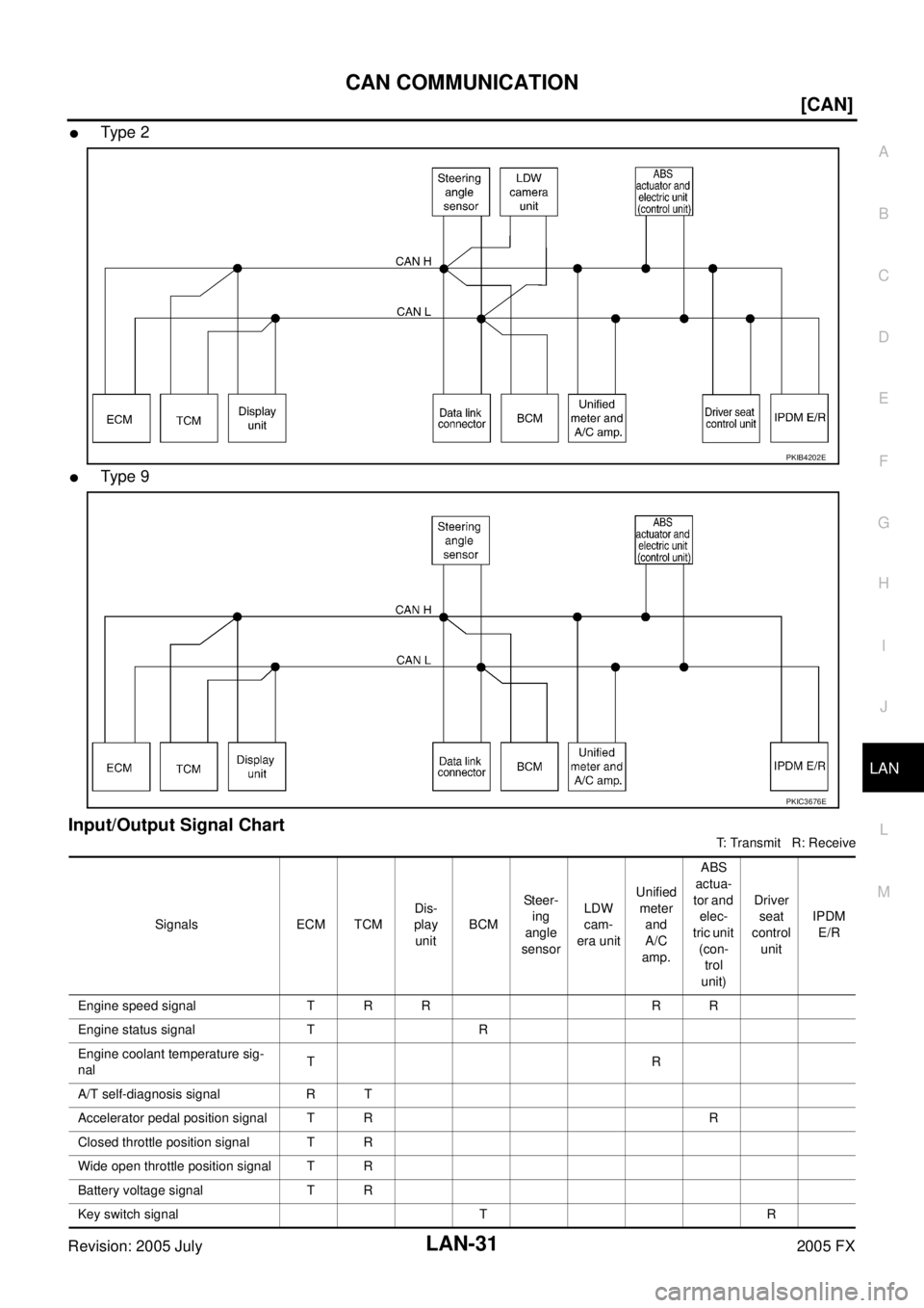
�Ty pe 2
�Ty pe 9
Input/Output Signal Chart
T: Transmit R: Receive
PKIB4202E
PKIC3676E
Signals ECM TCM Dis-
play unit BCM St e e r-
ing
angle
sensor LDW
cam-
era unit Unified
meter and
A/C
amp. ABS
actua-
tor and elec-
tric unit (con-trol
unit) Driver
seat
control unit IPDM
E/R
Engine speed signal T R R R R
Engine status signal T R
Engine coolant temperature sig-
nal TR
A/T self-diagnosis signal R T
Accelerator pedal position signal T R R
Closed throttle position signal T R
Wide open throttle position signal T R
Battery voltage signal T R
Key switch signal T R
Page 3451 of 4731
![INFINITI FX35 2005 Service Manual LAN-32
[CAN]
CAN COMMUNICATION
Revision: 2005 July 2005 FX
Ignition switch signal T R R
P range signal T R R
Stop lamp switch signal R T
Fuel consumption monitor signal TR
RT
Turbine revolution s](/manual-img/42/57020/w960_57020-3450.png "INFINITI FX35 2005 Service Manual LAN-32
[CAN]
CAN COMMUNICATION
Revision: 2005 July 2005 FX
Ignition switch signal T R R
P range signal T R R
Stop lamp switch signal R T
Fuel consumption monitor signal TR
RT
Turbine revolution s")
LAN-32
[CAN]
CAN COMMUNICATION
Revision: 2005 July 2005 FX
Ignition switch signal T R R
P range signal T R R
Stop lamp switch signal R T
Fuel consumption monitor signal TR
RT
Turbine revolution signal R T
Output shaft revolution signal R T R
A/C switch signal R T
A/C compressor request signal T R
A/C compressor feedback signal T R
Blower fan motor switch signal R T
A/C switch/indicator signal TR
RT
Cooling fan speed request signal T R
Position light request signal R T R R
Low beam request signal T R
Low beam status signal R T
High beam request signal T R R
High beam status signal R T
Front fog light request signal T R
Day time running light request
signal TR
Turn LED burnout status signal R T
Vehicle speed signal RR T
RRRR T R
Sleep wake up signal T R R
Door switch signal R T R R R
Turn indicator signal T R R
Key fob ID signal T R
Key fob door unlock signal T R
Oil pressure switch signal RT
TR
Buzzer output signal T R
Fuel level sensor signal R T
Fuel level low warning signal R T
ASCD SET lamp signal T R
ASCD CRUISE lamp signal T R
Malfunction indicator lamp signal T R
ASCD operation signal T R
ASCD OD cancel request signal T R Signals ECM TCM
Dis-
play unit BCM Steer-
ing
angle
sensor LDW
cam-
era unit Unified
meter and
A/C
amp. ABS
actua-
tor and elec-
tric unit (con-trol
unit) Driver
seat
control unit IPDM
E/R
Page 3453 of 4731
LAN-34
[CAN]
CAN COMMUNICATION
Revision: 2005 July 2005 FX
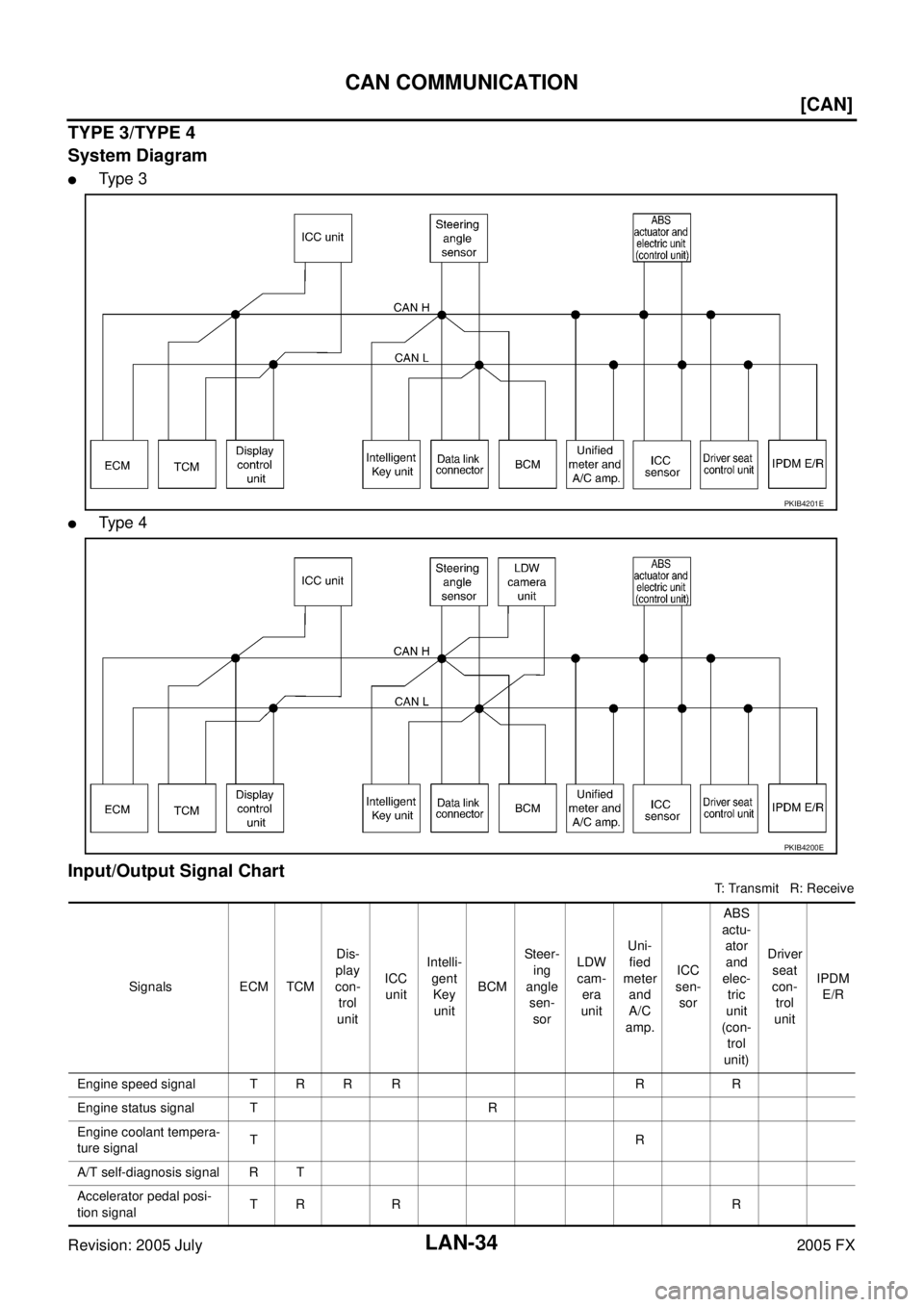
TYPE 3/TYPE 4
System Diagram
�Ty p e 3
�Ty p e 4
Input/Output Signal Chart
T: Transmit R: Receive
PKIB4201E
PKIB4200E
Signals ECM TCM Dis-
play
con- trol
unit ICC
unit Intelli-
gent Key
unit BCM St e e r-
ing
angle sen- sor LDW
cam- era
unit Uni-
fied
meter and
A/C
amp. ICC
sen- sor ABS
actu- ator
and
elec- tric
unit
(con- trol
unit) Driver
seat
con- trol
unit IPDM
E/R
Engine speed signal T R R R R R
Engine status signal T R
Engine coolant tempera-
ture signal TR
A/T self-diagnosis signal R T
Accelerator pedal posi-
tion signal TR R R
![INFINITI FX35 2005 Service Manual LAN-14
[CAN]
TROUBLE DIAGNOSES WORK FLOW
Revision: 2005 July 2005 FX
5. Confirm the unit name that “UNKWN” is displayed on the copy of “CAN DIAG SUPPORT MNTR” screen
of “BCM”, “METER A/](/manual-img/42/57020/w960_57020-3432.png "INFINITI FX35 2005 Service Manual LAN-14
[CAN]
TROUBLE DIAGNOSES WORK FLOW
Revision: 2005 July 2005 FX
5. Confirm the unit name that “UNKWN” is displayed on the copy of “CAN DIAG SUPPORT MNTR” screen
of “BCM”, “METER A/")