Page 1364 of 4731
LANE DEPARTURE WARNING SYSTEM DI-103
C
D E
F
G H
I
J
L
M A
B
DI
Revision: 2005 July 2005 FX
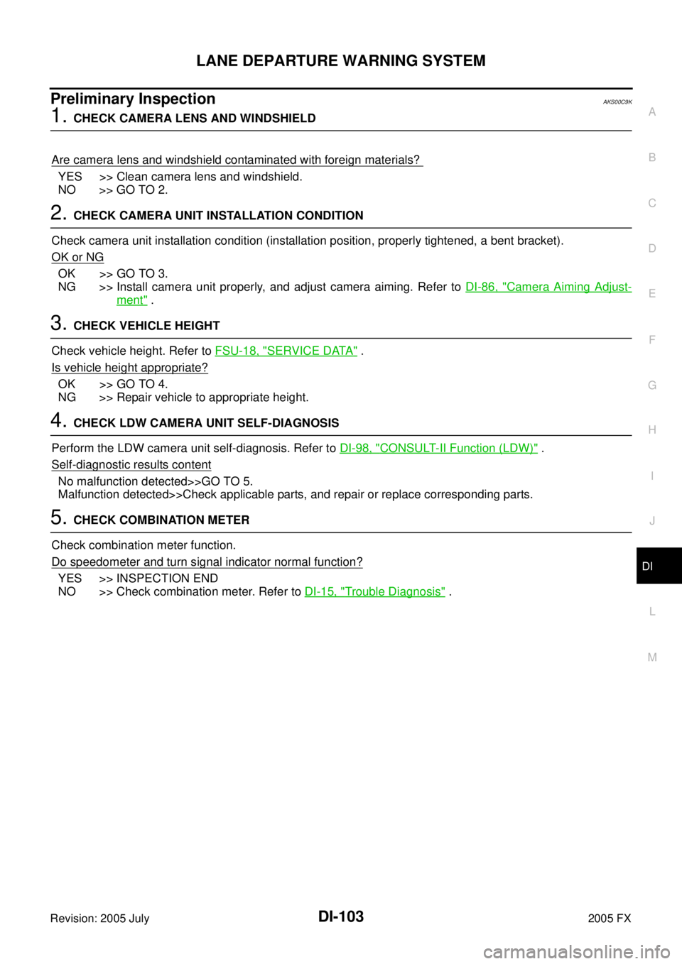
Preliminary InspectionAKS00C9K
1. CHECK CAMERA LENS AND WINDSHIELD
Are camera lens and windshield contaminated with foreign materials?
YES >> Clean camera lens and windshield.
NO >> GO TO 2.
2. CHECK CAMERA UNIT INSTALLATION CONDITION
Check camera unit installation condition (installation position, properly tightened, a bent bracket).
OK or NG
OK >> GO TO 3.
NG >> Install camera unit properly, and adjust camera aiming. Refer to DI-86, "
Camera Aiming Adjust-
ment" .
3. CHECK VEHICLE HEIGHT
Check vehicle height. Refer to FSU-18, "
SERVICE DATA" .
Is vehicle height appropriate?
OK >> GO TO 4.
NG >> Repair vehicle to appropriate height.
4. CHECK LDW CAMERA UNIT SELF-DIAGNOSIS
Perform the LDW camera unit self-diagnosis. Refer to DI-98, "
CONSULT-II Function (LDW)" .
Self
-diagnostic results content
No malfunction detected>>GO TO 5.
Malfunction detected>>Check applicable parts, and repair or replace corresponding parts.
5. CHECK COMBINATION METER
Check combination meter function.
Do speedometer and turn signal indicator normal function?
YES >> INSPECTION END
NO >> Check combination meter. Refer to DI-15, "
Trouble Diagnosis" .
Page 1367 of 4731
DI-106
LANE DEPARTURE WARNING SYSTEM
Revision: 2005 July 2005 FX
LDW Chime Circuit InspectionAKS00C83
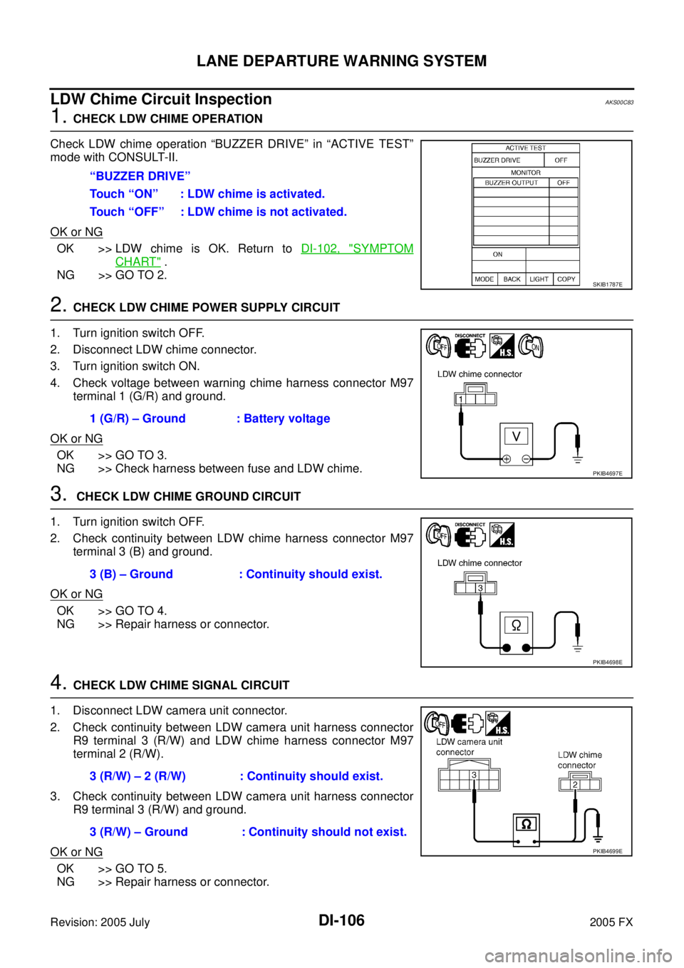
1. CHECK LDW CHIME OPERATION
Check LDW chime operation “BUZZER DRIVE” in “ACTIVE TEST”
mode with CONSULT-II.
OK or NG
OK >> LDW chime is OK. Return to DI-102, "SYMPTOM
CHART" .
NG >> GO TO 2.
2. CHECK LDW CHIME POWER SUPPLY CIRCUIT
1. Turn ignition switch OFF.
2. Disconnect LDW chime connector.
3. Turn ignition switch ON.
4. Check voltage between warning chime harness connector M97 terminal 1 (G/R) and ground.
OK or NG
OK >> GO TO 3.
NG >> Check harness between fuse and LDW chime.
3. CHECK LDW CHIME GROUND CIRCUIT
1. Turn ignition switch OFF.
2. Check continuity between LDW chime harness connector M97 terminal 3 (B) and ground.
OK or NG
OK >> GO TO 4.
NG >> Repair harness or connector.
4. CHECK LDW CHIME SIGNAL CIRCUIT
1. Disconnect LDW camera unit connector.
2. Check continuity between LDW camera unit harness connector R9 terminal 3 (R/W) and LDW chime harness connector M97
terminal 2 (R/W).
3. Check continuity between LDW camera unit harness connector R9 terminal 3 (R/W) and ground.
OK or NG
OK >> GO TO 5.
NG >> Repair harness or connector. “BUZZER DRIVE”
Touch “ON” : LDW chime is activated.
Touch “OFF” : LDW chime is not activated.
SKIB1787E
1 (G/R) – Ground : Battery voltage
PKIB4697E
3 (B) – Ground : Continuity should exist.
PKIB4698E
3 (R/W) – 2 (R/W) : Continuity should exist.
3 (R/W) – Ground : Continuity should not exist.
PKIB4699E
Page 1368 of 4731
LANE DEPARTURE WARNING SYSTEM DI-107
C
D E
F
G H
I
J
L
M A
B
DI
Revision: 2005 July 2005 FX
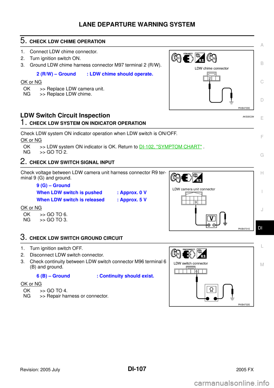
5. CHECK LDW CHIME OPERATION
1. Connect LDW chime connector.
2. Turn ignition switch ON.
3. Ground LDW chime harness connector M97 terminal 2 (R/W).
OK or NG
OK >> Replace LDW camera unit.
NG >> Replace LDW chime.
LDW Switch Circuit InspectionAKS00C84
1. CHECK LDW SYSTEM ON INDICATOR OPERATION
Check LDW system ON indicator operation when LDW switch is ON/OFF.
OK or NG
OK >> LDW system ON indicator is OK. Return to DI-102, "SYMPTOM CHART" .
NG >> GO TO 2.
2. CHECK LDW SWITCH SIGNAL INPUT
Check voltage between LDW camera unit harness connector R9 ter-
minal 9 (G) and ground.
OK or NG
OK >> GO TO 6.
NG >> GO TO 3.
3. CHECK LDW SWITCH GROUND CIRCUIT
1. Turn ignition switch OFF.
2. Disconnect LDW switch connector.
3. Check continuity between LDW switch connector M96 terminal 6 (B) and ground.
OK or NG
OK >> GO TO 4.
NG >> Repair harness or connector. 2 (R/W) – Ground : LDW chime should operate.
PKIB4700E
9 (G) – Ground
When LDW switch is pushed : Approx. 0 V
When LDW switch is released : Approx. 5 V
PKIB4701E
6 (B) – Ground : Continuity should exist.
PKIB4702E
Page 1369 of 4731
DI-108
LANE DEPARTURE WARNING SYSTEM
Revision: 2005 July 2005 FX
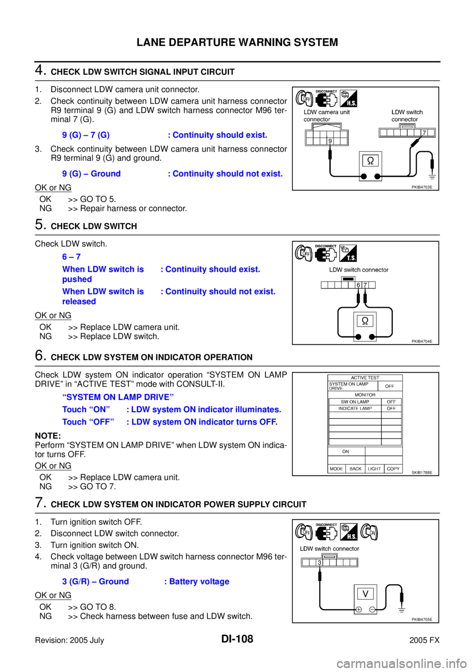
4. CHECK LDW SWITCH SIGNAL INPUT CIRCUIT
1. Disconnect LDW camera unit connector.
2. Check continuity between LDW camera unit harness connector R9 terminal 9 (G) and LDW switch harness connector M96 ter-
minal 7 (G).
3. Check continuity between LDW camera unit harness connector R9 terminal 9 (G) and ground.
OK or NG
OK >> GO TO 5.
NG >> Repair harness or connector.
5. CHECK LDW SWITCH
Check LDW switch.
OK or NG
OK >> Replace LDW camera unit.
NG >> Replace LDW switch.
6. CHECK LDW SYSTEM ON INDICATOR OPERATION
Check LDW system ON indicator operation “SYSTEM ON LAMP
DRIVE” in “ACTIVE TEST” mode with CONSULT-II.
NOTE:
Perform “SYSTEM ON LAMP DRIVE” when LDW system ON indica-
tor turns OFF.
OK or NG
OK >> Replace LDW camera unit.
NG >> GO TO 7.
7. CHECK LDW SYSTEM ON INDICATOR POWER SUPPLY CIRCUIT
1. Turn ignition switch OFF.
2. Disconnect LDW switch connector.
3. Turn ignition switch ON.
4. Check voltage between LDW switch harness connector M96 ter- minal 3 (G/R) and ground.
OK or NG
OK >> GO TO 8.
NG >> Check harness between fuse and LDW switch. 9 (G) – 7 (G) : Continuity should exist.
9 (G) – Ground : Continuity should not exist.
PKIB4703E
6 – 7
When LDW switch is
pushed : Continuity should exist.
When LDW switch is
released : Continuity should not exist.
PKIB4704E
“SYSTEM ON LAMP DRIVE”
Touch “ON” : LDW system ON indicator illuminates.
Touch “OFF” : LDW system ON indicator turns OFF.
SKIB1788E
3 (G/R) – Ground : Battery voltage
PKIB4705E
Page 1370 of 4731
LANE DEPARTURE WARNING SYSTEM DI-109
C
D E
F
G H
I
J
L
M A
B
DI
Revision: 2005 July 2005 FX
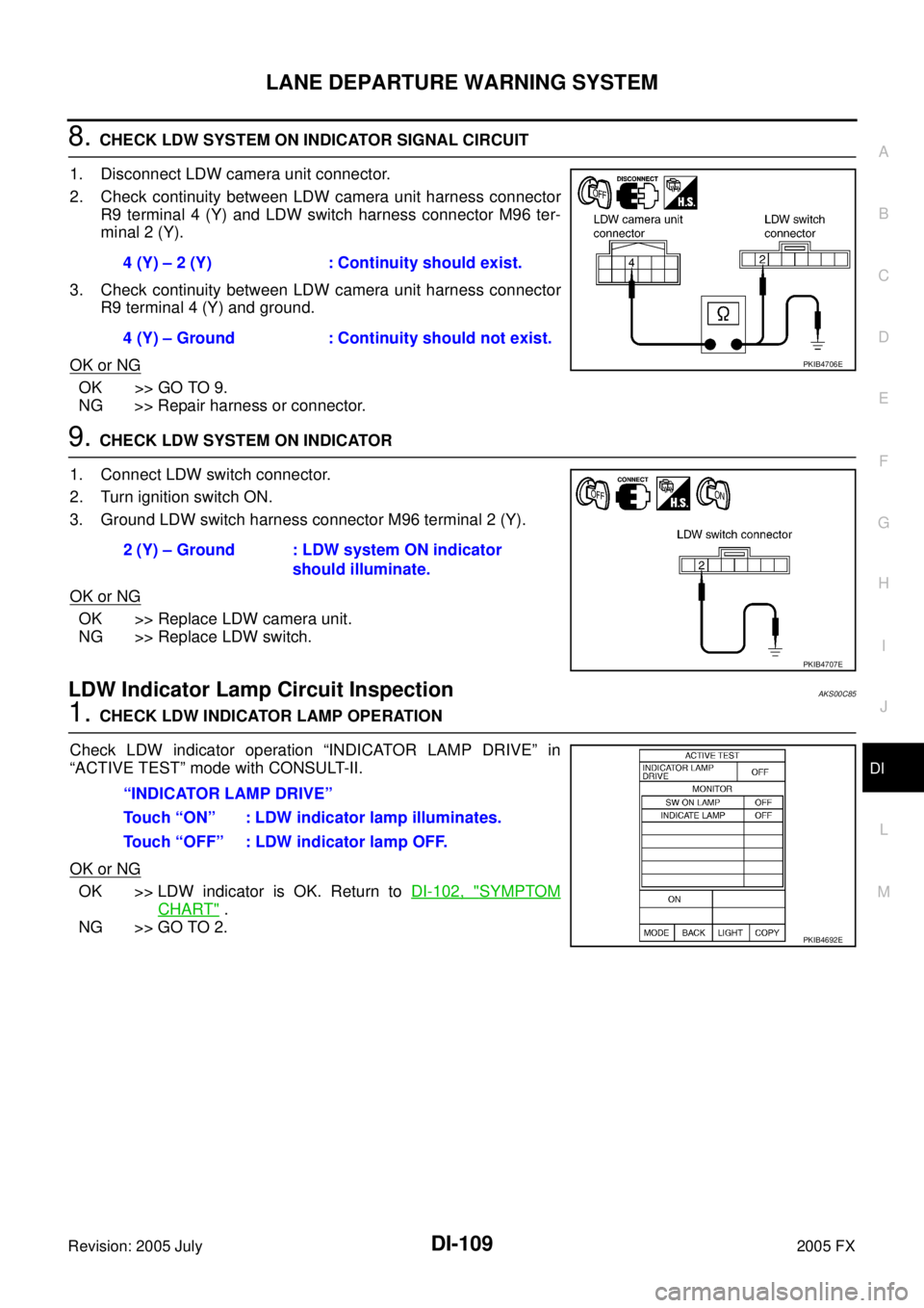
8. CHECK LDW SYSTEM ON INDICATOR SIGNAL CIRCUIT
1. Disconnect LDW camera unit connector.
2. Check continuity between LDW camera unit harness connector R9 terminal 4 (Y) and LDW switch harness connector M96 ter-
minal 2 (Y).
3. Check continuity between LDW camera unit harness connector R9 terminal 4 (Y) and ground.
OK or NG
OK >> GO TO 9.
NG >> Repair harness or connector.
9. CHECK LDW SYSTEM ON INDICATOR
1. Connect LDW switch connector.
2. Turn ignition switch ON.
3. Ground LDW switch harness connector M96 terminal 2 (Y).
OK or NG
OK >> Replace LDW camera unit.
NG >> Replace LDW switch.
LDW Indicator Lamp Circuit InspectionAKS00C85
1. CHECK LDW INDICATOR LAMP OPERATION
Check LDW indicator operation “INDICATOR LAMP DRIVE” in
“ACTIVE TEST” mode with CONSULT-II.
OK or NG
OK >> LDW indicator is OK. Return to DI-102, "SYMPTOM
CHART" .
NG >> GO TO 2. 4 (Y) – 2 (Y) : Continuity should exist.
4 (Y) – Ground : Continuity should not exist.
PKIB4706E
2 (Y) – Ground : LDW system ON indicator should illuminate.
PKIB4707E
“INDICATOR LAMP DRIVE”
Touch “ON” : LDW indicator lamp illuminates.
Touch “OFF” : LDW indicator lamp OFF.
PKIB4692E
Page 1371 of 4731
DI-110
LANE DEPARTURE WARNING SYSTEM
Revision: 2005 July 2005 FX
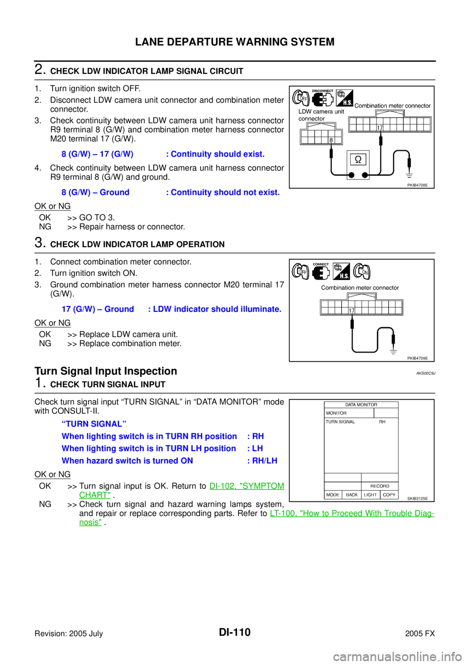
2. CHECK LDW INDICATOR LAMP SIGNAL CIRCUIT
1. Turn ignition switch OFF.
2. Disconnect LDW camera unit connector and combination meter connector.
3. Check continuity between LDW camera unit harness connector R9 terminal 8 (G/W) and combination meter harness connector
M20 terminal 17 (G/W).
4. Check continuity between LDW camera unit harness connector R9 terminal 8 (G/W) and ground.
OK or NG
OK >> GO TO 3.
NG >> Repair harness or connector.
3. CHECK LDW INDICATOR LAMP OPERATION
1. Connect combination meter connector.
2. Turn ignition switch ON.
3. Ground combination meter harness connector M20 terminal 17 (G/W).
OK or NG
OK >> Replace LDW camera unit.
NG >> Replace combination meter.
Turn Signal Input InspectionAKS00C9J
1. CHECK TURN SIGNAL INPUT
Check turn signal input “TURN SIGNAL” in “DATA MONITOR” mode
with CONSULT-II.
OK or NG
OK >> Turn signal input is OK. Return to DI-102, "SYMPTOM
CHART" .
NG >> Check turn signal and hazard warning lamps system, and repair or replace corresponding parts. Refer to LT- 1 0 0 , "
How to Proceed With Trouble Diag-
nosis" .
8 (G/W) – 17 (G/W) : Continuity should exist.
8 (G/W) – Ground : Continuity should not exist.
PKIB4708E
17 (G/W) – Ground : LDW indicator should illuminate.
PKIB4709E
“TURN SIGNAL”
When lighting switch is in TURN RH position : RH
When lighting switch is in TURN LH position : LH
When hazard switch is turned ON : RH/LH
SKIB3125E
Page 1387 of 4731
DI-126
REAR VIEW MONITOR
Revision: 2005 July 2005 FX
Rear View Is Not Displayed With The A/T Selector Lever In R-PositionAKS0068N
1. BACK-UP LAMP INSPECTION
1. Turn ignition switch ON.
2. Shift A/T selector lever to R position.
Does back-up lamp illuminate?
YES >> GO TO 2.
NO >> Check back-up lamp system. Refer to LT- 1 2 7 , "
BACK-UP LAMP" in LT section.
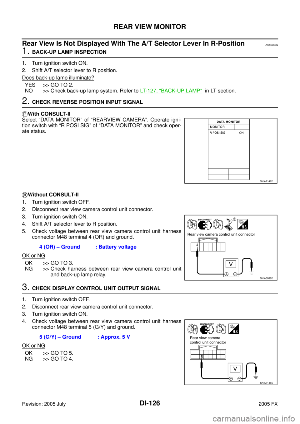
2. CHECK REVERSE POSITION INPUT SIGNAL
With CONSULT-II
Select “DATA MONITOR” of “REARVIEW CAMERA”. Operate igni-
tion switch with “R POSI SIG” of “DATA MONITOR” and check oper-
ate status.
Without CONSULT-II
1. Turn ignition switch OFF.
2. Disconnect rear view camera control unit connector.
3. Turn ignition switch ON.
4. Shift A/T selector lever to R position.
5. Check voltage between rear view camera control unit harness connector M48 terminal 4 (OR) and ground.
OK or NG
OK >> GO TO 3.
NG >> Check harness between rear view camera control unit and back-up lamp relay.
3. CHECK DISPLAY CONTROL UNIT OUTPUT SIGNAL
1. Turn ignition switch OFF.
2. Disconnect rear view camera control unit connector.
3. Turn ignition switch ON.
4. Check voltage between rear view camera control unit harness connector M48 terminal 5 (G/Y) and ground.
OK or NG
OK >> GO TO 5.
NG >> GO TO 4.
SKIA7147E
4 (OR) – Ground : Battery voltage
SKIA5086E
5 (G/Y) – Ground : Approx. 5 V
SKIA7148E
Page 1388 of 4731

REAR VIEW MONITOR DI-127
C
D E
F
G H
I
J
L
M A
B
DI
Revision: 2005 July 2005 FX
4. CHECK DISPLAY CONTROL UNIT CIRCUIT
1. Turn ignition switch OFF.
2. Disconnect display control unit connector.
3. Check continuity between rear view camera control unit harness connector M48 terminal 5 (G/Y) and display control unit harness
connector M75 terminal 8 (G/Y).
4. Check continuity between rear view camera control unit harness connector M48 terminal 5 (G/Y) and ground.
OK or NG
OK >> Replace display control unit.
NG >> Repair harness or connector.
5. CHECK CONTROL 1 SIGNAL
1. Turn ignition switch OFF.
2. Connect rear view camera control unit connector.
3. Shift A/T selector lever to R position.
4. Check voltage between rear view camera control unit harness connector M48 terminal 5 (G/Y) and ground.
OK or NG
OK >> GO TO 6.
NG >> Replace rear view camera control unit.
6. CHECK REAR VIEW CAMERA OPEN CIRCUIT
1. Turn ignition switch OFF.
2. Disconnect rear view camera connector.
3. Check continuity between rear view camera control unit harness connector M48 terminal 8 (R/W) and rear view camera harness
connector D108 terminal 1 (PU)
4. Check continuity between rear view camera control unit harness connector M48 terminal 9 and rear view camera harness con-
nector D108 terminal 4
5. Check continuity between rear view camera control unit harness connector M48 terminal 10 (G/W) and rear view camera harness
connector D108 terminal 3 (G)
OK or NG
OK >> GO TO 7.
NG >> Repair harness or connector. 5 (G/Y) – 8 (G/Y) : Continuity should exist.
5 (G/Y) – Ground : Continuity should not exist.
SKIA7149E
5 (G/Y) – Ground : Approx. 0 V
SKIA7150E
8 (R/W) – 1 (PU) : Continuity should exist.
9 – 4 : Continuity should exist.
10 (G/W) – 3 (G) : Continuity should exist.
SKIA5095E