Page 681 of 4731

AV-82
INTEGRATED DISPLAY SYSTEM
Revision: 2005 July 2005 FX
Ignition Signal InspectionAKS005UG
1. CHECK IGNITION SIGNAL
1. Turn ignition switch ON.
2. Check voltage between display unit harness connector M62 ter- minal 3 (G/R) and ground.
OK or NG
OK >> Replace display unit.
NG >> Check harness for open or short between display unit and fuse.
Audio Communication Line InspectionAKS005UH
1. CHECK HARNESS
1. Turn ignition switch OFF.
2. Disconnect audio unit connector and display unit connector.
3. Check continuity between audio unit and display unit.
4. Check continuity between display unit and ground.
OK or NG
OK >> GO TO 2.
NG >> Repair harness or connector.
2. CHECK AUDIO COMMUNICATION SIGNAL(DSP–AUD)
1. Connect display unit connector.
2. Turn ignition switch ON.
3. Check voltage between display unit harness connector M62 ter- minal 8 (LG) and ground.
OK or NG
OK >> GO TO 3.
NG >> Replace display unit. Battery voltage should exist.
SKIA9482E
Terminals
Continuity
Display unit Audio unit
Connector Terminal
(Wire color) Connector
Terminal
(Wire color)
M62 8 (LG)
M60 23 (LG)
Ye s
10 (B/Y) 21 (B/Y)
925
Terminals Continuity
Display unit
—
Connector Terminal (Wire color)
M62 8 (LG)
Ground No
10 (B/Y)
SKIA4994E
Approx. 3.5V or more
SKIA4396E
Page 682 of 4731
INTEGRATED DISPLAY SYSTEM AV-83
C
D E
F
G H
I
J
L
M A
B
AV
Revision: 2005 July 2005 FX
3. CHECK AUDIO COMMUNICATION SIGNAL(AUD–DSP)
1. Turn ignition switch OFF and connect audio unit connector.
2. Turn ignition switch ON.
3. Check voltage between audio unit harness connector M60 ter- minal 21 (B/Y) and ground.
OK or NG
OK >> GO TO 4.
NG >> Replace audio unit.
4. CHECK AUDIO COMMUNICATION SIGNAL(DSP–AUD)
1. Turn ignition switch ON.
2. Check the signal between display unit harness connector M62 terminal 8 (LG) and ground with CONSULT-ll or oscilloscope.
OK or NG
OK >> GO TO 5.
NG >> Replace display unit.
5. CHECK AUDIO COMMUNICATION SIGNAL(AUD–DSP)
1. Turn ignition switch ON.
2. Check the signal between display unit harness connector M62 terminal 10 (B/Y) and ground with CONSULT-ll or oscilloscope.
OK or NG
OK >> INSPECTION END
NG >> Replace audio unit. Approx. 3.5 V or more
SKIA4996E
8 (LG) - Ground:
SKIA4995ESKIA4402E
10 (B/Y) - Ground:
SKIA4999ESKIA4403E
Page 683 of 4731
AV-84
INTEGRATED DISPLAY SYSTEM
Revision: 2005 July 2005 FX
AV Communication Line InspectionAKS005UI
1. CHECK A/C AND AV SWITCH CIRCUIT
1. Turn ignition switch OFF.
2. Disconnect display unit connector and A/C and AV switch connector.
3. Check continuity between display unit and A/C and AV switch.
4. Check continuity between display unit and ground.
OK or NG
OK >> GO TO 2.
NG >> Repair harness or connector.
2. CHECK OF A/C AND AV SWITCH
Replace same normal A/C and AV switch and recheck the symptom.
Is the function normal?
YES >> Replace A/C and AV switch.
NO >> Replace display unit.
Terminals
Continuity
Display unit A/C and AV switch
Connector Terminal
(Wire color) Connector Te r m i n a l
(Wire color)
M62 11 (B/R)
M64 6 (B/R)
Ye s
13 (W/R) 8 (W/R)
12 7
SKIA5002E
Te r m i n a l s Continuity
Connector Terminal (Wire color) Terminal
M62 11 (B/R)
Ground No
13 (W/R)
SKIA7146E
Page 700 of 4731

NAVIGATION SYSTEM AV-101
C
D E
F
G H
I
J
L
M A
B
AV
Revision: 2005 July 2005 FX
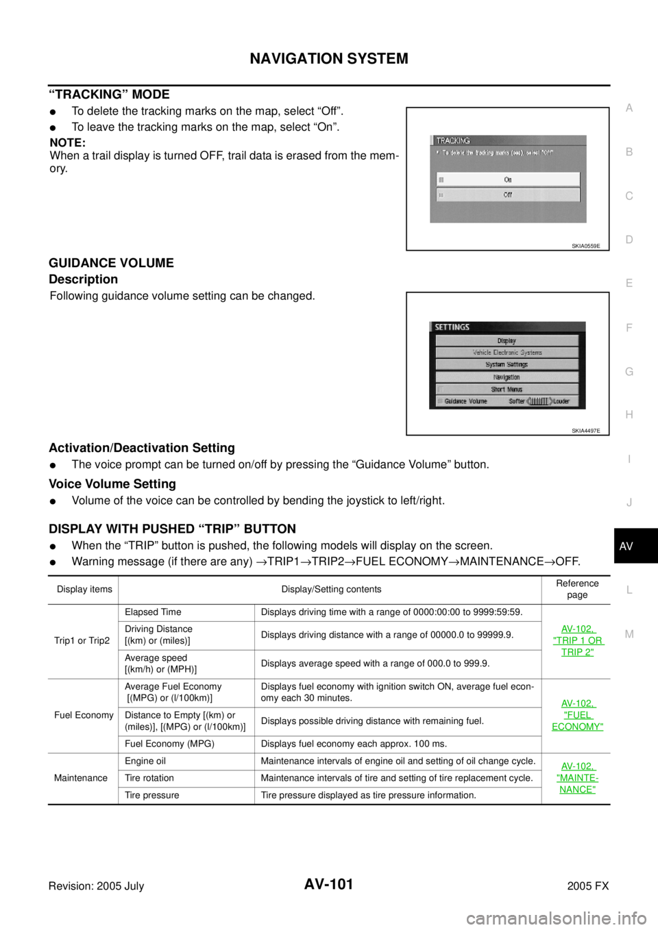
“TRACKING” MODE
�To delete the tracking marks on the map, select “Off”.
�To leave the tracking marks on the map, select “On”.
NOTE:
When a trail display is turned OFF, trail data is erased from the mem-
ory.
GUIDANCE VOLUME
Description
Following guidance volume setting can be changed.
Activation/Deactivation Setting
�The voice prompt can be turned on/off by pressing the “Guidance Volume” button.
Voice Volume Setting
�Volume of the voice can be controlled by bending the joystick to left/right.
DISPLAY WITH PUSHED “TRIP” BUTTON
�When the “TRIP” button is pushed, the following models will display on the screen.
�Warning message (if there are any) →TRIP1 →TRIP2 →FUEL ECONOMY →MAINTENANCE →OFF.
SKIA0559E
SKIA4497E
Display items Display/Setting contents Reference
page
Trip 1 o r Trip2 Elapsed Time Displays driving time with a range of 0000:00:00 to 9999:59:59.
AV-102,
"TRIP 1 OR
TRIP 2"
Driving Distance
[(km) or (miles)] Displays driving distance with a range of 00000.0 to 99999.9.
Average speed
[(km/h) or (MPH)] Displays average speed with a range of 000.0 to 999.9.
Fuel Economy Average Fuel Economy
[(MPG) or (l/100km)] Displays fuel economy with ignition switch ON, average fuel econ-
omy each 30 minutes. AV-102,
"FUEL
ECONOMY"
Distance to Empty [(km) or
(miles)], [(MPG) or (l/100km)] Displays possible driving distance with remaining fuel.
Fuel Economy (MPG) Displays fuel economy each approx. 100 ms.
Maintenance Engine oil Maintenance intervals of engine oil and setting of oil change cycle.
AV-102,
"MAINTE-
NANCE"
Tire rotation Maintenance intervals of tire and setting of tire replacement cycle.
Tire pressure Tire pressure displayed as tire pressure information.
Page 718 of 4731

NAVIGATION SYSTEM AV-119
C
D E
F
G H
I
J
L
M A
B
AV
Revision: 2005 July 2005 FX
Terminals and Reference Value for NAVI Control UnitAKS007IV
Terminal No.
(Wire color) Item Signal
input/
output Condition
Voltag e Example of
symptom
+– Ignition
switch Operation
1 (B) Ground Ground — ON — Approx. 0 V —
2 (Y) Ground Battery power
supply Input OFF — Battery voltage System does not
work properly.
3 (Y)
4 (B) Ground Ground — ON — Approx. 0 V —
6 (LG) Ground ACC power
supply Input ACC — Battery voltage System does not
work properly.
7 (LG) 8 (PU) Voice guide sig-
nal Output ON Press the “GUIDE/
VOICE” button. Only route guide
and operation
guide are not
heard.
9 — Shield ground — — — — —
14 — Shield ground — — — — —
15 (B) 17 RGB signal
(B: blue) Output ON Select “Display
Diagnosis (NAVI)” of
CONFIRMATION/
ADJUSTMENT
function. RGB screen
looks yellowish.
16 (G) 14 RGB synchro-
nizing signal Output ON
Press the “MAP”
button. RGB screen is
rolling.
17 — Shield ground — — — — —
18 (R) 17 RGB signal
(R: red) Output ON Select “Display
Diagnosis (NAVI)” of
CONFIRMATION/
ADJUSTMENT
function. RGB screen
looks bluish.
21 (W) 17 RGB signal
(G: green) Output ON Select “Display
Diagnosis (NAVI)” of
CONFIRMATION/
ADJUSTMENT
function. RGB screen
looks reddish.
25 (R) Ground Illumination sig-
nal Input OFF Lighting switch posi-
tion 1st or 2nd Approx. 12 V
Night illumina-
tion for switches
does not illumi-
nate.
Lighting switch posi-
tion OFF Approx. 0 V
SKIA0171J
SKIA4979E
SKIA0164E
SKIA4977E
SKIA4978E
Page 719 of 4731

AV-120
NAVIGATION SYSTEM
Revision: 2005 July 2005 FX
26 (G) Ground Ignition signal Input ON — Battery voltage System does not
work properly.
27 (OR) Ground Reverse signal Input ON Selector lever in R
position Approx. 12 VThe navigation
current-location
mark moves
strangely when
the vehicle is
moving back-
wards.
Selector lever not in
R position Approx. 0 V
28 (GY) Ground Vehicle speed
signal (8-pulse) Input ON When vehicle speed
is approx. 40 km/h
(25 MPH) Navigation cur-
rent-location
mark does not
indicate the cor-
rect position.
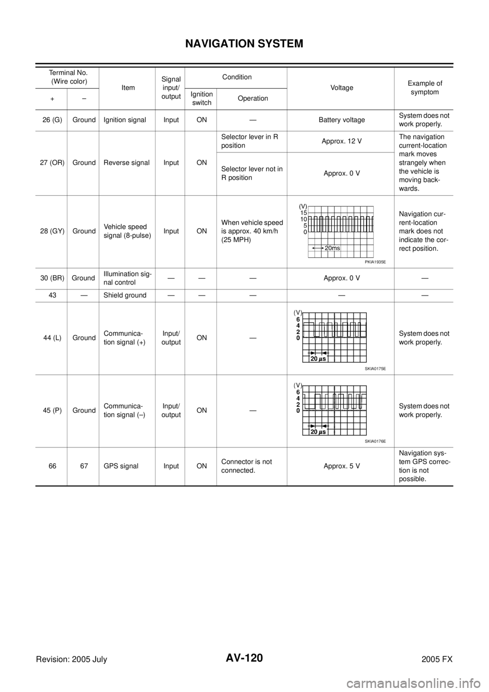
30 (BR) Ground Illumination sig-
nal control — — — Approx. 0 V —
43 — Shield ground — — — — —
44 (L) Ground Communica-
tion signal (+) Input/
output ON —
System does not
work properly.
45 (P) Ground Communica-
tion signal (–) Input/
output ON — System does not
work properly.
66 67 GPS signal Input ON Connector is not
connected. Approx. 5 V Navigation sys-
tem GPS correc-
tion is not
possible.
Te r m i n a l N o .
(Wire color) Item Signal
input/
output Condition
Voltage Example of
symptom
+– Ignition
switch Operation
PKIA1935E
SKIA0175E
SKIA0176E
Page 720 of 4731

NAVIGATION SYSTEM AV-121
C
D E
F
G H
I
J
L
M A
B
AV
Revision: 2005 July 2005 FX
Terminals and Reference Value for Display Control UnitAKS007IW
Terminal No.
(Wire color) Item Signal
input/
output Condition
Voltage Example of
symptom
+– Ignition
switch Operation
1 (W/L) Ground Battery Power
supply Input OFF — Battery voltage System does not
work properly.
2 (W/G) Ground Power Sup-
ply (Inverter) Output ON — Approx. 9 V Screen is not
shown.
3 (B) Ground Ground — ON — Approx. 0 V —
4 (BR/W) Ground Power Sup-
ply (Signal) Output ON — Approx. 9 V
Screen is not
shown.
5 (P) Ground (Inverter)
Ground — ON — Approx. 0 V —
6 (OR) Ground Reverse
signal Input ON Selector lever in R
position Approx. 12 V
Impossible to
gain direction of
vehicle.
Selector lever not
in R position Approx. 0 V
7 (P/L) Ground (Signal)
Ground — ON — Approx. 0 V —
10 (LG/R) Ground ACC power
supply Input ACC — Battery voltage System does not
work properly.
12 (G/R) Ground Ignition signal Input ON — Battery voltage A/C operation is
not possible.
Vehicle informa-
tion setting is not
possible.
13 (B) Ground Sysco — ON — Approx. 0 V —
14 (R/L) Ground Illumination
signal Input OFF Lighting switch
position 1st or 2nd Approx. 12 V Audio unit illumi-
nation does not
come on when
lighting switch is
ON (position 1).
Lighting switch
position OFF Approx. 0 V
16 (R/G) Ground Vehicle speed
signal (8–
pulse) Input ON When vehicle
speed is approx.
40 km/h (25 MPH) Value of vehicle
information is
not accurately
displayed.
25 (L) — CAN H — — — — —
26 (R) — CAN L — — — — —
28 (B/R) Ground Communica-
tion signal (+) Input/
Output ON —
System does not
work properly.
29 — Shield ground — — — — —
PKIA1935E
SKIA0175E
Page 721 of 4731

AV-122
NAVIGATION SYSTEM
Revision: 2005 July 2005 FX
30 (W/R) Ground Communica-
tion signal (–) Input/
output ON — System does not
work properly.
32 (BR) Ground Communica-
tion signal (+) Input/
output ON — System does not
work properly.
33 — Shield ground — — — — —
34 (Y) Ground Communica-
tion signal (–) Input/
output ON — System does not
work properly.
36 (PU) Ground Display Com-
munication
signal
(DCU-DSP) Output ON
Press the “TRIP”
button. Though a screen
is displayed, it is
impossible to
adjust bright-
ness.
37 — Shield ground — — — — —
38 (LG) Ground Display Com-
munication
signal
(DSP-DCU) Input ON
Press the “TRIP”
button. Though a screen
is displayed, it is
impossible to
adjust bright-
ness.
39 — Shield ground — — — — —
40 (LG) Ground Audio
Communica-
tion signal Output ON
Operate audio
volume. Audio dose not
operate properly.
41 — Shield ground — — — — — Terminal No.
(Wire color) Item Signal
input/
output Condition
Voltag e Example of
symptom
+– Ignition
switch Operation
SKIA0176E
SKIA0175E
SKIA0176E
SKIA4364E
SKIA4363E
SKIA4403E